Table of Contents
Advertisement
Quick Links
Advertisement
Table of Contents

Related Manuals for DP dp-control III

Summary of Contents for DP dp-control III
- Page 1 Installation/Operating Manual dp-control III(+)
- Page 2 2 / 76 Legal information/Copyright Original operating manual dp-control III(+) All rights reserved. The contents provided herein must neither be distributed, copied, reproduced, edited or processed for any other purpose, nor otherwise transmitted, published or made available to a third party without the manufacturer's express written consent.
-
Page 3: Table Of Contents
Contents General....................... 6 Principles ............................. 6 Target group ............................ 6 Other applicable documents ........................ 6 Symbols ............................... 6 Key to safety symbols/markings ...................... 7 Safety ......................... 8 General .............................. 8 Intended use ............................ 8 Personnel qualification and training ..................... 8 Consequences and risks caused by non-compliance with this operating manual ....... 8 Safety awareness .......................... - Page 4 6.2.1 Operating status of the system.................... 25 6.2.2 Bluetooth connection...................... 25 6.2.3 Locking/unlocking the screen .................... 26 6.2.4 Operating status of the pump .................... 26 6.2.5 Information on the system ..................... 26 Operating the device via the control panel .................. 27 6.3.1 Unlocking the screen......................
- Page 5 8.9.3 Tank filling .......................... 37 8.9.4 Drinking water protection....................... 37 8.9.5 Rainwater filling ........................ 37 8.10 Special operating modes ........................ 37 8.10.1 Jockey pump system...................... 37 8.11 Field bus ............................ 38 Servicing/Inspection.................. 39 Safety regulations .......................... 39 Servicing/Inspection........................... 39 9.2.1 Supervision of operation...................... 39 9.2.2 Handling messages.......................
-
Page 6: General
The serial number uniquely describes the product and is used as identification in all further business processes. In the event of damage, immediately contact your nearest DP service facility to maintain the right to claim under warranty. 1.2 Target group This operating manual is aimed at the target group of trained and qualified specialist technical personnel. -
Page 7: Key To Safety Symbols/Markings
1.5 Key to safety symbols/markings Table 3: Definition of safety symbols/markings Symbol Description DANGER DANGER This signal word indicates a high-risk hazard which, if not avoided, will result in death or serious injury. WARNING WARNING This signal word indicates a medium-risk hazard which, if not avoided, could result in death or serious injury. -
Page 8: Safety
2 Safety All the information contained in this section refers to hazardous situations. DANGER In addition to the present general safety information the action-related safety information given in the other sections must be observed. 2.1 General – This operating manual contains general installation, operating and maintenance instructions that must be observed to ensure safe operation of the system and prevent personal injury and damage to property. -
Page 9: Safety Awareness
9 / 76 The software has been specially created for this product and thoroughly tested. Making changes or additions to the software or parts of the software is prohibited. This does not, however, apply to software updates supplied by DP. -
Page 10: Transport/Storage/Disposal
1. On transfer of goods, check each packaging unit for damage. 2. In the event of in-transit damage, assess the exact damage, document it and notify DP or the supplying dealer and the insurer about the damage in writing immediately. - Page 11 The product is classified as special waste due to several installed components: 1. Dismantle the product. 2. Separate and sort the materials, e.g. by: - Aluminium - Plastic cover (recyclable plastic) 3. Dispose of materials in accordance with local regulations or in another controlled manner.
-
Page 12: Description
Fixed speed Speed-controlled by cabinet-mounted frequency inverter Speed-controlled by motor-mounted frequency inverter Number of pumps that can be connected 4.4 Name plate dp-control III+ F: 4p (6p) VC/SVP:6p www.dp-pumps.com P / N: SPBB10079122 24VAC - 50/60 Hz - 20W IP20/IP55... -
Page 13: Technical Data
– Modbus RTU– RS485 – Profibus DP (optional) – Bacnet MSTP (optional) Bus communication is possible with frequency inverters of the following manufacturers: – DP Var+ / DP Var – Danfoss Microdrive FC 51 – Danfoss Aquadrive FC 202 – Danfoss Mididrive FC280 4.6 Technical data... - Page 14 Characteristic Value dp-control III+ Storage temperature -10 °C to +70 °C ✘ ✘ Relative humidity 5 % to 90 %, non-condensing ✘ ✘ Maximum height above sea level 2000 m ✘ ✘ Type of protection / enclosure Display LCD segment display ✘ ✘ Button Turn/push button ✘...
-
Page 15: Combination Options
Not every frequency inverter can be used for every operating mode. Internal bus communication forms the basis for this purpose. The following combinations of frequency inverter and operating mode are recommended by DP : Table 7: Combinations of frequency inverters and operating modes Operating mode... -
Page 16: Dimensions And Weight
4.9 Dimensions and weight 175.3 155.3 Fig. 2: Dimensions Table 8: Weight Design Gewicht [kg] dp-control III 0,50 16 / 76 dp-control III+ 0,62... -
Page 17: Installation At Site
5 Installation at Site 5.1 Safety regulations DANGER Incorrect installation Danger to life! Ø Install the control unit in a flood-proof location. Ø Never use the control unit in potentially explosive atmospheres. 5.2 Checking ambient conditions 1. Check and safeguard ambient conditions. 2. -
Page 18: Electrical Connection
Fig. 5: Position of mounting pads 3. Fit the four mounting pads in the grooves above (2x) and to the left (1x) and right (1x) of the control unit. 4. Tighten the grub screws on the mounting pads (from the rear) with a 2.5 mm Allen key to a torque of 0.2 Nm max. -
Page 19: Electrical Connections
5.4.1 Electrical connections Fig. 6: Terminal strip, mainboard Table 9: Mainboard connections Code Designation Description Potential equalisation 24 V AC power supply 19 / 76 RS485_1 communication cable. A terminating resistor located next to this connection has to be set to ON if it is the end of the communication cable. R1_NO Switching relay Alert. - Page 20 Code Designation Description DO1_NO Digital outputs 1 to 4. Pre-configured for starting up pumps 1 to 4. DO2_C DO2_NO DO3_C DO3_NO DO4_C DO4_NC Connections for leakage detection Digital inputs 1 to 12, configuration depending on system requirements DI10 DI11 DI12 +24V +24 V connections for digital inputs 1 to 12 +24V...
- Page 21 Fig. 7: Terminal strips on extension board Table 10: Connections of the extension board Code Designation Description DO5_C Digital outputs 5 to 12 with configurable function DO5_NO 21 / 76 DO6_C DO6_NO DO7_C DO7_NO DO8_C DO8_NC DO9_C DO9_NO DO10_C DO10_NO DO11_C DO11_NO...
-
Page 22: Connecting To Power Supply
1. Connect the control unit to a power supply system suitable for its technical data. 5.4.3 Using a motor contactor (for F systems only) DP recommends using motor contactors for switching the pump sets on and off. The motor contactors used have to correspond with the pump set input power. -
Page 23: Operation
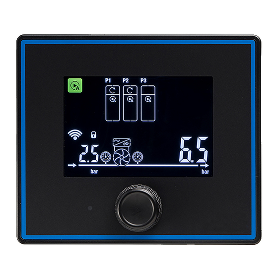
6 Operation 6.1 Control panel Fig. 8: Control panel Screen [ð Section 6.1.1, Page 23] Turn/push button [ð Section 6.1.2, Page 23] Status LED [ð Section 6.1.3, Page 23] 6.1.1 Screen To save power the screen is turned off automatically. To turn on the screen push or turn the turn/push button arranged below the screen. If a message is active, the screen also lights up and displays the current message ID as well as the system status. -
Page 24: Symbols On The Screen
Table 11: Explanation of the status LED Colour of the status LED Description Green (flashing) System in operation, no messages are active. Green (continuous) One or more information messages are active. Yellow (continuous) One or more warning messages are active (as well as any messages of a lower priority). -
Page 25: Operating Status Of The System
6.2.1 Operating status of the system Table 12: Symbols for the operating status of the system Symbol Description Status OK No warning messages or alert messages are active. Information messages may be present. The system is running without any problems. Warning One or more warning messages are active (as well as any messages of a lower priority). -
Page 26: Locking/Unlocking The Screen
6.2.3 Locking/unlocking the screen Table 14: Symbols for locking/unlocking the screen Symbol Description Screen settings locked No settings can be made but information can still be displayed, e.g. pump load. Error messages are limited to the selected part. Screen settings unlocked Changes can be made on the screen. -
Page 27: Operating The Device Via The Control Panel
Table 16: Symbols for information on the system Position Refers to Description Display for suction-side Depending on the connected sensors the following values are displayed: sensors – Version with pressure gauge: Displays the pressure at the inlet of the pressure booster system. –... -
Page 28: Unlocking The Screen
6.3.1 Unlocking the screen When the screen is locked, no settings can be made. In this state, only information can be displayed. 1. Turn the turn/push button to select the Locking/unlocking the screen symbol. Then press the turn/push button. ð The symbol flashes. 2. -
Page 29: Activating The Bluetooth Connection
ð The firmware version is displayed on the bottom left and bottom right. 6.4 Operation via the app Further configurations can only be made via the DP-Control app. The app is available in the App Store or Google Play. 29 / 76... -
Page 30: Commissioning/Start-Up/Shutdown
7 Commissioning/Start-up/Shutdown 7.1 Ambient conditions for commissioning and operation Table 17: Ambient conditions for operation Condition Value Ambient temperature 0 ... 60 °C Relative humidity Min. 5 % to max. 90 % Non-condensing Installation altitude Max. 2000 m above MSL (higher installation altitudes are subject to a reduction factor) 7.2 Commissioning A checklist can be used for commissioning. -
Page 31: Basic Configurations Of The Pressure Booster System
8 Basic configurations of the pressure booster system The control unit controls several pump sets according to the configured setpoint and bandwidth. Pump sets are started up and stopped when the current discharge pressure is not within the bandwidth arranged symmetrically below and above the setpoint. When none of the pump sets of the pressure booster system are running, the first pump set is started up immediately as soon as the current discharge pressure sinks below the setpoint minus half the bandwidth. -
Page 32: Svp System
The Operating Mode (parameter 1-1-2-3) has to be set to Operation on frequency inverter and the Frequency Control Type (parameter 1-1-2-5) has to be set to Single-pump operation . Pump Groups (parameter 1-1-2-6) has to be set to Pump-group control. The Frequency Inverter Type (parameter 1-1-2-4) has to be selected. -
Page 33: Pump Operating Mode
8.4.5 Pump operating mode Pump operating The operating mode (manual-0-automatic) can be selected on the screen or via an external mode switch. The source has to be configured (parameter 1-1-5-1). The pump operating mode for each pump set can then be separately set to "Manual-ON", "Manual-OFF" and "Automatic". Mains-operated pump sets that have been started manually run at full nominal speed;... -
Page 34: Functional Check Run
8.5.4 Functional check run Functional check run A Check Run can be activated for the pump set (parameter 2-4-4-1), so the pump set starts up regularly if it has not been operated for a defined period of time. The Function can be triggered by different sources (parameter 2-4-4-2). -
Page 35: Discharge Pressure Monitoring
operated on frequency inverters (parameter 2-4-1-4). The Options are Stop all pumps, Freeze number of pumps running and speed or Run a specific number of pump sets at fixed speed (parameter 2-4-1-6). 8.6.3 Discharge pressure monitoring Discharge pressure The current discharge pressure is monitored continuously. When the pressure falls below monitoring the configured Maximum Discharge Pressure (parameter 2-5-5-1-1) or exceeds the configured Minimum Discharge Pressure (parameter 2-5-5-2-1), a message is output after a... -
Page 36: Hygiene Functions And Special Functions
8.7 Hygiene functions and special functions 8.7.1 Temperature monitoring Temperature When Temperature Monitoring is Enabled (parameter 2-5-3-2-1), the temperature is monitoring measured by a thermometer. The temperature measurement input has to be configured for this purpose (parameter 1-3-5). The Response to the temperature exceeding the Maximum Temperature (parameter 2-5-3-2-2) or falling below the Minimum Temperature (parameter 2-5-3-2-3) can be selected as only a Message or, in addition, Flushing of the pressure booster system (parameter 2-5-3-2-4). -
Page 37: Tank Filling
Critical Water Level (parameter 2-7-1-2-10) can be set. With High-water Level (parameter 2-7-1-2-16) and Level for Reset High-water Level (parameter 2-7-1-2-15) a warning for a possible tank overflow can be set. 8.9.3 Tank filling Tank filling Tank filling is controlled by the two fill levels Start Tank Filling Level (parameter 2-7-1-2-11) and Stop Tank Filling Level (parameter 2-7-1-2-14). -
Page 38: Field Bus
be set to Mains operation. Pump Groups (parameter 1-1-2-6) has to be set to Pump-group and jockey-pump control . For switching between jockey pump and base load pump group Over-/Undersupply (parameter 2-4-3-1) can be selected and the Time of Over-/Undersupply (parameter 2-4-3-2) can be set. -
Page 39: Servicing/Inspection
Ø Prevent the device from being re-started unintentionally when carrying out any maintenance and installation work. NOTE All maintenance work, service work and installation work can be carried out by DP Service or authorised workshops. 9.2 Servicing/Inspection 9.2.1 Supervision of operation – Ensure sufficient cooling of the control unit. -
Page 40: Parameter Lists
Operation on frequency inverter Frequency driven Everybody Service Mains operation 1-1-2-4 Frequency inverter type KSB PumpDrive2 (Eco) PumpDrive2 Everybody Service DP Var(+) Danfoss MicroDrive Danfoss MidiDrive Danfoss AquaDrive 1-1-2-5 Frequency control type Multi-pump operation Multi-pump operation Everybody Service Single-pump operation 1-1-2-6... - Page 41 Parameter Description Value range and dependencies Factory setting Access level Read Access level Write Re-start required 1-1-3-2 Number of base load pumps 1 … (number of pumps - number of peak- Number of pumps Everybody Nobody load pumps) if pump groups = base-load and peak-load pump control 1 …...
-
Page 42: Pump Settings
10.1.2 Pump settings Table 19: Pump settings parameters Parameter Description Value range and dependencies Factory setting Access level Read Access level Write Re-start required Pumps Everybody Nobody 1-2-1 Base load pump Everybody Nobody 1-2-1-1 Pump data Everybody Nobody 1-2-1-1-5 Head 0 Pump data Everybody Service... - Page 43 Parameter Description Value range and dependencies Factory setting Access level Read Access level Write Re-start required 1-2-1-1-32 NPSH 6 Pump data Everybody Service 1-2-1-1-33 Optimal flow rate Pump data Everybody Service 1-2-1-1-34 Low-flow limit rate percentage Pump data Everybody Service 1-2-1-2 Motor drive data Everybody Nobody...
- Page 44 Parameter Description Value range and dependencies Factory setting Access level Read Access level Write Re-start required 1-2-1-2-22 Function input 1 [1] Reset Motor data Everybody Service [10] Reversing 1-2-1-2-23 Function input 2 [0] No operation Motor data Everybody Service [1] Reset [2] Coast inverse 1-2-1-2-24 Function input 3...
- Page 45 Parameter Description Value range and dependencies Factory setting Access level Read Access level Write Re-start required 1-2-1-2-29 Control timeout function [4] Max. speed Motor data Everybody Service [5] Stop and trip 1-2-1-2-30 Coasting select [0] Digital input Motor data Everybody Service [1] Bus [2] Digital input and bus...
-
Page 46: Input / Outputs
10.1.3 Input / outputs Table 20: Input/output parameters Parameter Description Value range and dependencies Factory setting Access level Read Access level Write Re-start required Inputs/outputs Everybody Nobody 1-3-1 Analog inputs Everybody Nobody Note: To change a function, the Everybody Nobody function first has to be removed by changing it to 'No function'. - Page 47 Parameter Description Value range and dependencies Factory setting Access level Read Access level Write Re-start required 1-3-3-1 Input 1 None None Everybody Service 1-3-3-2 Input 2 Pressure switch 1-3-3-3 Input 3 Float switch 1-3-3-4 Input 4 Flow switch 1-3-3-5 Input 5 Failure motor-circuit breaker pump 1 1-3-3-6 Input 6...
- Page 48 Parameter Description Value range and dependencies Factory setting Access level Read Access level Write Re-start required 1-3-3-1 Input 1 Manual-mode at M-0-A-switch rainwater None Everybody Service pump 2 1-3-3-2 Input 2 Automatic-mode at M-0-A-switch rainwater 1-3-3-3 Input 3 pump 1 1-3-3-4 Input 4 Automatic-mode at M-0-A-switch rainwater...
- Page 49 Parameter Description Value range and dependencies Factory setting Access level Read Access level Write Re-start required 1-3-4-1 Output 1 No function None Everybody Service 1-3-4-2 Output 2 Start/stop pump 1 1-3-4-3 Output 3 Start/stop pump 2 1-3-4-5 Output 5 (extension board) Start/stop pump 3 1-3-4-6 Output 6 (extension board)
- Page 50 Parameter Description Value range and dependencies Factory setting Access level Read Access level Write Re-start required 1-3-5-3 Selection of thermometer function Ambient temperature Ambient temperature Everybody Service Water temperature 1-3-7 Calibration 1-3-7-1 Sensors 1-3-7-1-1 Pressure sensor on suction side 1-3-7-1-1-1 Value at 4 mA 0 …...
-
Page 51: Further Configuration Settings
10.1.4 Further configuration settings Table 21: Further configuration settings parameters Parameter Description Value range and dependencies Factory setting Access level Read Access level Write Re-start required Field bus Everybody Nobody 1-4-1 Modbus RTU Disabled Disabled Everybody Service Enabled 1-4-2 Slave address 1 …... -
Page 52: Settings
Parameter Description Value range and dependencies Factory setting Access level Read Access level Write Re-start required 1-7-1-3 Seconds 0 … 59 Everybody Service 1-7-2 Date Everybody Nobody 1-7-2-1 Year 2019 … 2099 Everybody Service 1-7-2-2 Month 1 … 12 Everybody Service 1-7-2-3 1 …... -
Page 53: Pump Operating Mode
Parameter Description Value range and dependencies Factory setting Access level Read Access level Write Re-start required 2-1-3 Alternative setpoint 0 … 99 bar 2.5 bar Everybody Customer 2-1-4 Alternative setpoint selection Disabled Disabled Everybody Customer Time enabled Digital input enabled 2-1-5 Alternative set-point start time 0 … 24 h Everybody... -
Page 54: Timers
Parameter Description Value range and dependencies Factory setting Access level Read Access level Write Re-start required 2-2-1-4 Pump 4 Manual-On Manual-Off Everybody Display/Customer 2-2-1-5 Pump 5 Automatic Manual-Off Everybody Display/Customer Manual-Off Manual-On 2-2-1-6 Pump 6 Automatic Manual-Off Everybody Display/Customer Manual-Off Manual-On 2-2-2 Rainwater operating mode... -
Page 55: Pump Protection
10.2.4 Pump protection Table 25: Pump protection parameters Parameter Description Value range and dependencies Factory setting Access level Read Access level Write Re-start required Pump protection Everybody Nobody 2-4-1 General 2-4-1-1 Minimum frequency 0 … maximum frequency 60 Hz Everybody Service 2-4-1-2 Maximum frequency Minimum frequency …... - Page 56 Parameter Description Value range and dependencies Factory setting Access level Read Access level Write Re-start required 2-4-2-6 Ramp down time 0 … 60 s Everybody Service 2-4-3 Changeover from jockey pump to Everybody Service base load pumps 2-4-3-1 Over-/undersupply Oversupply Oversupply Everybody Service Undersupply...
-
Page 57: System Protection
Parameter Description Value range and dependencies Factory setting Access level Read Access level Write Re-start required 2-4-8-1 Trigger active high/low Active low 1: Active low Everybody Service 2-4-8-2 Trigger delay 0 … 99 s 1 s Everybody Service 10.2.5 System protection Table 26: System protection parameters Parameter Description Value range and dependencies... - Page 58 Parameter Description Value range and dependencies Factory setting Access level Read Access level Write Re-start required 2-5-1-3-2 Minimum suction-side pressure for Minimum suction-side pressure for stop … 1.5 bar Everybody Service reset Maximum pressure sensor range 2-5-1-6 Flow switch 2-5-1-6-2 Discharge pressure deviation 0 …10 bar 1 bar...
- Page 59 Parameter Description Value range and dependencies Factory setting Access level Read Access level Write Re-start required 2-5-3-3-2 Source Flow estimation (VFD) Everybody Service 2-5-3-3-3 Time of stagnation 0 … 7 d 24 h Everybody Service 2-5-3-3-4 Response Message Message Everybody Service Flushing with check run 2-5-3-4 Forced flushing...
-
Page 60: Accumulator
Parameter Description Value range and dependencies Factory setting Access level Read Access level Write Re-start required 2-5-6-3 Ramp-step for increasing set-point 0 …10 bar 0.1 bar Everybody Service 2-5-6-4 Maximum time on ramp-step 0 … 600 s 60 s Everybody Service 2-5-6-5 Maximum number of attempts 1 …... - Page 61 Parameter Description Value range and dependencies Factory setting Access level Read Access level Write Re-start required 2-7-1-1-1 Drinking water filling Disabled Disabled Everybody Service Enabled 2-7-1-2 Tank level 2-7-1-2-4 Absolute height at 0 % 0 … absolute height at 100 % Position of sensor Everybody Service...
- Page 62 Parameter Description Value range and dependencies Factory setting Access level Read Access level Write Re-start required 2-7-1-5-2 Maximum time between usage of 0… 31 d 168 h Everybody Service drinking water 2-7-1-5-3 Response Message only 0: Message only Everybody Service Message and flushing of inlet line 2-7-1-5-4 Time for flushing drinking water 0 …...
-
Page 63: Control Algorithms
10.2.8 Control algorithms Table 29: Control algorithms parameters Parameter Description Value range and dependencies Factory setting Access level Read Access level Write Re-start required Control algorithms Service Nobody 2-8-1 PID controller 2-8-1-1 Proportional constant Value range according to controller Service Service 2-8-1-2 Integral constant Value range according to controller... -
Page 64: Modbus
10.3 Modbus Modbus register Description Value range Type Decimal Read/write 47001 Reset all current messages 1: Reset all uint16 47002 Setpoint 0 … 99 bar uint16 47003 Alternative setpoint 0 … 99 bar uint16 47004 Hours 0 … 23 uint16 47005 Minutes 0 …... - Page 65 Modbus register Description Value range Type Decimal Read/write 47046 Pump load P5 uint16 47047 Pump load P6 uint16 47048 Operating mode, pump 1 0:AUTOMATIC uint16 1:OFF 2:MANUAL 47049 Operating mode, pump 2 0:AUTOMATIC uint16 1:OFF 2:MANUAL 47050 Operating mode, pump 3 0:AUTOMATIC uint16 1:OFF...
- Page 66 Modbus register Description Value range Type Decimal Read/write 47059 Status, pump 6 0: IDLE uint16 1: STARTING 2: RUNNING 3: STOPPING 47060 Frequency, pump 1 uint16 47061 Frequency, pump 2 uint16 47062 Frequency, pump 3 uint16 47063 Frequency, pump 4 uint16 47064 Frequency, pump 5...
-
Page 67: Messages
11 Messages The following tables contain an overview of messages displayed by the control unit in alternation with the current system status in the bottom right corner of the screen. Some messages have to be reset manually. [ð Section 9.2.2, Page 39] 11.1 Messages for specific pumps In the range from 100 to 699 the first digit stands for the pump number. - Page 68 Paramete Description Status Reset mode messag (factory setting) 2-9-4-13 AMA fault frequency inverter pump 2 Alert Manual 2-9-4-14 Short circuit frequency inverter pump 2 Alert Manual 2-9-4-15 Safety stop frequency inverter pump 2 Alert Manual 2-9-4-16 Configuration invalid frequency inverter pump 2 Alert Manual 2-9-5-1...
-
Page 69: Messages For Additional Devices
Paramete Description Status Reset mode messag (factory setting) 2-9-10-3 Communication error frequency inverter pump 5 Alert Auto 2-9-10-4 Incorrect check sum frequency inverter pump 5 Alert Auto 2-9-10-5 Internal fault frequency inverter pump 5 Alert Auto 2-9-10-6 Mains fault frequency inverter pump 5 Alert Manual 2-9-10-7... -
Page 70: Messages For Specific Functions
Paramete Description Status Reset mode messag (factory setting) 2-9-14-5 Broken wire pressure sensor discharge side Alert Manual 2-9-14-6 Discharge-side pressure too low too often Information Auto 2-9-14-7 Discharge-side pressure too high too often Information Auto 2-9-15-1 Fault pressure sensor at tank Alert Manual 2-9-15-2... - Page 71 Paramete Description Status Reset mode messag (factory setting) 2-9-25-3 Fire alarm Warning Auto 2-9-25-4 Emergency power supply Warning Auto 2-9-25-5 Redundant system availability Information Auto 2-9-26-1 System flow estimation failed Warning Auto 2-9-27-1 Service required Warning Manual 2-9-28-1 Too many failed login attempts Information Auto Database invalid...
-
Page 72: Related Documents
12 Related documents 12.1 Checklist for commissioning and inspection Table 34: Checklist for commissioning and inspection Action Read the operating instructions. □ Check power supply. □ Compare the power supply data against the name plate data. □ Carry out tests to DIN VDE 0100-610. □... -
Page 73: Eu Declaration Of Conformity
This EU Declaration of Conformity is issued under the sole responsibility of the manufacturer. The manufacturer herewith declares that the product: dp-controll III (SPBB10079121) dp-controll III+ (SPBB10079122) – is in conformity with the provisions of the following directives / regulations as amended from time to time: –... -
Page 74: Index
Index Accumulator 60 Leakage detection 35 Additional setpoint increase 32 Locking/unlocking the screen 26 Alternative setpoint 32 Ambient conditions 30 Mainboard connections 19 Membrane rupture detection 35 Bandwidth 32 Messages Bluetooth connection 25, 29 Additional devices 69 Functions 70 Pumps 67 Minimum runtime 33... - Page 75 Rainwater filling 37 Response to pressure sensor failure 35 Safety 8 Safety awareness 9 Saving/loading settings 33 Setpoint 32 Short pressure deviations 35 Specialist personnel 8 Start delay and stop delay 33 Status LED 24 Storage 10 Supervision of operation 39 SVP system 32...
- Page 76 P.O. Box 28 2400 AA Alphen aan den Rijn The Netherlands t (0172) 48 83 88 dp@dp-pumps.com www.dp-pumps.com 30/05/2022 BE00001402 (4043.811/01-EN)
Need help?
Do you have a question about the dp-control III and is the answer not in the manual?
Questions and answers