Table of Contents
Advertisement
Advertisement
Table of Contents

Subscribe to Our Youtube Channel
Related Manuals for DP Megacontrol Series

Summary of Contents for DP Megacontrol Series
- Page 1 Control units Installation and operating instructions Series: Megacontrol...
-
Page 2: Table Of Contents
Table of Contents Introduction Preface..............................4 Icons and symbols ..........................4 Identification, service and technical support Identification, service and technical support ..................5 Supplementary documentation ......................5 Warranty Terms of warranty ..........................6 Safety and environment General ..............................7 Environmental aspects........................... 7 Introduction General .............................. - Page 3 11.2 Failure messages Danfoss VFD ......................60 12 Annexes 12.1 Megacontrol ............................64 12.2 Built-in diagram ............................ 65 12.3 Electrical connections .......................... 65 12.4 EC declaration of conformity........................ 68...
-
Page 4: Introduction
Introduction Preface READ THE (SUPPLEMENTARY) DOCUMENTATION Read the installation and operating This manual contains important information for instructions. reliable, proper and efficient operation. Compliance with the operating instructions is of vital importance to ensure reliability and a long service life of the product and to avoid any risks. -
Page 5: Identification, Service And Technical Support
General terms of delivery 119 / 1998 Manual WSD-Sensor BE00000250 Modbus BE00000584 Profibus BE00000585 Also see: www.dp-pumps.com Table 4: Megacontrol versions Firm ware version (see parameter: 4-1-3) Manual version Megacontrol V 1.52 01-2013 Megacontrol V 1.57 01-2014 Megacontrol V 1.6.2 06-2015 Megacontrol V 1.7.1... -
Page 6: Warranty
• The product has been handled or maintained improperly. • The product has non original DP-Pumps spare parts fitted. DP-Pumps repairs defects under warranty when: • They are caused by flaws in the design, the material or the production. -
Page 7: Safety And Environment
DP-Pumps does not accept any liability for damage or injury caused by not following the directions and 4.2.2 Dismantling Dismantle the product and dispose of it in an instructions in this manual or by carelessness during environmentally friendly way. -
Page 8: Introduction
Any other or further use of the control unit is not in Table 7: Working range of the WSD-Sensor conformity with its intended use. DP-Pumps does not accept any liability for any damage or injury resulting Type WSD-Sensor from this. -
Page 9: Functioning
operating hours will be switched off first. This makes Table 8: Specific applications WSD sure that all pumps have an equal number of Type Applications operating hours, including the backup pump. Installations with a maximum of 3 membrane switch vessels. 5.4.4 Test run Functioning... -
Page 10: Transport
Transport Transport and storage Transport the control unit in the position as indicated on the pallet or packaging. Check if the control unit is stable. Observe the instructions on the packaging (if present). ATTENTION Store the control unit in a dry and dust- free place. -
Page 11: Installation
WARNING mally used for Profibus, for example: 6ES7 972- Only authorized personnel is allowed to 0DA00-0AA0 or FBCon DP M12 Term 24V connect the control unit electrically in accordance with the local regulations. 7.2.2... -
Page 12: Commissioning
7.2.3 Using contactors ATTENTION Always place, using contactors and/or auxiliary relays, a suitable RC filter or varistor across the coil, e.g. Siemens 3RT29-16-1CD00 Commissioning The control unit is fully programmed and preset with factory default settings. Use the control panel, or the service port to access the parameters of the program which can be used to optimize the functionality of the installation, (see: “Parameter list”). -
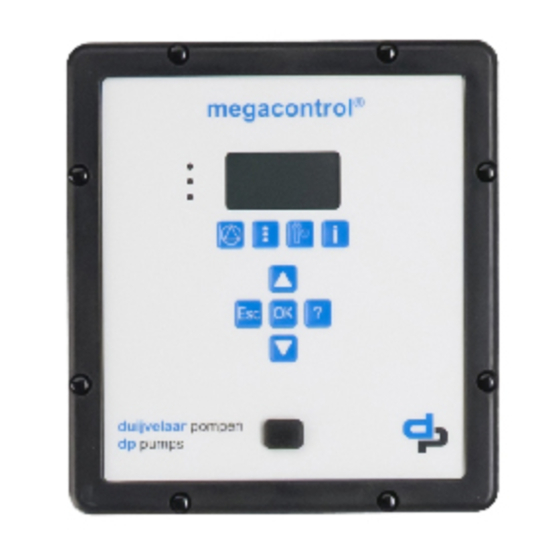
Page 13: Operation
Operation Control panel (HMI) Table 11: Function keys B: Function keys The control panel comprises a back-lit display, You can use the function keys to access the elements at function, navigation, and operating keys, LED’s, and the first menu level directly: Operation, Diagnosis, Settings 2 access points for the service interface. - Page 14 8.1.2 Continuous display D: Service interface RS232 When in operation the most common values, like the The service interface allows a PC / Notebook to be con- system pressure are shown on the display nected with use of the special service port cable. The Meg- continuously.
-
Page 15: Manual Operation Of The Pumps
Manual operation of the ATTENTION If no keys are pressed for ten minutes, pumps the system automatically returns to the default access level. By pressing the Quick access key “Operation”, information like system pressure and pump load can be retrieved. Also, the pump operating mode like 8.1.4 Displaying and changing parameters Automatic, Manual and Disabled can be alternated /... -
Page 16: Retrieve And Reset A Fault
The selected pump will run for a period of 10 seconds and stops. The pump operation mode is changed to Disabled (off) This is to avoid that the pump runs No Water unprotected. When there is a fault that has an open circle, the fault is not active, but has not been acknowledged yet. -
Page 17: Hydro-Unit Configuration
Hydro-unit configuration Hydro-Unit MC Table 16: Specific parameter settings MC Parameter Value ATTENTION 3-3-1 Number of pumps See factory settings 3-2-2-1 3-3-2 Inlet Switch Pressure Level / valve ON-OFF Level / valve prop. 3-3-3 Discharge Fixed Speed 3-5-1 Set point ... -
Page 18: Hydro-Unit Mc
Hydro-Unit MC ++ pressure has been reached, the pumps are switched off one at a time. The minimum run time related switch-off delay is optimized constantly, which results ATTENTION in a considerable energy saving. See factory settings 3-2-2-1 Table 17: Specific parameter settings MC ++ Parameter Value 3-3-1... -
Page 19: Hydro-Unit Mcj
Hydro-Unit MCJ Table 18: Specific parameter settings MCJ Parameter Value ATTENTION 3-3-1 Number of pumps See factory settings 3-2-2-1 3-3-2 Inlet Switch Pressure Level / valve ON-OFF Level / valve prop. 3-3-3 Discharge One Jockey 3-5-1 Set point ..kPa 3-5-3 Bandwidth 3-5-13... -
Page 20: Hydro-Unit Mcf
Hydro-Unit MCF Table 19: Specific parameter settings MCF Parameter Value ATTENTION 3-3-1 Number of pumps See factory settings 3-2-2-1 3-3-2 Inlet Switch Pressure Level / valve ON-OFF Level / valve prop. 3-3-3 Discharge VFD change-over 3-4-3-1 Communication Analog 0-20 mA / 4-20 mA 3-4-3-2 Proportional const. -
Page 21: Hydro-Unit Mcmf
Hydro-Unit MCMF rotation-controlled pumps with delay. A pump is only switched on when 100% or respectively 0% of the speed has been reached. ATTENTION See factory settings 3-2-2-1 Table 20: Specific parameter settings MCMF Parameter Value 3-3-1 Number of pumps 3-3-2 Inlet Switch... - Page 22 Parameter Value 3-4-2-4 Max power Limitation of the maxi- mum power / maxi- mum system load (1 pump is 100%) 3-4-3-1 Communication PumpDrive 2 3-4-3-2 Proportional const. 3-4-3-3 Integral time. 3-4-3-4 Differential time. 3-4-3-5-1 No flow bandwidth Figure 18: 1 pump operation, 1 pump variable 0-1000 kPa 0-2500 kPa 3-4-3-5-2 No flow time...
- Page 23 Table 22: Parameter list PumpDrive 2 Eco Para- Description Help text Factory setting meter 3-1-2-2 Operating Keys Require Direct access to the MAN, OFF, AUTO and FUNC 1=ON Login operating keys can be disabled via this parameter. 3-2-1 Nominal Motor Data 3-2-1-1 Nominal Motor Power Nominal power of motor as per name plate...
-
Page 24: Hydro-Unit Level Control
Para- Description Help text Factory setting meter 3-8-6-1 Digital Input 1 Function Configurable function of digital input 1 No Function Control Digital Bit 0 3-8-6-2 Digital Input 2 Function Configurable function of digital input 2 No Function Control Digital Bit 0 3-8-6-3 Digital Input 3 Function Configurable function of digital input 3... -
Page 25: Explanation Of Parameters
Explanation of parameters 9.8.1 Pressure settings set points 9.8.2 Delta P + correction Figure 22: Pressure settings set points fixed speed Figure 24: 1-pump operation Table 27: Pressure settings set points fixed speed Parameter 3-5-1 Set point 3-5-3 Bandwidth Switch-off pressure Switch-on pressure 2 x bandwidth ID3100... - Page 26 9.8.3 Delta P - correction Table 30: Parameters set points Parameter 3-5-1 Set point 3-5-10 Delta P SP = Set point Figure 27: 1-pump operation New set point Δp = Delta P (always positive) Total number of pumps of the installation Number of pumps switched on 9.8.4 Special input/output...
- Page 27 Fire alarm has higher priority over all other alarms and will turn the pump ON. This is a pulse contact 9.8.4.1 Definable I/O Par. 3-8 Deactivation of this input is only recommended in combination with the use of a VFD per pump. 9.8.4.1.1 Definable inputs Par.
- Page 28 With this function you can activate or deactivate the If this function is activated you must connect an digital input for thermal failure of pump 6 external signal for fire alarm or make a wire bridge Deactivation of this input is only recommended in between the com of the digital inputs and the FIRE combination with the use of a VFD per pump.
- Page 29 With this function the selected digital output (P4/P6 Function level height: and FR4/FR6) follows the digital output of the valve The signal 4-20 mA of the level transmitter is on/off (digital output VA). available to the output and can be used, for instance in a BMS, to indicate the level pressure (4-20 mA) at Function By-pass valve: a distance.
-
Page 30: Break-Unit Megacontrol (Rainwater Recovery)
In system whit a big difference in the flow/capacity of Par. 3-8-2-1 / 3-8-2-6 Selection of the digital output the pumps you can delay the switch on and switch off witch can switch the by-pass valve of the following pump(s) With this configuration of the digital input you can switch an external bypass valve to create a minimal Par. - Page 31 Potable water Figure 30: 1 pump operation Discharge When as a result of an increasing water volume the pressure drops below the pressure set point, one pump will be switched on. When the required system Booster pump(s) pressure has been reached, the pump is switched off. Rain water reservoir The minimum run time related switch-off delay is optimized constantly, which results in a considerable...
- Page 32 9.9.1.2 Delta P + correction 9.9.1.3 Delta P - correction Figure 33: 1-pump on 1 pump stand-by Figure 34: 1-pump on 1 pump stand-by Table 35: Parameters set points Table 36: Parameters set points Parameter Parameter 3-5-1 Set point 3-5-1 Set point 3-5-10 Delta P...
-
Page 33: 10 Parameters
10 Parameters 10.1 Parameter list The parameters of the main menu are related to the standard (default) settings of the installation. The standard (default) settings can be adjusted where necessary and may also be reset whenever required. On the basis of the standard set parameters, an installation will operate as it should. - Page 34 1-1-9.1 Position suppl.valve e n Position of the supply valve proportional 0% ... 100% 1-1-9.2 Position suppl.valve closed e n Position of the supply valve 1 = open 2 = closed open 1-1-10 Power down speed s n Calculated power down speed if NFD is running in energy saving mode 1-1-11 state NFC...
- Page 35 1-2-6-3-4 Starts e n Amount of pump starts of rainwater pump 1 9000000 1-2-6-4 Pump 2 e n Information on the operating status of rainwater pump 2 1-2-6-4-1 Mode e e Off: Rainwater pump 2 is not used. On: Rainwater pump 2 is used 1-2-6-4-2 State...
- Page 36 1-4-20 MPO Shaft Power P3 1-4-21 MPO Shaft Power P4 1-4-22 MPO Shaft Power P5 1-4-23 MPO Shaft Power P6 1-4-24 Debug Mode no debugging 0x0A041 in minutes Bold is Factory setting. 10.1.2 Diagnosis (Quick access button "traffic light") Table 40: Parameter list Megacontrol version 1.7.1 Diagnosis e n Monitoring and diagnosis General...
- Page 37 3-1-1-3-1 Pressure e s Unit for the pressure values feet 3-1-1-3-2 Height e s Unit for the values of the water level height in the receiver tank (storage tank at suction side) 3-1-1-3-3 Temperature °C e s Unit of the temperature when temperature sensor °F is available (WSD functionality) 3-1-1-4...
- Page 38 #0-0 Load loc. param. Reset ok c c Load locally saved parameters No set available 3-2-2-4 Save custom. setting c c Save of the customer setting 3-2-2-5 Save factory setting Save of the factory settings 3-2-2-6 Default setting s s Reset to default setting 3-2-2-6.1.1 #0-0 Reset default param.
- Page 39 3-3-4 e s Setting of the applicable configuration of the WSD: 1 tank (membrane tank refreshments and ambient temp.) 2 tanks 3 tanks 1 tank + temp 2 tanks + temp 3 tanks + temp Temperature 3-3-5 Leakage detection e s Leakage detection 3-3-6 MPO Functionality s s Synchron pump operation...
- Page 40 3-4-1-4-8-2 Threshold 1 OFF e s Water level at which the relays output becomes ""low"" 199.9 3-4-1-4-8-3 Threshold 2 ON e s Water level at which the relays output becomes ""high"" 199.9 3-4-1-4-8-4 Threshold 2 OFF e s Water level at which the relays output becomes ""low""...
- Page 41 3-4-1-5 Auto. Setpoint Redu. e n Automatic setpoint reduction by low inlet pressure 3-4-1-5-1 ASR function e s Automatic setpoint reduction function 3-4-1-5-2 Switch on point e s The pumps are switched On, if inlet pressure is above switch-On point for more then Switch-On time 3-4-1-5-3 Inlet Set point...
- Page 42 3-4-2-1 Sensor press. 4 mA -100 e s Measured value at 4mA 1000 3-4-2-2 Sensor press. 20 mA e s Measured value at 20mA 1000 9999 3-4-2-3 Pumps ON sensor fail e s Number of pumps that is started in case of a fail- ure of the pressure sensor on the discharge side.
- Page 43 3-4-3-5-4 No flow max. power s s No flow detection is active below this Pump load in 3-4-3-9 VFD Ramp-Up e s Setting of the ramp-up of the VFD 3-4-3-10 VFD Ramp-Down e s Setting of the ramp-down of the VFD 3-4-3-11 VFD min.
- Page 44 3-4-3-27 Slip Compensation -400 e s Slip Compensation of the VFD 3-4-3-28 Torque Characterist. Constant torque Low,Medium,High Low, const. start Medium, const. start High, const. start Special Motor Mode 3-4-3-29 Fuction Relay 1 No Function Drive ready Drive running 3-4-3-30 Fuction Relay 2 No Function Drive ready...
- Page 45 3-4-5-6-3 Power 3 3-4-5-6-4 Power 4 3-4-5-7 Motor settings e n Motor Paramters settings 3-4-5-7-1 Rated Motor Power e s Motor rating plate 3-4-5-7-2 Rated Motor Speed e s Motor rating plate 1425 3600 3-4-5-7-3 Rated Freq e s Motor rating plate 3-4-5-7-4 Rated Current e s Motor rating plate...
- Page 46 3-5-14 Low pressure action e c Selection parameter to define the action at system under-pressure (shut down or signal only) 3-5-14.1.1 #0-0 Low pressure action shutdown pumps e c Selection parameter to define the action at system only message under-pressure (shut down or signal only) 3-5-15 Shut down RDP -100...
- Page 47 3-6-15-1 Switch on delay c c Debounce time to avoid switching On the pump, when actual value is less then setpoint minus bandwidth 3-6-15-2 Switch off delay c c Debounce time to avoid switching Off the pump, when actual value is more then setpoint plus bandwidth Time/Date e n Date and time...
- Page 48 3-7-8-1 Adaptation mode e c Setting the adaptation mode of the alternative set- Adapt ON/OFF ev. point. Adapt.ON/OFF per 3-7-8-2 Change on/off times e c The alternation to an alternative setpoint becomes active/ will be undo at the selected time. 3-7-8-2.1.1 #0-0 Hours adapt setp.ON e c Setting the hours at which the alternation to a alternative setpoint becomes active...
- Page 49 3-7-10.1.1 #0-0 Month adapt lev Off e c The level setpoint alternation will be undo at the January selected Month's February March April June July August September October November December 3-7-10.1.2 #0-1 Day adapt level Off e c The level setpoint alternation will be undo at the selected day of the selected Month's) 3-7-11 Maintenance interval...
- Page 50 3-8-1-10 Function RDP s s Functionality of digital input RDP 3-8-1-11 Function TFR s s Functionality of digital input TFR 3-8-1-12 Function TVA s s Functionality of digital input TVA 3-8-1-13 Functionality OFF s s Evaluation of digital input OFF 3-8-1-14 Function FIRE s s Functionality of digital input FIRE...
- Page 51 3-8-2-6 Conf. FR6 (DO) None s s Configuration of digital output FR6 Threshold relay 1 Threshold relay 2 Input valve By-pass valve RDP Alarm O/P Low water level Operational avail. 3-8-2-7 Opert./Fail. Relay 3-8-2-8 Conf. FR (AO) None s s Configuration of analog output FR (AO) System pressure System load Level height...
- Page 52 Failure VFD Br. Wire Sens.dis Br. Wire Sens.Inl Fail. several FCs Leakage Eeprom HW Error Manual off Pump # Manual On Pump # More Pumps off Internal Failure P# Mains Failure P# Over voltage P# Under voltage P# Overload Failure P# Brake resistor P# Temp.
- Page 53 3-11 Energy Saving Mode s n Energy Saving Mode 3-11-1 Energy Saving Mode s s Energy Saving Mode 3-11-2 direct off s s Energy Saving Mode without NFD functionality is executed 3-11-3 Power down speed % s s Calculated power down speed if NFD is running in energy saving mode in % 3-11-4 time direct off...
- Page 54 3-14-2 Open delay e s Time delay for opening the valve 3-14-3 Close delay e s Time delay for closing the valve 3-14-4 Temperature e s Above this temperature the valve will be opened 3-14-5 Flush Time e s Time during the valve is opened 3-14-6 Attemps in 24Hrs e s Number of attempts to open valave before an...
- Page 55 4-3-1 HMI Serial Number 4-3-2 HMI FW-Version 4-3-3 HMI FW-Revision 4-3-4 HMI HW-Revision Profibus Info 4-4-1 PB FW-Version 4-4-2 PB FW-Revision 4-4-3 PB HW-Revision Modbus Info 4-5-1 MB FW-Version 4-5-2 MB FW-Revision 4-5-3 MB HW-Revision Bold is Factory setting. 10.1.5 Quick menu (Quick access button "OK") Table 43: Parameter list Megacontrol version 1.7.1...
- Page 56 3-4-1-4-9-2 Level 1 closed e s Level in the receiver tank at which the supply valve is closed 99.9 3-4-1-4-10-1 Level setpoint 1 e s Maximum level in the receiver tank at which the proportional valve is fully closed 99.9 3-4-1-4-10-3 Hysteresis e s Differential level in the receiver tank at which the...
- Page 57 3-6-2 Min. run time e c The minimum time of the pump to run. (the run time correction will not drop below this value) 3-6-5 Start delay e s Start delay to switch the pumps on when pressure remains low 3-6-6 Stop delay e s Stop delay to switch the pumps off when pressure...
-
Page 58: 11 Faults
11 Faults 11.1 Failure messages Megacontrol Table 44: Faults list Megacontrol Failure message: Explanation: Failure output: Failure PT. Dis. Failure Pressure Transmitter discharge side (value >20mA) replace PT and reset system Urgent Sys. press.to low System pressure too long under minimum value (3-5-13) Urgent Sys press.to high System pressure too long above maximum value (3-5-11) - Page 59 Failure message: Explanation: Failure output: Internal Failure P# Not urgent Mains Failure P# Not urgent Over voltageP# Not urgent Under voltage P# Not urgent Overload Failure P# Not urgent Brake resistor P# Not urgent Temp. Failure P# Not urgent ATM Failure P# Not urgent Flushing Not urgent...
-
Page 60: Failure Messages Danfoss Vfd
11.2 Failure messages Danfoss VFD ATTENTION The error codes are displayed in the error log of the Megacontrol. For specific information about the error codes please consult the (technical) documentation of the VFD concerned. Table 45: VLT 2800 Error code: Explanation: Warning: Alarm: Trip lock: Live zero error (LIVE ZERO ERROR) - Page 61 Error code: Explanation: Warning: Alarm/Trip: Alarm/Trip Lock: Torque limit Over Current Earth fault Hardware mismatch Short Circuit Control word time out Internal fan fault External fan fault Brake resistor short-circuit Brake resistor power limit Brake chopper fault Brake check failed Heatsink temp Motor phase U missing Motor phase V missing...
- Page 62 Error code: Explanation: Warning: Alarm/Trip: Alarm/Trip Lock: Safe Stop Activated Power Card Temp Illegal FC configuration PTC 1 safe stop Dangerous Failure Safe Stop Auto Restart Power unit setup Illegal PS config Drive Initialised to Default Value Analog input 54 wrong settings No flow Dry pump End of curve...
- Page 63 Error code: Explanation: Warning: Alarm: Trip lock: Error Power board over temp Motor phase U missing Motor phase V missing Motor phase W missing Internal fault Earth fault Control Voltage Fault AMT check U and I AMT low I Current limit Mechanical Brake Low Drive Initialised to Default Value The connection between drive and LCP is lost...
-
Page 64: 12 Annexes
12 Annexes 12.1 Megacontrol Table 48: Technical specifications Item Value Type of control Megacontrol Article number Megacontrol 1-3 pumps 77870550 Article number Megacontrol 1-6 pumps 77870551 Dimensions HxWxD [mm] 306.5 x 187 x 72.5 Connecting voltage [V] 230 ± 5% Frequency [Hz] 50/60 Relay outputs [A]... -
Page 65: Built-In Diagram
12.2 Built-in diagram ID 2970/29052007 Figure 36: Built-in diagram 12.3 Electrical connections Additional information on the RS485 bus: J302 to J301 and the use of a filter on the coil of contactors / auxiliary relays. See chapter: 7.2.3 Using contactors ATTENTION Connections for bus communication (RS485 A/B) to frequency converter are moved from J302 to J301 (see drawing fig.: 37 Megacontrol Lay-out 1-3 (1-6) pumps) - Page 66 ID2971/07062007 Figure 37: Megacontrol Lay-out 1-3 (1-6) pumps * refers to table 49 Electrical connections...
- Page 67 Table 49: Electrical connections Code: Connection: Code: Connection Termination resistor Failure urgent Termination resistor Common GND2 Common WSD sensor 1 Start VFD 1 Common WSD sensor 2 Common Start VFD 2 WSD sensor 3 Common Common Temperature sensor Start VFD 3 Common Start pump 1 Start pump 2...
-
Page 68: Ec Declaration Of Conformity
12.4 EC declaration of conformity Undersigned: DP-Pumps Kalkovenweg 13 2401 LJ Alphen aan den Rijn, The Netherlands Tel: (+31)(0)-172-48 83 88 Declares as manufacturer entirely on his own responsibility, that the product(s): Product: Control unit Type: Megacontrol to which this declaration refers, is in accordance with the following standards:... - Page 72 P.O. Box 28 2400 AA Alphen aan den Rijn (NL) t (+31-172) 48 83 88 f (+31-172) 46 89 30 dp@dp-pumps.com www.dp-pumps.com 06/2017 BE00000508-D / EN Original instructions Can be changed without prior notice...
Need help?
Do you have a question about the Megacontrol Series and is the answer not in the manual?
Questions and answers