nvent SPECTRACOOL N28 Instruction Manual
Hide thumbs
Also See for SPECTRACOOL N28:
- Instruction manual (44 pages) ,
- Instruction manual (44 pages)

Related Manuals for nvent SPECTRACOOL N28


Summary of Contents for nvent SPECTRACOOL N28
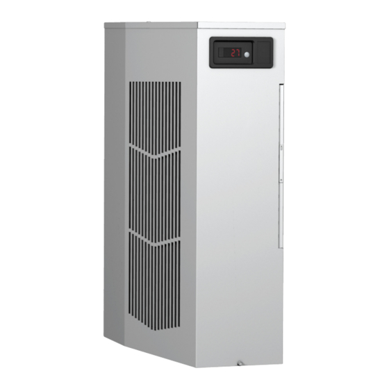
- Page 1 SPECTRACOOL Air Conditioner n28 Model INSTRUCTION MANUAL Rev. G © 2020 nVent 89115550 P/N 89115550...
-
Page 2: Table Of Contents
NOTE: Some of the information in this manual may not apply if a special unit was ordered. If additional drawings for a special unit are necessary, they have been inserted. Contact Pentair Equipment Protection if further information is required. WARRANTY AND RETURN POLICY https://hoffman.nvent.com/en/hoffman/warranty-information © 2020 nVent 89115550 - 2 -... -
Page 3: Receiving The Air Conditioner
Damage evident upon receipt should be noted on the freight bill. Damage should be brought to the attention of the delivering carrier -- NOT to nVent Equipment Protection -- within 15 days of delivery. Save the carton and packing material and request an inspection. Then file a claim with the delivering carrier. -
Page 4: For Cooling (75-100 F Range)
The unit will remain electrified when the door switch is operated with the evaporator fan continuing to operate, and potentially, if temperatures are low enough, the heater may continue to operate on outdoor models. © 2020 nVent 89115550 - 4 -... -
Page 5: Schematics And Wiring Diagrams For Thermostat Control
SCHEMATICS AND WIRING DIAGRAMS FOR THERMOSTAT CONTROL GENERIC 115V 1-PHASE SCHEMATIC (ACTUAL UNIT OPTIONS MAY VARY) 89074302 GENERIC 230V 1-PHASE SCHEMATIC (ACTUAL UNIT OPTIONS MAY VARY) © 2020 nVent 89115550 - 5 -... -
Page 6: Generic 460V 1-Phase Schematic (Actual Unit Options May Vary)
GENERIC 460V 1-PHASE SCHEMATIC (ACTUAL UNIT OPTIONS MAY VARY) © 2020 nVent 89115550 - 6 -... -
Page 7: Generic 115V 1-Phase Wire Diagram (Actual Unit Options May Vary)
WHT41 TO THERMAL BLK40 DISPLAY BRN26 BLK11 BLK27 HEATER BLK28 BLU29 LIMIT SWITCHES BLK14 ENCLOSURE WHT15 ENC. AMB. START CAPACITOR AMBIENT IMPELLER 0.L. BLK12 BLK20 COMPRESSOR 89073631 COMP HTR OR C/E (OPTIONAL) (OPTIONAL) © 2020 nVent 89115550 - 7 -... -
Page 8: Generic 230V 1-Phase Wire Diagram (Actual Unit Options May Vary)
GENERIC 230V 1-PHASE WIRE DIAGRAM (ACTUAL UNIT OPTIONS MAY VARY) © 2020 nVent 89115550 - 8 -... -
Page 9: Generic 460V 1-Phase Wire Diagram (Actual Unit Options May Vary)
GENERIC 460V 1-PHASE WIRE DIAGRAM (ACTUAL UNIT OPTIONS MAY VARY) © 2020 nVent 89115550 - 9 -... -
Page 10: Dimensional Drawing
DIMENSIONAL DRAWING WITH THERMOSTATS 89068456 © 2020 nVent 89115550 - 10 -... -
Page 11: Installation Instructions
24 VAC terminal strip by noting the locations on the correct wiring diagram. 8. Set thermostat for required cabinet temperature. Refer to Sequence of Operation on page 4 for thermostat adjustment and operation. Surface Mount Figure 1 Cut-out Drawing © 2020 nVent 89115550 - 11 -... -
Page 12: Remote Access Control (Optional)
Evaporator Fan On Start-up Request AMBER Not Used Not Used AMBER Not Used Not Used AMBER Heater Active Not Used Alarm Active Not Used AMBER Controller Active Not Used AMBER Not Used Not Used © 2020 nVent 89115550 - 12 -... -
Page 13: Displaying And Changing Program Variables
The Remote Access Control has a normally open dry contact alarm output with a resistive load rating of 250 VAC at 3 amps. Two yellow 18 AWG wires located at the back of the air conditioner provide a connection to this output. © 2020 nVent 89115550 - 13 -... -
Page 14: Alarm Input Connection
Read and change the state of IP addressing (static or dynamic) • Read current Alarm Status SOFTWARE AND CONFIGURATION FILE DOWNLOADS The PC Interface Tool, MIB file, EDS file, EtherNet_IP Object file and Coil_Register file can be downloaded from www.hoffmanonline.com. © 2020 nVent 89115550 - 14 -... -
Page 15: Using The Pc Interface Tool
To change to statically assigning IP Address Mode Uncheck Use DHCP Server checkbox • • Enter Device IP Address, Subnet Mask, Gateway IP Address, Trap IP Address and Community • Click Load Ethernet Info button © 2020 nVent 89115550 - 15 -... -
Page 16: Ethernet Communication Mode
Enter Device IP Address, Subnet Mask, Gateway IP Address, Trap IP Address and Community • Click Load Ethernet Info button ALARM LOG ACCESSIBLE WITH SNMP Using custom software with the provided MIB file gives the ability to view a log of the last 25 alarms • © 2020 nVent 89115550 - 16 -... -
Page 17: Remote Access Control Pin-Out
ID GND Y (na) U2 INPUTS GND (na) T1, EVAP IN THERMISTOR T2, EVAP OUT THERMISTOR T1, T2 GND CONTROLLER POWER BLK40 CONTROLLER POWER WHT41 POWER GROUND BLACK U3 DATA DIRECTION GREEN DATA WHITE © 2020 nVent 89115550 - 17 -... -
Page 18: Schematics And Wiring Diagrams For Remote Access Control
SCHEMATICS AND WIRING DIAGRAMS FOR REMOTE ACCESS CONTROL GENERIC 115V 1-PHASE SCHEMATIC (ACTUAL UNIT OPTIONS MAY VARY) GENERIC 230V 1-PHASE SCHEMATIC (ACTUAL UNIT OPTIONS MAY VARY) 89115043 REV. A © 2020 nVent 89115550 - 18 -... -
Page 19: Generic 460V 1-Phase Schematic (Actual Unit Options May Vary)
GENERIC 460V 1-PHASE SCHEMATIC (ACTUAL UNIT OPTIONS MAY VARY) 89115043 REV. A © 2020 nVent 89115550 - 19 -... -
Page 20: Generic 115V 1-Phase Wire Diagram For Remote Access Control (Actual Unit Options May Vary)
GENERIC 115V 1-PHASE WIRE DIAGRAM FOR REMOTE ACCESS CONTROL (ACTUAL UNIT OPTIONS MAY VARY) © 2020 nVent 89115550 - 20 -... -
Page 21: Generic 230V 1-Phase Wire Diagram For Remote Access Control (Actual Unit Options May Vary)
GENERIC 230V 1-PHASE WIRE DIAGRAM FOR REMOTE ACCESS CONTROL (ACTUAL UNIT OPTIONS MAY VARY) 89115041 REV.A © 2020 nVent 89115550 - 21 -... -
Page 22: Generic 460V 1-Phase Wire Diagram For Remote Access Control (Actual Unit Options May Vary)
GENERIC 460V 1-PHASE WIRE DIAGRAM FOR REMOTE ACCESS CONTROL (ACTUAL UNIT OPTIONS MAY VARY) 89115546 REV.A © 2020 nVent 89115550 - 22 -... -
Page 23: Dimensional Drawing
DIMENSIONAL DRAWING WITH REMOTE ACCESS CONTROL 89082927 © 2020 nVent 89115550 - 23 -... -
Page 24: Installation Instructions With Remote Access Control
Electrical circuit should be fused with slow blow or HACR circuit breaker. 6. Set controller setpoints for required cabinet temperature. Refer to Displaying and Changing Program Variables on page 13 for setpoint adjustment and operation. Surface Mount Figure 2 Cut-out Drawing © 2020 nVent 89115550 - 24 -... -
Page 25: Maintenance
1. Flush the filter with warm water from the exhaust side to the intake side. DO NOT USE CAUSTICS. 2. After flushing, allow filter to drain. Placing it with a corner down will assure complete drainage. © 2020 nVent 89115550... -
Page 26: Condenser And Evaporator Air Movers
CAUTION Operation of the air conditioner in areas containing airborne caustics or chemicals can rapidly deteriorate filters, condenser coils, blowers and motors, etc. Contact nVent Equipment Protection for special recommendations. REFRIGERANT LOSS Each air conditioner is thoroughly tested prior to leaving the factory to insure against refrigeration leaks. Shipping damage or microscopic leaks not found with sensitive electronic refrigerant leak detection equipment during manufacture may require repair or recharging of the system. -
Page 27: Unit Characteristics
Evaporator Unit Amps(A) In(°F) Delta(°F) Delta(°F) 65-80 7-7.4 15-22 13-28 N280416GXXX 80-100 7.4-8.6 21-25 14-24 65-80 3.1-3.7 17-25 15-27 N280426GXXX 80-100 3.4-4.1 19-29 14-31 65-80 1.5-1.9 17-25 15-27 N280446GXXX 80-100 1.7-2.1 19-29 14-31 © 2020 nVent 89115550 - 27 -... -
Page 28: Service Data
10106116SP Transformer, Input Power 101006111SP Overload 89114723SP 89114724SP 89114724SP Controller, Basic 89075653SP Thermistor 89075654SP Bridge Rectifier 89087424SP Controller Wires with pins (24) 89083091SP Communication Board 89082033SP Communication Cable 89080313SP 315 mA Fuse 89085115SP © 2020 nVent 89115550 - 28 -... -
Page 29: N280416Gxxx Pressure Tables
N280416GXXX PRESSURE TABLES N280416GXXX 50hz L=SUCTION (± 5PSIG); H=HEAD (-10/+20PSIG) ENCLOSURE TEMPERATURE (°F) °F N280416GXXX 60hz L=SUCTION (± 5PSIG); H=HEAD (-10/+20PSIG) ENCLOSURE TEMPERATURE (°F) °F © 2020 nVent 89115550 - 29 -... -
Page 30: N280426Gxxx Pressure Tables
N280426GXXX PRESSURE TABLES N280426GXXX 50hz L=SUCTION (± 5PSIG); H=HEAD (-10/+20PSIG) ENCLOSURE TEMPERATURE (°F) °F N280426GXXX 60hz L=SUCTION (± 5PSIG); H=HEAD (-10/+20PSIG) ENCLOSURE TEMPERATURE (°F) °F © 2020 nVent 89115550 - 30 -... -
Page 31: N280446Gxxx Pressure Tables
Factory Charge 283 Grams 312 Grams Füllmenge durch Hersteller 283 Gramm 312 Gramm Opłata Fabryczna 283 Gramów 312 Gramów Equivalent 0.40 Tons 0.45 Tons Equivalent 0,40 Tonnen 0,45 Tonnen Ekwilalent 0,40Tony 0,45 Tony © 2020 nVent 89115550 - 31 -... -
Page 32: Trouble Shooting
(replace upper access panel for safety). This will activate the switch in the thermostat. Turn the power on and if all impellers and the compressor come on, the thermostat needs to be replaced. © 2020 nVent 89115550 - 32 -... -
Page 33: Symptoms And Possible Causes - Thermostat Version
Unit blows breakers Short in system Drain plugged Drain tube kinked Getting water in enclosure Enclosure not sealed (allowing humidity in) Mounting gasket damaged For additional technical support, contact nVent Equipment Protection at 800-896-2665. © 2020 nVent 89115550 - 33 -... -
Page 34: Basic Air Conditioning Trouble Shooting Check List - Remote Access Control Version
» Unit still in Recycle Time Delay mode Wait and/or heat » Enclosure temperature below cooling enclosure thermistor T1 setpoint temperature 6. The compressor and the condenser (Ambient or “HOT” air) impeller(s) should turn on. Is there adequate airflow? © 2020 nVent 89115550 - 34 -... -
Page 35: Symptoms And Possible Causes - Remote Access Control Version
Unit blows breakers Short in system Drain plugged Drain tube kinked Getting water in enclosure Enclosure not sealed (allowing humidity in) Mounting gasket damaged For additional technical support, contact nVent Equipment Protection at 800-896-2665. © 2020 nVent 89115550 - 35 -... - Page 36 Rev. G © 2020 nVent 89115550 P/N 89115550...
Need help?
Do you have a question about the SPECTRACOOL N28 and is the answer not in the manual?
Questions and answers