MICRO-EPSILON scanCONTROL 25 Series Assembly Instructions Manual
Hide thumbs
Also See for scanCONTROL 25 Series:
- Operating instructions manual (60 pages) ,
- Operating instructions manual (64 pages)
Table of Contents
Advertisement
Quick Links
1.
Warnings
Connect the power supply and the display/output device according to the safety
regulations for electrical equipment. The supply voltage must not exceed the specified
limits.
> Risk of injury, damage to or destruction of the sensor
> Avoid shocks and impacts to the sensor. Avoid constant exposure of the sensor to
dust and splashes of water. Avoid exposure of sensor to aggressive media (deter-
gents, cooling emulsions).
> Damage to or destruction of the sensor
2.
Notes on CE Marking
The following apply to the scanCONTROL 25xx measuring system:
- EU Directive 2014/30/EU
- EU Directive 2011/65/EU
The measuring system is designed for use in industrial applications.
The measuring system satisfies the requirements if the guidelines in the operating inst-
ructions are maintained in installation and operation.
3.
Proper Environment
- Protection class:
- Temperature range:
ƒ Operation:
ƒ Storage:
- Humidity:
scanCONTROL 25xx
Assembly Instructions
scanCONTROL
IP65
0 ... +45 °C (+32 ... +113 °F), when air is circulating freely
-20 ... +70 °C (-4 ... +158 °F)
5 - 95 % (non-condensing)
2500 / 2510
Page 1
Advertisement
Table of Contents

Related Manuals for MICRO-EPSILON scanCONTROL 25 Series


Summary of Contents for MICRO-EPSILON scanCONTROL 25 Series
- Page 1 Assembly Instructions scanCONTROL 2500 / 2510 Warnings Connect the power supply and the display/output device according to the safety regulations for electrical equipment. The supply voltage must not exceed the specified limits. > Risk of injury, damage to or destruction of the sensor >...
-
Page 2: Laser Safety
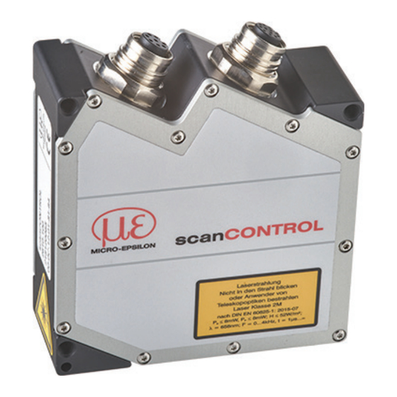
Laser Safety The scanCONTROL 25xx sensors operate with a semiconductor laser with a wavelength of 658 nm (visible/red). Operation of the laser is indicated visually by the LED on the sensor, see operating instructions Chap. 3.3. When operating the scanCONTROL 25xx sensors, the relevant regulations according to IEC 60825, Part 1 of 05/2014 and the applicable accident prevention regulations must be followed. -
Page 3: Beam Attenuator
Laser Class 3B The sensors with the /3B option fall within laser class 3B. The laser is operated on a pulsed mode, the maximum optical power is ≤ 50 mW. Laser radiation. Wear suitable protective glasses. Injury of the eyes and the skin are possible. Attach the following warning labels to the cover (front and rear side) of the sensor housing: In addition, the following information la-... - Page 4 Connections, LED Indication 1 Ethernet port 2 Multifunction port (power supply, I/O) Multifunction Port Designation Sensor Cable color Notes connector pin PCR3000-x + 11 V - 30 V DC (rated value 24 V); max. 500 mA Blue +Laser on/off White available with SI option -Laser on/off Brown...
- Page 5 Trigger, Encoder, Mode Switching The switching inputs of the multifunction port can either be used for encoder input, trigger input or to load previously stored user modes. The signal levels are switchable for all switching inputs between LLL (TTL logic) and HLL (HTL logic): - LLL level: Low 0 V …...
-
Page 6: Led State
> Damage to the sensor and/or Ethernet card! - A fixed IP address can be assigned. Use the sensorTOOL program to specify the sensor settings described above. The program is available online at www.micro-epsilon.com/download/software/sensor- TOOL.exe. LED Indication LED laser on Meaning... - Page 7 Mount the sensor according to the installation instructions. Install the software. You will find the software online on the product website of the sensor or in the download area: www.micro-epsilon.com/2D_3D/la- ser-scanner/Software/downloads/ Follow the dialog through the installation process: A. Reading the installation help B.
- Page 8 First Profile Now start the scanCONTROL Configuration Tools software. Click Display Profiles in the main window. If the software shows the error message No scanCONTROL found in the status line, please check the Ethernet connection between scanCONTROL and the PC. On the left side you can adjust the settings for your measurement task, the right side shows the profile data and further information about the measurement.
- Page 9 - RS422 interface ƒ Modbus RTU protocol ƒ Transmission of measurement values in ASCII format 2D/3D Gateway 2D/3D Gateway allows for scanCONTROL SMART sensors to be integrated into various fieldbus systems: - PROFINET - EtherNet/IP - EtherCAT All measurement results obtained from the profile evaluation performed by a scanCONTROL SMART sensor can be transmitted to a PLC via one of these fieldbus systems.
- Page 10 scanCONTROL 25xx with 2D/3D Output Unit for PLC Connection Status of operating voltage 13 14 - Power contacts LINK ETHERNET ACT 1 - System LINK Data contacts Ñ System supply (OUT) 0: WBM 255: DHCP 24 V Supply via power contacts System supply (In) 24 V 750-626...
- Page 11 Status Status 13 14 13 14 DO 1 DO 2 Function DO 8 Error DO 7 Data A1 A2 A1 A2 Data contacts contacts DO 1 DO 2 AO 1 AO 2 A3 A4 DO 4 DO 3 A5 A6 A3 A4 DO 5 DO 6...
-
Page 12: Unpacking, Included In Delivery
You can find more information about the sensor in the operating instructions. They are available online at: www.micro-epsilon.com/download/manuals/man--scanCONTROL-25xx--en.pdf www.micro-epsilon.com MICRO-EPSILON Messtechnik GmbH & Co. KG Koenigbacher Str. 15 94496 Ortenburg / Germany, Tel. +49 (0) 85 42/1 68-0 Your local contact: www.micro-epsilon.com/contact/worldwide/...
Need help?
Do you have a question about the scanCONTROL 25 Series and is the answer not in the manual?
Questions and answers