Table of Contents
Advertisement
Quick Links
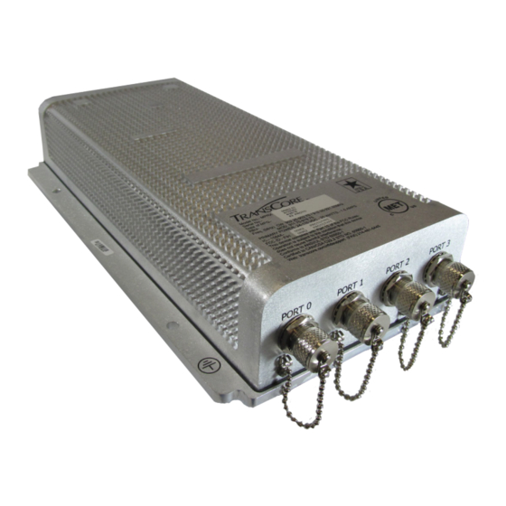
TransCore's Multiprotocol Reader Extreme (MPRX) is a radio frequency
identification (RFID) reader that is specifically designed for harsh
environment applications.
Purpose of This Guide
This guide provides site planning and testing, installing, and operating instructions for
TransCore's Multiprotocol Reader Extreme (MPRX) System, which reads Association of
American Railroads (AAR) formatted tags and TransCore Super eGo® (SeGo) protocol tags.
Before you begin installing the MPRX, TransCore recommends that you familiarize yourself
with this manual.
Intended Audience
This document is intended for use by authorized TransCore MPRX dealers, installers,
and service personnel. Because the MPRX has no operator or end-user serviceable
components or features, no end-user manual or operator guide exists. Once the system
is set up and tested by the authorized installer, MPRX operation requires no end-user
intervention. Information in this document is subject to change and does not represent a
commitment on the part of TransCore, LP.
Multiprotocol
Reader Extreme (MPRX)
System Guide
16-0079-001 Rev A 11/16
Trusted Transportation Solutions
Advertisement
Table of Contents

Related Manuals for TransCore Multiprotocol Reader Extreme


Summary of Contents for TransCore Multiprotocol Reader Extreme
- Page 1 This guide provides site planning and testing, installing, and operating instructions for TransCore’s Multiprotocol Reader Extreme (MPRX) System, which reads Association of American Railroads (AAR) formatted tags and TransCore Super eGo® (SeGo) protocol tags. Before you begin installing the MPRX, TransCore recommends that you familiarize yourself with this manual.
- Page 2 System Guide © 2016 TransCore, LP. All rights reserved. TRANSCORE, AMTECH, EGO, TRU, and ENCOMPASS are registered trademarks and are used under license. All other trademarks are the property of their respective owners. Contents are subject to change. Printed in the U.S.A.
- Page 3 Unauthorized modification may void the equipment authorization from the FCC and will void the warranty. USE OF SHIELDED CABLES AND GROUNDING 47 CFR §15.27(A) NOTE: Shielded cables and earth grounding the unit is recommended for this equipment to comply with FCC regulations. TRANSCORE, LP TransCore Proprietary...
- Page 4 UTILISATION DE CÂBLES BLINDÉS ET MISE À LA TERRE 47 CFR §15.27(A) REMARQUE : Il est recommandé d’utiliser des câbles blindés et une mise à la terre avec cet appareil afin de répondre aux réglementations de la FCC TRANSCORE, LP ÉTATS-UNIS TransCore Proprietary...
- Page 5 L'exploitation est autorisée aux deux conditions suivantes : l'appareil ne doit pas produire de brouillage, et l'utilisateur de l'appareil doit accepter tout brouillage radioélectrique subi, même si le brouillage est susceptible d'en compromettre le fonctionnement. TransCore Proprietary...
- Page 6 Occupational (Controlled) and General Population/ Public (Uncontrolled), the recommended levels for each of the agencies are presented in the next sections with TransCore’s recommendations for safety in the last section. OSHA (Occupational Safety and Health Administration) OSHA (an agency of The United States of America) legislates in the Code of Federal Regulations (CFR) Title 29 Part 1910 Subpart G 1910.97 titled “Nonionizing radiation”, a maximum safe exposure...
- Page 7 The MPE minimum distances are 18in (45cm) for the Controlled environment and 47in (120cm) for the General Public/Uncontrolled environment. TransCore Recommendation on MPE (Maximum Permissible Exposure) The calculated power densities and MPE distance for each of the agencies respective to the environment is shown below.
- Page 8 The antenna should be installed at least 42in (106cm) from the General Population/ Public i.e. Uncontrolled Environment. Maintenance personnel (i.e. Occupational/Controlled Environment) must remain at least 16in (40cm) from the antenna and limit their time in the environment to 6 minutes when the system is operating. TransCore Proprietary viii...
- Page 9 (accès contrôlé) ou pour la population générale/le grand public (accès non contrôlé), TransCore présente les niveaux recommandés par chaque organisme dans ses recommandations sécuritaires détaillées dans la dernière section.
- Page 10 45 cm (18 po) pour l’environnement professionnel/contrôlé et de 120 cm (47 po) pour le grand public/environnement non contrôlé. Recommandations de TransCore sur les limites d’exposition maximale autorisée (normes MPE) Les densités de puissance et la distance MPE calculées par chaque organisme pour un environnement donné...
- Page 11 Le personnel d’entretien (c’est-à-dire dans un environnement professionnel/contrôlé) doit rester à au moins 40 cm (16 po) de l’antenne et limiter son temps d’exposition à 6 minutes lorsque l’appareil est en fonctionnement. TransCore Proprietary...
-
Page 12: Table Of Contents
Command Response Conventions ........5–3 i–i TransCore Proprietary... - Page 13 MPRX to TRU Connection......... 10–3 Chapter 11 AT5720 Check Tag-to-MPRX Assembly....11–2 TransCore Proprietary...
- Page 14 Tag Data Formats ..........E–4 TransCore Proprietary...
- Page 15 Figure 4 – 8 Sample Read Zone Marking Pattern ..............4–15 Figure 8 – 1 Connection Description Dialog Box ................8–4 Figure 8 – 2 Phone Number Dialog Box ................... 8–4 Figure 8 – 3 COM 1 Properties Dialog Box ..................8–5 Figure 8 – 4 Hyper Terminal Main Screen..................8–6 Figure 8 – 5 Sign-on Message ......................8–7 TransCore Proprietary...
- Page 16 Figure 11 – 4 Two Check Tag Assemblies Connected to Terminal Strip .........11–4 Figure 11 – 5 Securing Terminal Strip into Connector Housing ..........11–5 Figure 11 – 6 Plastic Nuts with Grommets ..................11–5 Figure 11 – 7 Nylon Cap Securely Fastened in Unused Port ..........11–6 Figure 11 – 8 Check Tag Assembly Secured to MPRX Port .............11–6 TransCore Proprietary...
- Page 17 Table 7 – 6 Unique ID Code Criteria ....................7–11 Table 7 – 7 Select Valid Code Commands and Frames ............7–12 Table 7 – 8 Flow Control Commands ...................7–25 Table 7 – 9 RF Control Commands ....................7–26 Table 7 – 10 RF Attenuation Command Variables ..............7–27 Table 7 – 11 Select RF Frequency Commands ................7–29 TransCore Proprietary...
- Page 18 Table C – 3 MPRX SENSE Communications Cable Pin Designations ........C–4 Table D – 1 MPRX Default Configuration Settings ..............D–2 Table D – 2 MPRX Commands Listed Numerically ..............D–4 Table D – 3 MPRX Commands Listed Alphabetically ............... D–14 Table E – 1 SeGo Protocol Tags ...................... E–2 Table E – 2 AAR-formatted Tags ........................E–3 TransCore Proprietary...
-
Page 19: Chapter 1 Introduction
Chapter 1 Introduction... -
Page 20: Table 1 - 1 Mprx System Guide Overview
Multiprotocol Reader including pre-installation testing, installing the MPRX in a railside hut or NEMA Extreme enclosure, connecting power and communications, connecting to TransCore’s Train Recording Unit (TRU™), and marking the read zone Chapter 5 – General Provide reference information on various software-related topics Software Information Chapter 6 –... -
Page 21: Table 1 - 2 Typographical Conventions
Zero-value pointers. Null-terminated string refers to strings of printable ASCII characters with a zero-value byte placed in memory directly after the last printable character of the string. This procedure might cause harm to the equipment and/or the user. TransCore Proprietary 1–3... -
Page 22: Licensing Requirements
902.25 to 903.75 MHz and 910.00 to 921.50 MHz. The user is responsible for filing the FCC license according to FCC regulations, but the TransCore dealer will provide assistance and support as necessary to complete these forms. Forms are available online at the FCC internet site http://wireless.fcc.gov/uls. For further information on obtaining the license contact TransCore. - Page 23 MPRX TransCore Proprietary 1–5...
- Page 24 Chapter 2 Developing the Site Plan...
-
Page 25: Chapter 2 Developing The Site Plan
System Description The MPRX is a reader that supports Association of American Railroads (AAR) formatted ® tags and TransCore’s low-cost, high-performance Super eGo (SeGo) radio frequency identification (RFID) technology. The MPRX is a high-power unit that reads full frame tags. The reader output power can be adjusted using reader commands. -
Page 26: Overview Of Site Planning
MPRX Tags The MPRX has the capability to read TransCore AAR formatted read-only full frame tags and TransCore SeGo protocol tags, for example, the AT5118 Harsh Environment Transportation Tag and the AT5120 Transportation Tag. How It Works The MPRX directs the RF module to generate an RF signal, which is broadcast through the external antenna mounted railside. -
Page 27: Antenna And Tag Alignment
The polarization of the tag must be aligned in the same direction as the antenna. Figure 2 – 2 shows a horizontally polarized antenna and tag. Note: Matching the tag and antenna polarization is critical to obtain optimal system performance. Figure 2 – 2 Tag and Antenna Orientation (horizontal polarization) TransCore Proprietary 2–4... -
Page 28: Figure 2 - 3 Horizontally Polarized Tag
If there is a physical obstruction between the tag and the antenna(s), the MPRX cannot reliably read the tags. Figure 2 – 4 illustrates possible installation locations of an antenna in relation to a tag’s mounting location on a railcar. TransCore Proprietary 2–5... -
Page 29: Antenna Selection
Maximum coverage at close range (<20 ft [6.1 m]) • Vertical or horizontal polarization Site Layout and Traffic Flow The following site layout and traffic flow considerations are critical when determining MPRX installation locations: • The MPRX read zone TransCore Proprietary 2–6... - Page 30 MPRX. For installations where multiple antennas are controlled by a host processor with multiple MPRXs, or where multiple MPRXs are used in close proximity, ensure that there is adequate frequency separation between the antennas. Contact TransCore Technical Support with any questions. Table 2 – 1 shows examples of staggered reader frequencies in a site with up to seven readers.
- Page 31 System Guide Caution TransCore advises locating antennas controlled by an MPRX at least 24 feet (7.3 meters) away from antennas that are controlled by another MPRX. There is no minimum spacing for antennas connected to the same MPRX. Table 2 – 1 Examples of Staggered Reader Frequencies for AAR-formatted Tag Operation...
-
Page 32: Electrical And Communications Requirements
“Chapter 4 Installing the MPRX”. Power and Communications Cables Cable length for power and communications depends on the physical characteristics of the MPRX installation site. Table 2 – 3 lists accessory kits available for cabling options based on your site’s requirements. TransCore Proprietary 2–9... -
Page 33: Table 2 - 3 Connector Cabling Accessory Kits
Your site design must include communications between the MPRX and the TRU or other host device. The MPRX communicates with the TRU or other host device through an asynchronous RS-232, RS-422, or Ethernet interface. Figure 2 – 5 shows the MPRX communications ports and Figure 2 – 6 shows the connector pin designations. TransCore Proprietary 2–10... -
Page 34: Figure 2 - 5 Location Of Host Port On Mprx
COM_GND (RS232 GND) COM_GND (RS422 GND) +V In +V Return Figure 2 – 6 Pin Assignments for Host Connector The standard RS-232/RS-422/Ethernet connection maximum distance depends on the baud rate, cable type, and the receiving device at the other end. TransCore Proprietary 2–11... -
Page 35: Figure 2 - 7 Location Of Sense Port On Mprx
I/O GROUND I/O GROUND SENSE 1 SENSE 0 Figure 2 – 8 Pin Assignments for Sense Connector The MPRX’s two RF sense input circuits are TTL (Logic Level, 0V/5V), designed to be shorted to I/O Ground (0V) to provide sense. TransCore Proprietary 2–12... -
Page 36: Table 2 - 5 Reader To Antenna Cable Performance
442.2 Suffixes 50, 50A, and 50B indicate 50-ohm cables available from the Andrew Corporation. These cable lengths ensure optimal system performance (1.1 dB loss). These cable lengths ensure adequate, but not optimal, system performance (3 dB loss). TransCore Proprietary 2–13... - Page 37 Chapter 3 Choosing, Installing and Removing Tags...
-
Page 38: Chapter 3 Choosing, Installing, Removing Tags
Compatible Tag Types The MPRX provides the capability to read Association of American Railroads (AAR) formatted tags and TransCore Super eGo (SeGo) protocol tags. Refer to “Appendix E Compatible Tag Information” on page E–2 for information about the numerous tag models. - Page 39 There is a clear zone surrounding the tag and toward the wayside that allows for unobstructed data transmission. This zone must not be obstructed by any metallic objects or protrusions. TransCore Proprietary 3–3...
-
Page 40: Figure 3 - 9 Clear Zone -Side View
Figure 3 – 10 Clear Zone –End View Figure 3 – 11 shows examples of acceptable and unacceptable mounting locations based on the clear zone. Any obstructions in the clear zone may introduce reading problems TransCore Proprietary 3–4... -
Page 41: Figure 3 - 11 Mounting Location Examples
Note: Allow the backing plate to cool after welding before mounting the tag. Rivet/Bolt Mounting Guidelines Select a means for mounting the tag that secures the tag but does not compromise the tag case. TransCore Proprietary 3–5... -
Page 42: Locomotive Mounting Guidelines
System Guide Aluminum pop rivets are permissible, but TransCore advises against using high- pressure rivets for mounting the tag. If using bolts and nuts to mount the tag, avoid using excessive torque, which may crack or break the tag case. Tighten the nut until snug, then tighten an additional 1/2 turn only. -
Page 43: Figure 3 - 13 Right Front Placement Of Tag On Locomotive
Optimal tag placement centers the tag on the left boundary line of the tag placement window (Figure 3 – 15). Alternately, the center of the tag may be mounted anywhere within the tag placement window, provided there are no obstructions to the tag’s clear zone. TransCore Proprietary 3–7... -
Page 44: Rail Car Mounting Guidelines
(measure toward the center of the vehicle). Vertically, the tag placement window begins at two feet above the top of the rail end and extends to a maximum of five feet above the top of the rail. The tag should not cover car stenciling. TransCore Proprietary 3–8... -
Page 45: Figure 3 - 16 Tag Placement Window Location For Rail Cars -"A" Right Side
Figure 3 – 16 Tag Placement Window Location for Rail Cars –“A” Right Side Figure 3 – 17 illustrates the tag placement window on the left rear portion (“B” end) of the rail car. Figure 3 – 1 7 Tag Placement Window Location for Rail Cars -“B” Left Side TransCore Proprietary 3–9... -
Page 46: Tank Car Mounting Guidelines
Vertically, the tag placement window begins at two feet above the top of the rail and extends to a maximum of five feet above the top of the rail. The tag should not cover car stenciling. TransCore Proprietary 3–10... -
Page 47: Figure 3 - 19 Tag Placement Window Location For Tank Cars -"B" Left Side
3 – 20). Alternately, the tag may be mounted so that the center of the tag falls anywhere within the tag placement window, provided there are no obstructions of the tag’s clear zone. Figure 3 – 20 Optimal Tag Placement for Tank Cars TransCore Proprietary 3–11... - Page 48 Chapter 4 Installing the MPRX...
-
Page 49: Chapter 4 Installing The Mprx
Connecting the MPRX host and sense input/sense output and communications Materials Supplied by TransCore You need the following materials to pre-test and install the MPRX. TransCore supplies some of the materials; other materials must be obtained from other sources. Contents of Shipping Carton Ensure that you have received all parts before beginning your pre-installation MPRX tests. -
Page 50: Pre-Installation Testing Of The Mprx
Additional Materials Needed for Testing You need these additional materials to perform the pre-tests on the MPRX: • Test tags, supplied by the TransCore dealer or distributor. Note: The test tag must be mounted flush against a metal backplane. •... -
Page 51: Figure 4 - 1 Wiring For Audible Circuit Tester
During shipping and installation, an antenna can build up a very high voltage charge. The voltage needs to be discharged before connecting the antenna to the reader. Terminate the reader end of the grounding RF cable with any N-type load or RF attenuator (Figure 4 – 2). TransCore Proprietary 4–4... -
Page 52: Figure 4 - 2 Connect Rf N-Type Load Or Attenuator To Reader Cable End
3. Short the outer metal case of the load or attenuator to Earth Ground for approximately 10 seconds (refer to Item 2 in Figure 4 – 3). In this example, the operator is using the mounting pole that has been properly connected to Earth Ground. TransCore Proprietary 4–5... -
Page 53: Figure 4 - 4 Mprx Showing Antenna Ports
DC path to keep any further charge from building up in the antenna. Caution TransCore does not recommend using a screwdriver or other tool to short the RF cable center conductor to the outer ground of the cable. This grounding method can damage the center pin or the threads of the connector. -
Page 54: Figure 4 - 5 Location Of Mprx Ground Stud
To avoid damage to the MPRX, first connect the reader to Earth Ground using a ground cable and stake before powering up the reader or connecting to an antenna. TransCore recommends that you follow the National Electric Code or equivalent code for surge protection for the locale where you are installing the MPRX. -
Page 55: Figure 4 - 6 Location Of Communications/Power Port On Mprx
System Guide Table 4 – 2. The TransCore part number (P/N) for the communication cable is 58-7001- 003 or 58-7001-004. Figure 4 – 6 Location of Communications/Power Port on MPRX Table 4 – 2 MPRX-to-Host Communications Cable Pin Designations Host Cable Pair Color Pin Number Name... -
Page 56: Mounting The Mprx
Long cable runs increase system sensitivity to noise. Refer to Table 2 – 5 on page 2–13 for maximum RF cable lengths. TransCore advises that for optimum heat dissipation, the MPRX should be mounted vertically with the RF antenna ports at the bottom (refer to Figure 4 – 5). -
Page 57: Figure 4 - 7 Mprx Outer Dimensions And Mounting Hole Locations (Not To Scale)
The MPRX weighs 5.7 lbs (2.6 kg) so choose mounting hardware that is adequate to secure the unit to a wall. After mounting the MPRX, you must connect it to a dedicated 12 to 24VDC or 24 to 110VDC power supply. TransCore Proprietary 4–10... -
Page 58: Mounting The Antenna Rail-Side
This switch allows selecting the reader’s receive communications interface. All communications interfaces are configured for simultaneous transmit, but only the interface selected by the switch is active for commands transmitted into the reader. TransCore Proprietary 4–11... -
Page 59: Connecting Communications
(on the track with antennas connected to MPRX ports 0 and 1). SENSE1 must be closed when a railcar is present on the track connected to MPRX antenna ports 2 and 3. The reader RF switches on to the appropriate RF ports immediately upon detecting SENSEx. TransCore Proprietary 4–12... -
Page 60: Marking The Read Zone
40 feet (12.2 m) of antenna separation between the two adjacent readers is required for correct operation. Required Materials You need test tags, which can be supplied by your TransCore dealer or distributor to mark the read zone. The test tag must be mounted flush against a metal backplane. To mark the read zone Confirm that you have correctly connected the power supply/communications cable as described in this chapter. -
Page 61: Table 4 - 3 Commands For Testing Rf Port-0
You can now connect the outer marks to draw the outer boundary of the read zone. Figure 4 – 8 is a view of a sample read zone. The outer X marks show the outside edges of the read zone. TransCore Proprietary 4–14... -
Page 62: Figure 4 - 8 Sample Read Zone Marking Pattern
MPRX cannot read tags on the adjacent track. To continue testing other antennas, ensure that the reader configurations used for RF PORT-0 antenna (Table 4 – 3) are maintained. The following tables list the required commands for testing PORT-1, PORT-2, and PORT-3. TransCore Proprietary 4 – 1 5... -
Page 63: Table 4 - 4 Commands For Testing Rf Port-1
Table 4 – 6 Commands for Testing RF PORT-3 Entry Reader Response Notes #01 <CR> #Done <CR/LF> Switches MPRX to command mode #893 #Done <CR/LF> Test mode, RF PORT-3 only #6401 #Done <CR/LF> Turns on RF #00 <CR> #Done <CR/LF> Returns MPRX to data mode TransCore Proprietary 4–16... - Page 64 MPRX TransCore Proprietary 4–17...
-
Page 65: Chapter 5 General Software Information
General Software Information... -
Page 66: Command Entry Conventions
Indicates the setting. Normally this is a variable and is usually a hexadecimal value from 0 through F. In this example, 5 sets the baud rate to 9600, the factory setting. In some commands, this digit may be a four-place hexadecimal string or a character string. TransCore Proprietary 5–2... -
Page 67: Command Response Conventions
All spaces shown in the response are actual spaces sent from the MPRX. In this example, one space is between the letter B and the number. Operating Parameters The MPRXs maintain their operating parameters in nonvolatile memory (NVRAM) so that the parameters are preserved after a power-down sequence. TransCore Proprietary 5–3... -
Page 68: Power Fail
Download Procedures If TransCore releases a new version of the MPRX software or if the MPRX does not appear to be working properly, you may need to download the software to the MPRX. Contact technical support or your TransCore MPRX sales representative. -
Page 69: Tag/Message Buffer
MPRX is operating out of boot ROM. In this case, the MPRX automatically enters download mode and waits for a new program to be loaded into the flash memory. Contact TransCore Technical Support at 505-856- 8007 for assistance. - Page 70 System Guide TransCore Proprietary 5–6...
- Page 71 Chapter 6 Communication Protocols...
-
Page 72: Chapter 6 Communications Protocols
XOFF since noise-induced characters may be interpreted by the MPRX as the XOFF character, which would suspend reader output without information reaching the host device. For more information, refer to “Software Flow Control” on page 8–16. Note: TransCore recommends that XON/XOFF flow control be disabled while using ECP. TransCore Proprietary 6–2... -
Page 73: Basic Protocol
ECP to ensure the integrity of data transmitted between the MPRX and the host. Note: TransCore recommends that basic protocol (not ECP) be used when commands are entered manually at the keyboard. Error correction is accomplished with the use of a cyclic redundancy check (CRC) value that is based on the message data. -
Page 74: Data Inquiry Protocol
Auxiliary data may also be included. <crc> Field containing four ASCII digits that represent the 16-bit CRC value calculated on the message. The CRC value is calculated on bytes between the som character and the first <crc> byte. TransCore Proprietary 6–4... - Page 75 The MPRX sets a user-programmable timeout delay at the time each message is transmitted based on command #612NN Set Error Correcting Protocol Timeout, where NN = timeout delay. To disable the timeout delay for diagnostic purposes, issue the command #612FF Disable Error Correcting Protocol Timeout. TransCore Proprietary 6–5...
- Page 76 <som><cmd>[<data>]<eom> The ECP format is as follows: <som><seq><cmd>[<data>]<crc><eom> where ASCII Control E (hex 5 digit). When in data inquiry mode, each transmission <CTRL-E> of a CTRL-E by the host causes the MPRX to transmit one tag ID. TransCore Proprietary 6–6...
- Page 77 Response string. The MPRX returns Done, Error, or another ASCII string <resp> depending on the host transmission. This string can be up to 72 characters long. CRC value for the message <crc> End-of-message character (ASCII CR and LF) <eom> Sample Messages TransCore Proprietary 6–7...
- Page 78 (display I/O status) Error06 (frequency not set) CRC value for the message <crc> End-of-message character <eom> Host response #4@<crc><eom> where Start-of-message character Message sequence number ACK (acknowledgment character) (? returned for a negative acknowledgment) CRC value for the message <crc> End-of-message character <eom> TransCore Proprietary 6–8...
- Page 79 Additional margin should be included for idle periods between characters; for example, processing overhead, if any. The timeout delay period can be expressed as follows: (ms) = L x [Τ + Τ Τ char idle TransCore Proprietary 6–9...
- Page 80 The host device can remotely set the MPRX’s communications parameters while in the command mode, but TransCore does not recommend this action if communications conditions are marginal. After the MPRX receives new communications parameters, the MPRX issues the Done message and switches to the new configuration immediately.
-
Page 81: Host-Addressed Failure Conditions
If the host detects an illegal sequence number in an asynchronous reader transmission, it sends a NAK message. Incorrect CRC If the host detects an incorrect CRC value in a reader message, it retransmits the command TransCore Proprietary 6–11... -
Page 82: Ecp Reliability
Example 1 presents an example of a function (CALCCRC) that calculates the CRC value through a call to a separate function (UPDCRC). TransCore Proprietary 6–12... - Page 83 0x58e5, 0x6886, 0x78a7, 0x0840, 0x1861, 0x2802, 0x48c4, 0x3823, 0xc9cc, 0xd9ed, 0xe98e, 0xf9af, 0x8948, 0x9969, 0xa90a, 0xb92b, 0x5af5, 0x4ad4, 0x7ab7, 0x6a96, 0x1a71, 0x0a50, 0x3a33, 0x2a12, 0xcbdc, 0xfbbf, 0xeb9e, 0x9b79, 0x8b58, 0xbb3b, 0xab1a, 0xdbfd, 0x6ca6, 0x7c87, 0x4ce4, 0x5cc5, 0x2c22, 0x3c03, 0x0c60, 0x1c41, TransCore Proprietary 6–13...
- Page 84 (ch = 0; ch != MAX_CHAR; ch++) workval = ch << BITS_CHAR; for (bit = BITS_CHAR; bit != 0; bit--) carry = (workval & SIGN_BIT); workval <<= 1; if (carry) workval ^= POLY; TransCore Proprietary 6–14...
-
Page 85: Manually Disabling Ecp For Maintenance
Note: Ensure that no tags are in the field when you are performing this troubleshooting procedure. Caution To avoid damage to the MPRX, ensure that you have connected the antenna or a dummy load to the reader before applying power to the reader. TransCore Proprietary 6–15... - Page 86 System Guide Reader transmission on power-up: #0 Model …. SN <crc><eom> Manually enter: #0@````<eom> Reader transmission #2 Copyright 2008 TransCore <crc><eom> Manually enter: #2@````<eom> #101‘‘‘‘<eom> Manually enter: this puts reader into command mode Reader response: #1Done<crc><eom> #3610‘‘‘‘<eom> this puts reader into basic protocol,...
- Page 87 MPRX TransCore Proprietary 6–17...
-
Page 88: Chapter 7 Commands
Chapter 7 Commands... -
Page 89: Introduction
User Guide Chapter 7 Commands This chapter discusses the host-transmitted commands that are used to control the Multiprotocol Reader Extreme (MPRX) configuration and operation. Introduction The MPRX is delivered from the factory with specified default settings that determine how the reader operates. Commands transmitted by the host device can change the default settings and control additional features. - Page 90 In download mode, the host can download new software to the MPRX. While in download mode, the reader communications port parameters are fixed at the following factory-default settings: 38400 baud, 8 data bits, 1 stop bit, no parity, software flow control (XON/XOFF), basic protocol. TransCore Proprietary 7–3...
-
Page 91: Command List
User Guide While in download mode, the MPRX turns RF off, does not process tags, and does not echo host commands. Typically, TransCore trained personnel download new application code using a custom firmware loader program. Command List Reader commands are divided into groups based on a primary function. The following sections provide information about each command in command number order. - Page 92 Done Communications Port Control — Command Group 1 Group 1 commands configure the parameters used by the MPRX to communicate with a host device or terminal. These commands set baud rate, stop bits, parity, and end-of- line TransCore Proprietary 7–5...
-
Page 93: Table 7 - 1 Select Baud Rate Commands
1 (factory default) 1011 Table 7 – 2 Select Stop Bits Commands Reader response: Done 102N Select Parity Command #102N selects the reader parity setting. The factory-default setting is parity disabled. The N variable specifies parity as shown in Table 7 – 3. TransCore Proprietary 7–6... -
Page 94: Table 7 - 3 Select Parity Commands
(00 to 59). represents seconds (00 to 59). represents hundredths of a second (00 to 99). is the time delimiter. If hundredths of a second is not specified, the reader sets the hundredths register to 00. Reader response: Done TransCore Proprietary 7–7... - Page 95 Reader response: HH:MM:SS.hh MM/DD/YY where represents hours. represents minutes. represents seconds. represents hundredths of seconds. is the time delimiter. represents the month. represents the day. represents the last two digits of the year. is the date delimiter. TransCore Proprietary 7–8...
-
Page 96: Table 7 - 4 Append Time And Date Commands
The factory-default setting is no auxiliary information appended. The N variable specifies whether or not auxiliary information is to be appended. Append Auxiliary Information commands are shown in Table 7 – 5 TransCore Proprietary 7–9... -
Page 97: Table 7 - 5 Append Auxiliary Information Commands
MPRX. 40 Transmit All ID Codes Command #40 instructs the reader to transmit all IDs without regard for uniqueness. This command can be useful when tuning the read zone and mapping the footprint or performing diagnostics. TransCore Proprietary 7–10... -
Page 98: Table 7 - 6 Unique Id Code Criteria
The uniqueness test has a time limit as set by command #44N. If an ID is buffered, it will not be accepted again unless it arrives at the reader more than the timeout value from the previous arrival or until the receipt of one or more other IDs reset the uniqueness. TransCore Proprietary 7–11... -
Page 99: Table 7 - 7 Select Valid Code Commands And Frames
2 minutes (factory setting) #442 15 seconds #443 30 seconds Entering these commands effectively expires the timeout clock, which erases all current IDs in the comparison register. In effect, the first ID that is acquired after the clock expires TransCore Proprietary 7–12... - Page 100 RF field. The reader will only identify new tags that come into the RF field or tags that do not remain powered in the RF field. Reader response: Done 480 Disable ATA TransCore Proprietary 7–13...
- Page 101 Command #506 displays hardware configuration information stored in the reader memory by the user. Hardware configuration information is empty by default until you set the information to any 20 character ASCII string desired using command #696S...S. Reader response: TransCore Proprietary 7–14...
- Page 102 Reader response: MAIN B<2 to 7> S<0 to 1> P<0 to 2> D0 where 1200 baud 2400 baud 4800 baud 9600 baud (factory default) 19.2 kbps 38.4 kbps one stop bit (factory default) two stop bits TransCore Proprietary 7–15...
- Page 103 Command #525 displays the status of command #610 Select Basic Communications Protocol, command #611 Select Error Correcting Protocol, or #613 Enable Data Inquiry Protocol, command #614N Selected Mode of Flow Control, and command #612NN Error Correcting Protocol Timeout. Reader response: TransCore Proprietary 7–16...
- Page 104 Reader response: RFST C<0 to 1> O<0 to 1> T<1 to 3> Fxxx Rxx Gxx Axx Ixx where RF controlled by host RF controlled by presence sensor on input0, the red/green pair (factory default) RF off RF on TransCore Proprietary 7–17...
- Page 105 All times are approximate. Reader response: PRST P<0 to 1> D0 A<0 to 2> T<0 to F> I<0 to 1> where Presence without tag reports disabled (factory default) Presence without tag reports enabled TransCore Proprietary 7–18...
- Page 106 PRST P0 D0 A2 TF I0 which means that presence without tag reports is disabled, minimum presence true period is 0, RF off control on timeout or presence false, infinite RF timeout, and input inversion disabled. TransCore Proprietary 7–19...
- Page 107 ISO standards. Refer to “452 Disable Tag Translation Mode (Factory Default)” on page 7–13 “453 Enable Tag Translation Mode” on page 7–13 for more information. Reader response: TT <0 to 1> where tag translation mode disabled tag translation mode enabled TransCore Proprietary 7–20...
- Page 108 7–34) was sent to a given reader, the response to the #549 query command would be: #A4 0A 0005014202024133 The reader response contains all the data fields repeated in the same sequence as displayed in the User-Programmable GSE configuration command. TransCore Proprietary 7–21...
- Page 109 570 Display Operating Mode Status Command #570 displays the currently selected tag read mode. Reader response: ATA:<E, D> eGo:<I, F, D> SeGo:<I, F, D> IAG:<E, D> Sort:<E, D> TMM0 where TransCore Proprietary 7–22...
- Page 110 NN = 00 to FF (hex for 0 to 255, factory default = 00). Reader response: Done 610 Select Basic Communication Protocol (Factory Default) Command #610 enables the basic communications protocol. Reader response: Done 611 Select Error Correcting Protocol Command #611 enables the error correcting protocol. Reader response: Done TransCore Proprietary 7–23...
- Page 111 However, during data mode and command mode operation, the following flow control options are available. The N variable specifies flow control as shown inTable 7 – 8. TransCore Proprietary 7–24...
-
Page 112: Table 7 - 8 Flow Control Commands
XOFF character (host software command 13H). It does not resume transmitting until it receives an XON character (host software command 11H). Note: TransCore recommends that XON/XOFF flow control be disabled while using the ECP. 6170 Disable Echo Mode Command #6170 disables the reader’s echo of received host commands. -
Page 113: Table 7 - 9 Rf Control Commands
User Guide Reader response: Model E4 Series Ver X.XX SNSSSSSS Copyright 2008 TransCore where Version number X.XXD Serial number of the unit, skipping the fourth character printed on the reader SSSSSS product label. 640N RF Control Command #640N directly controls the RF module. The N value controls the RF power as... -
Page 114: Table 7 - 10 Rf Attenuation Command Variables
200 milliwatts at 10-dB attenuation. The Set RF Attenuation command NN variables and corresponding attenuation settings are shown in Table 7 – 10. Table 7 – 10 RF Attenuation Command Variables Variable (NN) Attenuation Setting (dB) 0 (factory default) TransCore Proprietary 7–27... - Page 115 FCC site license. Only trained, authorized installation and maintenance personnel are permitted by FCC to set the RF. The commands to set the RF frequency are presented in Table 7 – 11. TransCore Proprietary 7–28...
-
Page 116: Table 7 - 11 Select Rf Frequency Commands
860.00 6470CF 911.75 6470D0 912.00 6470D1 912.25 6470D2 912.50 6470D3 912.75 6470D4 913.00 6470EA 918.50 6470EB 918.75 6470EC 919.00 6470ED 919.25 6470EE 919.50 6470EF 919.75 657113 928.75 647114 929.00 647115 929.25 647116 929.50 647117 929.75 647118 930.00 TransCore Proprietary 7–29... -
Page 117: Table 7 - 12 Presence Without Tag Report Commands
Table 7 – 1 2 Presence Without Tag Report Commands Command Report Option 6900 Disable presence without tag reports (factory default) 6901 Enable presence without tag reports Reader response: Done Refer to “Basic Protocol and ECP Format” on page 6-5 for message format information. TransCore Proprietary 7–30... -
Page 118: Table 7 - 13 Rf Control Algorithm Commands
Uppercase or lowercase characters are allowed for N; for example, hex digits A through F or a through f. The commands and corresponding timeouts are shown in Table 7 – 14. TransCore Proprietary 7–31... -
Page 119: Table 7 - 14 Timeout Period Values
For example, some proximity sensors indicate presence with an open circuit. In this instance, command #6941 can enable input inversion so that an open circuit input indicates a presence. The values for N represent the two inversion options as shown Table 7 – 15. TransCore Proprietary 7–32... -
Page 120: Table 7 - 15 Input Inversion Options
S...S is the hardware configuration string that may contain as many as 20 uppercase or lowercase ASCII alphanumeric characters. Note: Once assigned, configuration information is preserved during power-down and the loading of default parameters. Reader response: Done TransCore Proprietary 7–33... - Page 121 0C (12 decimal) must be equal to “01” hexadecimal, the third byte in the Comparison Data field 0F (15 decimal) must be equal to “02” hexadecimal, the sixth byte in the Comparison Data field Reader response: Done TransCore Proprietary 7–34...
- Page 122 Command #8152 sets the check tag address to 0 on check tag pin 1. 8153 Set Check Tag Address to 1 on Check Tag Pin 1 Command #8153 sets the check tag address to 1 on check tag pin 1 TransCore Proprietary 7–35...
- Page 123 Command #842 disables the AI1200 Emulation mode. Reader response: Done 837 Enable AI1200 Emulation Mode Command #843 enables the MPRX mode. Reader response: Done 850 MUX RF Port 0 (Factory Default) Command #850 enables RF Port 0, which disables antenna multiplexing. Reader response: Done TransCore Proprietary 7–36...
- Page 124 893 MUX Test Mode RF Port 3 Only Command #893 turns on RF port 3 only for antenna mux testing. Reader response: Done Note: Refer to “MUX Test Modes” on page 7–39 for test operation. TransCore Proprietary 7–37...
- Page 125 Sense0, when shorted to reader signal ground, will enable tag reads on RF ports 0 and 1 (if enabled with #851) and Sense1 will enable tag reads on Ports 2 and 3 (if enabled with #853). For example, if commands #837 and #853 have been entered, Sense0 is open, TransCore Proprietary 7–38...
- Page 126 RF port. These test mode commands are qualified by the RF on by sense settings. Use #6401 to disable RF on by sense, if desired. TransCore Proprietary 7–39...
-
Page 127: Chapter 8 Configuring The Mprx
Chapter 8 Configuring the MPRX... -
Page 128: Configuring The Reader
Setting Command Operating mode Data Baud rate 9600 1005 Stop bits 1010 Parity None 1020 Time and date appended Enabled Auxiliary information appended Disabled Unique ID code criteria Separation of 1 ID 4100 Tag translation mode Disabled TransCore Proprietary 8–2... -
Page 129: Configuring Parameters With Terminal Emulation Software
You can use a PC and any terminal emulation software to enter the host commands to download flash software, configure reader operating parameters, perform diagnostics, and retrieve tag data. The following procedures show examples using Hyper Terminal, an application included with Microsoft Windows. Most terminal emulation applications have a TransCore Proprietary 8–3... -
Page 130: Figure 8 - 1 Connection Description Dialog Box
Figure 8 – 1 Figure 8 – 1 Connection Description Dialog Box 2. Enter a name for the session and click OK. The application displays the Phone Number dialog box as shown in Figure 8 – 2. Figure 8 – 2 Phone Number Dialog Box TransCore Proprietary 8–4... -
Page 131: Figure 8 - 3 Com 1 Properties Dialog Box
• Bits per second: 9600 baud • Data bits: 8 • Parity: None • Stop bits: 1 • Flow control: None Click OK. The application displays the configparms –Hyper Terminal main screen as shown in Figure 8 – 4. TransCore Proprietary 8–5... -
Page 132: Figure 8 - 4 Hyper Terminal Main Screen
Software” on page 8–3. Note: When testing the MPRX using a laptop computer, TransCore recommends that you configure laptop communication parameters to match those of the host device to which the MPRX will be connected after testing and configuration are completed. -
Page 133: Figure 8 - 5 Sign-On Message
Serial number 000000 is the default setting and is not a valid number. If this number appears in the sign-on message, the serial number has not been stored into reader memory. Contact TransCore Technical Support at 505-856-8007. If the flash memory checksum is not verifiable, the sign-on message appears as follows: Model [E4 BOOT] Ver 0.00 A... -
Page 134: Table 8 - 2 Command Sequence To Verify Communications
Communications” on page 8–15 Repeat the procedures in “Verifying Communications” on page 8–6. If you still cannot verify the MPRX and PC communications, contact TransCore Technical Support. Verifying Tag Read Capability After verifying communications between the MPRX and the PC, verify the capability to read tags. -
Page 135: Figure 8 - 6 Tag And Antenna Orientation (Horizontal Polarization)
#6401 • • 2. Pass one test tag in front of the active MPRX antenna. If the MPRX reads the tag, the terminal emulation application displays the tag information on the screen as shown in Figure 8 – 7. TransCore Proprietary 8–9... -
Page 136: Figure 8 - 7 Successful Tag Read
“Testing the MPRX Using an Audible Circuit Tester” on page 4–3, verify that the reader is capable of reading the tag in the read zone. If it is, the problem is probably in the communications between the MPRX and the host device. TransCore Proprietary 8–10... -
Page 137: Configuring Mprx Parameters
To set ID separation parameters Ensure that the host device is in command mode. 2. Enter command #4100 to select a separation of one ID; enter command #4101 to select a separation of two IDs. Press ENTER. TransCore Proprietary 8–11... - Page 138 Command #63 Reset Reader resets uniqueness, clears the power fail bit, and transmits the sign-on message. The reader returns to data mode following the completion of this command. Note: This command does not reset any of the configuration parameters. Refer to “63 Reset Reader” on page 7–25 TransCore Proprietary 8–12...
- Page 139 3. To verify that the RF has been changed to the proper setting, type in command 4. #527 to see the current frequency setting. Caution Contact TransCore if your application requires a frequency outside of the authorized frequency range. RF Transmission The RF transmission can be controlled by one of the following methods: •...
-
Page 140: Figure 8 - 9 Mprx Rf Control Options
RF on antenna ports 2 and 3. The sense input circuits are used to notify the MPRX of train presence and are designed to be connected to a free- of-voltage dry contact. The MPRX sense inputs are designed to connect to a dry contact closure. TransCore Proprietary 8–14... - Page 141 Refer to sections “100N Select Baud Rate” on page 7–6, “100N Select Baud Rate” on page 7–6 through “102N Select Parity” on page 7–6 To set baud rate Ensure that the host device is in command mode. TransCore Proprietary 8–15...
- Page 142 (#6140 Disable Flow Control). Note: TransCore recommends that XON/XOFF flow control be disabled while using the ECP. Use the following procedure to set flow control parameters using the terminal emulation program.
- Page 143 Settings for attenuation are 1.0 dB increments over a range of 10 dB of attenuation from the maximum power setting of 2 watts at 0 dB attenuation to a minimum power level of 200 milliwatts at 10 dB attenuation. Increasing the attenuation lowers the output RF power. TransCore Proprietary 8–17...
- Page 144 5. Verify that the read zone has decreased by moving the tag through the desired read area. If the read zone is still too large, switch to command mode and enter the command #64317 or #64517 to decrease the range another increment. Continue TransCore Proprietary 8–18...
- Page 145 If a valid read, the data from this tag held in the read zone displays on the host device screen. 4. If both tags are read, you have successfully adjusted the read range. If one or both tags did not read, follow the suggestions in “Verifying Tag Read Capability” on page 8–8. TransCore Proprietary 8–19...
-
Page 146: Chapter 9 Troubleshooting And Maintenance
Chapter 9 Troubleshooting and Maintenance... -
Page 147: Error Messages
TransCore. Error Messages The MPRX transmits an error message if a command received from the host is not a recognized command or if information supplied with the command is incorrect. -
Page 148: Table 9 - 2 Symptoms And Remedies
Troubleshooting You can use the following table for troubleshooting. Should problems continue, contact TransCore for return and replacement procedures. If you contact Technical Support, use the symptom number in Table 9 – 2 to reference the problem that you are having with the MPRX. - Page 149 TransCore-assigned serial number for this MPRX. However, if SSSSSS communications software, = 000000, a serial number has never been assigned. If a serial a just-powered up MPRX number has not been assigned to your MPRX, contact TransCore displays one of the Technical Support. following messages: #Model E4 Series X.XX...
-
Page 150: Mprx Repair
“Fine- Tuning and Verifying the Read Zone” on page 8–17 Use this number to reference the problem you are having with the MPRX if you contact Transcore for Technical Support. MPRX Repair The MPRX is designed for whole-unit replacement and is manufactured with surface- mounted components. -
Page 151: Marketing Support
MPRX Marketing Support Dealers requiring marketing support may call TransCore Sales Support at 800.923.4824. TransCore Proprietary 9–5... - Page 152 System Guide TransCore Proprietary 9–6...
-
Page 153: Chapter 10 Interface To Train Recording Unit
Chapter 10 Interface to Train Recording Unit... -
Page 154: Tru System Overview
System Guide Chapter 10 Interface to Train Recording Unit This chapter describes the communication/power interface between the Multiprotocol Reader Extreme (MPRX) and the Train Recording Unit (TRU™). TRU System Overview The TRU is a system composed of hardware and software that is used at mainline rail locations in North America. -
Page 155: Mprx To Tru Connection
The MPRX and TRU typically are installed in the same railside hut and are connected by a communication/power cable. Figure 10 – 2 shows the TRU circular connector port for the MPRX interface cable. Figure 10 – 2 TRU-MPRX Communications Interface Cable Port (bottom of TRU) Figure 10 – 3 shows a graphical representation of the communications interface cable. TransCore Proprietary 10–3... -
Page 156: Figure 10 - 3 Mprx-Tru Communications Interface Cable
System Guide Figure 10 – 3 MPRX-TRU Communications Interface Cable Table 10 – 1 lists the MPRX-to-TRU communications interface pin designations and signal descriptions. TransCore Proprietary 10–4... -
Page 157: Table 10 - 1 Mprx-To-Tru Interface Cable Pin And Signal Designations
Clear to Send 1 +24RTN +24V Return RTS1 Request to Send 1 +24V DC Input Voltage Signal Ground +24V DC Input Voltage LOCK_RTN Lock Return SENSE_1 Input Sense 1 RXD1 Receive Data 1 SENSE_0 Input Sense 0 TransCore Proprietary 10–5... - Page 158 Chapter 11 Check Tag to MPRX Assembly...
-
Page 159: Chapter 11 At5720 Check Tag-To-Mprx Assembly
Multiprotocol Reader Extreme (MPRX). Required Supplies Before assembling the check tag antenna kit, make sure you have the necessary supplies and tools for this task. Check Tag Kit (TransCore P/N 19114-00). Table 11 – 1 lists the kit parts. -
Page 160: Figure 11 - 1 Place Nut And Grommet Over Exposed Check Tag Wires
Figure 11 – 2 Feed Check Tag Wires through Plastic Housing Connector 3. For Check Tag 0, insert and tighten the check tag wires to the terminal strip as shown in Figure 11 – 2 Table 11 – 2. Figure 11 – 3 Connect Check Tag Wires • TransCore Proprietary 11–3... -
Page 161: Figure 11 - 4 Two Check Tag Assemblies Connected To Terminal Strip
Figure 11 – 4 shows both check tags connected to terminal strip. Figure 11 – 4 Two Check Tag Assemblies Connected to Terminal Strip 5. Insert and tighten the two self-tapping screws to secure the terminal strip (Figure 11 – 5). TransCore Proprietary 11–4... -
Page 162: Figure 11 - 5 Securing Terminal Strip Into Connector Housing
2. To cover the unused terminal connector, insert the nylon closing cap into the plastic cap with rubber grommet and tighten snugly (Figure 11 – 7). • TransCore Proprietary 11–5... -
Page 163: Figure 11 - 7 Nylon Cap Securely Fastened In Unused Port
Remove the dust cover from the Check Tag port of the MPRX and plug in the check tag cable assembly (signle check tag assembly shown in Figure 11 – 8). Be sure that the two handles snap into place on the MPRX. This ensures a solid connection. Figure 11 – 8 Check Tag Assembly Secured to MPRX Port TransCore Proprietary 11–6... - Page 164 MPRX • TransCore Proprietary 11–7...
-
Page 165: Appendix A Glossary
Appendix A Glossary... - Page 166 8-bit ASCII character check tag tag mounted inside a reader assembly, inside or in close proximity to an external antenna that is used to check operation of the reader TransCore Proprietary A–2...
- Page 167 ECPS error correcting protocol status eGo ® Proprietary name for ANSI NCITS 256-2001 and ISO 18000-6B compliant TransCore products. A registered trademark of TC License, Ltd. end of line end of message EPROM erasable programmable read-only memory field physical area/space in which a tag can be read by the reader;...
- Page 168 American National Standards Institute International Committee for Information Technology standards interface connection point for communication with another device IOST I/O status International Standardization Organization line feed meter megahertz mode method of operation MPRX Multiprotocol Reader Extreme millisecond(s) TransCore Proprietary A–4...
- Page 169 RFID radio frequency identification RFST RF status read-only memory real-time clock request-to-send SCTS status of check tag status TransCore Proprietary A–5...
- Page 170 X/ON and X/OFF are signals to turn a transmitter on or off. The actual signal for X/ON is the same bit configuration as the ASCII Ctrl-Q keyboard combination (11 hexadecimal). The X/OFF signal is the Ctrl-S character (13 hexadecimal). TransCore Proprietary A–6...
- Page 171 MPRX TransCore Proprietary A–7...
-
Page 172: Appendix B Technical Specifications
Appendix B Technical Specifications... -
Page 173: Reader Specifications
Case Aluminum (Allodyne) 12 to 24 VDC (Option) Input Voltage 24 to 110VDC (Option) Size 13 x 5 x 2.49 in. (33 x 7.62 x 6.32 cm) Weight 5.9 lb (2.6 kg) TransCore Proprietary B–2... - Page 174 Cable Accessory Kits MPRX cable assembly, 6 ft (1.8 m), no TRU 58-7001-004 MPRX cable assembly, 20 ft (6.1 m), no TRU An AC/DC converter is available from TransCore to allow for connection to 110/220VAC sources. The transformer is AC/DC Converter rated -40 to 70C, and will power up to 2 MPRX units.
- Page 175 Wiring Diagram...
-
Page 176: Appendix C Wiring Information
Table C – 1 Communications Interfaces and Conductor Requirements Number of Interface Conductors RS–232 RS-422 Ethernet Table C – 2 lists the MPRX Host Communications Cable Pin Designations. The interface cable is TransCore P/N (6-foot [1.8-m] cable assembly, no TRU) or (20-foot [6.1-m] cable assembly, no TRU). TransCore Proprietary C–2... -
Page 177: Table C - 2 Mprx Host Communications Cable Pin Designations
Pair 4 Orange +V In White +V Return Pair 5 Yellow +V In White Lock Pair 6 Green Lock Return White RS422 TX- Pair 7 Blue RS422 TX+ White RS422 RX- Pair 8 Violet RS422 RX+ TransCore Proprietary C – 3... -
Page 178: Table C - 3 Mprx Sense Communications Cable Pin Designations
System Guide Table C – 3 lists the MPRX Sense Communications Cable Pin Designations. The interface cable is TransCore P/N (6-foot [1.8-m] cable assembly, no TRU) or (20-foot [6.1-m] cable assembly, no TRU). Table C – 3 MPRX SENSE Communications Cable Pin Designations Sense Cable... -
Page 179: Appendix D Command Quick Reference
Appendix D Command Quick Reference... -
Page 180: Command Syntax
System Guide Appendix D Command Quick Reference This appendix lists the default configuration settings for the Multiprotocol Reader Extreme (MPRX) and its commands. Commands are listed both numerically and alphabetically. Command Syntax The command numbers consist of from 2 to 4 hex digits. The letters N or S may follow a command number. -
Page 181: Numerical Command List
Items in bold italics identify factory default settings. Only the command-related data portion of the reader message is shown. Refer to Chapter 6, “Chapter 6 Communications Protocols” on page 6–2 ” for the complete syntax of commands and messages. TransCore Proprietary D–3... -
Page 182: Table D - 2 Mprx Commands Listed Numerically
Select three ID separation Done 4103 Select four ID separation Done 4200 Select 1 valid ID code Done 4201 Select 2 valid ID codes Done 4202 Select 3 valid ID codes Done 4203 Select 4 valid ID codes Done TransCore Proprietary D–4... - Page 183 Done if MPRX model supports this tag protocol. Error if tag protocol is unsupported. Enable eATA Done if MPRX model supports this tag protocol. Error if tag protocol is unsupported. Display version Model [model] Ver [version no.] SN [serial no.] TransCore Proprietary D–5...
- Page 184 Display appended info status IDAP T0 D0 Xx T0 = time not appended T1 = time appended D0 = date not appended D1 = date appended X0 = aux info not appended X1 = aux info appended TransCore Proprietary D–6...
- Page 185 00 max to 0A min (10 dB less than max) I04 = fixed Note: If you enter RF settings using command #642NN, the display command for RF output frequency, F is “Fxx” and indicates use of the backward-compatible frequency entry method. TransCore Proprietary D–7...
- Page 186 TC: RF timeout of 452 ms TD: RF timeout of 600 ms TE: RF timeout of 752 ms TF: RF timeout infinite, never expires (factory default) I0 = Input inversion disabled (factory default) I1 = Input inversion enabled TransCore Proprietary D–8...
- Page 187 PCKS I0000 Exxxx xxxx = 4-byte ASCII checksum Display boot checksum BCKS xxxx xxxx = 4-byte ASCII checksum Get user-programmable group The response data is formatted select equals (GSE) filter data similar to the data in the configuration command. TransCore Proprietary D–9...
- Page 188 Set reader ID number NN = Done 00–FF (00 = factory default) Select basic protocol Done Select ECP protocol Done Set ECP timeout 612NN Done NN = 01–FE (1–255) timeout = 50 ms * NN (if NN = FF, timeout is disabled) TransCore Proprietary D–10...
- Page 189 Set SeGo protocol operating Done range (distance) NN = 00 (shortest) to 1F (longest) 647XXX Select RF operating frequency Done from 860 to 930 in 250 kHz steps XXX = 000 - 118 (hexadecimal) Reset power fail bit Done TransCore Proprietary D–11...
- Page 190 Disable input inversion 6940 Done 6941 Enable input inversion Done 695S...S Set serial number S...S = Done ASCII string (maximum length of 6 characters) Store hardware configuration 696S...S Done string S...S = ASCII string (maximum length of 20 characters) TransCore Proprietary D–12...
- Page 191 Set check tag address to 1 on Done check tag pin 0 8152 Set check tag address to 0 on Done check tag pin 1 8153 Set check tag address to 1 on Done check tag pin 1 TransCore Proprietary D–13...
-
Page 192: Alphabetical Command List
Appended info status display IDAP T0 D0 Xx T0 = time not appended T1 = time appended D0 = date not appended D1 = date appended X0 = aux info not appended X1 = aux info appended TransCore Proprietary D–14... - Page 193 Baud rate = 38.4 K baud set 1007 Done Baud rate = 4800 baud set 1004 Done Baud rate = 9600 baud set 1005 Done Boot checksum display BCKS xxxx xxxx = 4-byte ASCII checksum Buffered handshake report XX = number of handshakes TransCore Proprietary D–15...
- Page 194 Done if MPRX model supports this tag protocol. Error if tag protocol is unsupported. eATA enable Done if MPRX model supports this tag protocol. Error if tag protocol is unsupported. Echo disable 6170 Done Echo enable 6171 Done TransCore Proprietary D–16...
- Page 195 SSTC Ex Mx E0 = status change reports disabled E1 = status change reports enabled M0 = no reporting M1 = report change on input0 M2 = report change on input1 M3 = report change on either input TransCore Proprietary D–17...
- Page 196 F = Full transaction (eATA) D = Disabled Parity disable 1020 Done Power fail bit display PWRB Px R0 P0 = no power fail has occurred P1 = power fail has occurred R0 = not applicable Power fail bit reset Done TransCore Proprietary D–18...
- Page 197 (factory default) I0 = Input inversion disabled (factory default) I1 = Input inversion enabled Presence without tag reports 6900 Done disable Presence without tag reports 6901 Done enable Reader ID number display RDID xx xx = 00–FF TransCore Proprietary D–19...
- Page 198 RF turn on 6401 Done RF on by input control Done RF operating frequency from 860 647XXX Done to 930 in 250 kHz steps select XXX = 000 - 118 (hexadecimal) RF operating frequency select 642NN Done TransCore Proprietary D–20...
- Page 199 RF output frequency, F is “Fxx” and indicates use of the backward- compatible frequency entry method. RF timeout = infinite set 693F Done RF timeout set N = 0–F 693N Done (always expired, 4,8,12,20,24,32, 48,60,92,152,300,452,600,752 ms, infinite) TransCore Proprietary D–21...
- Page 200 Set check tag address to 1 on 8151 Done check tag pin 0 Set check tag address to 0 on 8152 Done check tag pin 1 Set check tag address to 1 on 8153 Done check tag pin 1 TransCore Proprietary D–22...
- Page 201 Done tag address 1 on check tag pin 1 Tag ID separation select four 4103 Done Tag ID separation select one 4100 Done Tag ID separation select three 4102 Done Tag ID separation select two 4101 Done TransCore Proprietary D–23...
- Page 202 Valid ID code select four 4203 Done Valid ID code select one 4200 Done Valid ID code select three 4202 Done Valid ID code select two 4201 Done Version display Model [model] Ver [ver no.] SN [serial no.] TransCore Proprietary D–24...
- Page 203 MPRX TransCore Proprietary D–25...
-
Page 204: Appendix E Compatible Tag Information
Compatible Tag Information... -
Page 205: Tag Configurations
Beam temperature chemical-resistant case, metal external install 10-year 915 MHz frequency; water- AT5549 Rail battery resistant, metal external install a. These fields apply to eATA-programmed tags only. Contact TransCore for information regarding tags programmed with these features. TransCore Proprietary E–2... -
Page 206: Table E - 2 Aar-Formatted Tags
Transportation temperature chemical-resistant battery case, metal external install a. These fields apply to eATA-programmed tags only. Contact TransCore for information regarding tags programmed with these features. Table E – 2 lists most AAR-formatted tag models that are compatible with the MPRX. Table E – 2 AAR-formatted Tags... -
Page 207: Tag Data Formats
System Guide Tag Data Formats Tags are programmed at the TransCore factory with the tag model number, date of manufacture, and data format. Contact TransCore for special order entry procedures for the format that applies to your system. The following tag data formats can be used: •... - Page 208 MPRX TransCore Proprietary E–5...
Need help?
Do you have a question about the Multiprotocol Reader Extreme and is the answer not in the manual?
Questions and answers