Sign In
Upload
Manuals
Brands
TransCore Manuals
Rfid Systems
Multiprotocol Reader Extreme
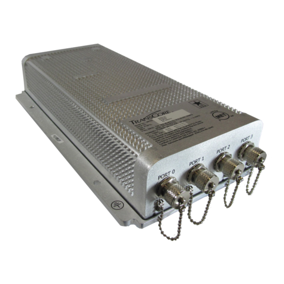
TransCore Multiprotocol Reader Extreme Manuals
Manuals and User Guides for TransCore Multiprotocol Reader Extreme. We have
1
TransCore Multiprotocol Reader Extreme manual available for free PDF download: System Manual
TransCore Multiprotocol Reader Extreme System Manual (208 pages)
Brand:
TransCore
| Category:
Rfid Systems
| Size: 4 MB
Table of Contents
Table of Contents
12
Chapter 1 Introduction
19
Table 1 - 1 MPRX System Guide Overview
20
Table 1 - 2 Typographical Conventions
21
Licensing Requirements
22
Technical Support
22
Chapter 2 Developing the Site Plan
25
System Description
25
Figure 2 - 1 MPRX End Views
25
Overview of Site Planning
26
Reading of Mixed Population Tags
26
Antenna and Tag Alignment
27
Figure 2 - 2 Tag and Antenna Orientation (Horizontal Polarization)
27
Figure 2 - 3 Horizontally Polarized Tag
28
Antenna Selection
29
Site Layout and Traffic Flow
29
Figure 2 - 4 Antenna Location Relative to Tag Position
29
Electrical and Communications Requirements
32
Table 2 - 3 Connector Cabling Accessory Kits
33
Table 2 - 4 Power Supply Current Requirements
33
Figure 2 - 5 Location of Host Port on MPRX
34
Figure 2 - 6 Pin Assignments for Host Connector
34
Figure 2 - 7 Location of Sense Port on MPRX
35
Figure 2 - 8 Pin Assignments for Sense Connector
35
Table 2 - 5 Reader to Antenna Cable Performance
36
Chapter 3 Choosing, Installing, Removing Tags
38
Compatible Tag Types
38
Recommended Mounting Locations
38
Table 3 - 1 Tags Read by the MPRX
38
Figure 3 - 9 Clear Zone -Side View
40
Figure 3 - 10 Clear Zone -End View
40
Figure 3 - 11 Mounting Location Examples
41
Locomotive Mounting Guidelines
42
Figure 3 - 1 2 Tag Placement Window for Locomotives - Right Front
42
Figure 3 - 13 Right Front Placement of Tag on Locomotive
43
Figure 3 - 1 4 Tag Placement Window Location for Locomotives - Left Rear
43
Rail Car Mounting Guidelines
44
Figure 3 - 15 Optimal Tag Placement for Locomotives
44
Figure 3 - 16 Tag Placement Window Location for Rail Cars -"A" Right Side
45
Figure 3 - 1 7 Tag Placement Window Location for Rail Cars -"B" Left Side
45
Tank Car Mounting Guidelines
46
Figure 3 - 18 Optimal Tag Placement for Rail Cars
46
Figure 3 - 19 Tag Placement Window Location for Tank Cars -"B" Left Side
47
Figure 3 - 20 Optimal Tag Placement for Tank Cars
47
Chapter 4 Installing the MPRX
49
Installation Process
49
Pre-Installation Testing of the MPRX
50
Table 4 - 1 Installation Accessories
50
Figure 4 - 1 Wiring for Audible Circuit Tester
51
Figure 4 - 2 Connect RF N-Type Load or Attenuator to Reader Cable End
52
Figure 4 - 3 Short Load to Earth Ground
52
Figure 4 - 4 MPRX Showing Antenna Ports
53
Figure 4 - 5 Location of MPRX Ground Stud
54
Figure 4 - 6 Location of Communications/Power Port on MPRX
55
Table 4 - 2 MPRX-To-Host Communications Cable Pin Designations
55
Mounting the MPRX
56
Figure 4 - 7 MPRX Outer Dimensions and Mounting Hole Locations (Not to Scale)
57
Mounting the Antenna Rail-Side
58
Connecting the Power Supply
58
Connecting Communications
59
Connecting Sense Input and Sense Output Circuits
59
Marking the Read Zone
60
Table 4 - 3 Commands for Testing RF Port-0
61
Figure 4 - 8 Sample Read Zone Marking Pattern
62
Table 4 - 4 Commands for Testing RF PORT-1
63
Table 4 - 5 Commands for Testing RF PORT-2
63
Table 4 - 6 Commands for Testing RF PORT-3
63
Chapter 5 General Software Information
65
Command Entry Conventions
66
Table 5 - 1 Four-Character Command Structure
66
Command Response Conventions
67
Operating Parameters
67
Table 5 - 2 Sample Command Sequence
67
Power Fail
68
Program Download
68
Startup
68
Tag/Message Buffer
69
Chapter 6 Communications Protocols
72
Introduction
72
Basic Protocol
73
Error Correcting Protocol
73
Data Inquiry Protocol
74
Basic Protocol and ECP Format
74
Host-Addressed Failure Conditions
81
ECP Reliability
82
CRC Calculation
82
Manually Disabling ECP for Maintenance
85
Chapter 7 Commands
88
Introduction
89
Operating Modes
89
Command List
91
Table 7 - 1 Select Baud Rate Commands
93
Table 7 - 2 Select Stop Bits Commands
93
Table 7 - 3 Select Parity Commands
94
Table 7 - 4 Append Time and Date Commands
96
Table 7 - 5 Append Auxiliary Information Commands
97
Table 7 - 6 Unique ID Code Criteria
98
Table 7 - 7 Select Valid Code Commands and Frames
99
Table 7 - 8 Flow Control Commands
112
Table 7 - 9 RF Control Commands
113
Table 7 - 10 RF Attenuation Command Variables
114
Table 7 - 11 Select RF Frequency Commands
116
Table 7 - 12 Presence Without Tag Report Commands
117
Table 7 - 13 RF Control Algorithm Commands
118
Table 7 - 14 Timeout Period Values
119
Table 7 - 15 Input Inversion Options
120
Chapter 8 Configuring the MPRX
127
Configuring the Reader
128
Table 8 - 1 MPRX Default Configuration Settings
128
Configuring Parameters with Terminal Emulation Software
129
Figure 8 - 1 Connection Description Dialog Box
130
Figure 8 - 2 Phone Number Dialog Box
130
Figure 8 - 3 COM 1 Properties Dialog Box
131
Figure 8 - 4 Hyper Terminal Main Screen
132
Figure 8 - 5 Sign-On Message
133
Table 8 - 2 Command Sequence to Verify Communications
134
Figure 8 - 6 Tag and Antenna Orientation (Horizontal Polarization)
135
Figure 8 - 7 Successful Tag Read
136
Figure 8 - 8 Second Successful Tag Read
136
Configuring MPRX Parameters
137
Figure 8 - 9 MPRX RF Control Options
140
Chapter 9 Troubleshooting and Maintenance
146
Error Messages
147
Table 9 - 1 Error Messages
147
Table 9 - 2 Symptoms and Remedies
148
MPRX Repair
150
Technical Support
150
Marketing Support
151
Chapter 10 Interface to Train Recording Unit
153
TRU System Overview
154
Figure 10 - 1 TRU Front Panel Showing Operational Leds
154
MPRX to TRU Connection
155
Figure 10 - 2 TRU-MPRX Communications Interface Cable Port (Bottom of TRU)
155
Figure 10 - 3 MPRX-TRU Communications Interface Cable
156
Table 10 - 1 MPRX-To-TRU Interface Cable Pin and Signal Designations
157
Chapter 11 AT5720 Check Tag-To-MPRX Assembly
159
Required Supplies
159
Table 11 - 1 Check Tag Kit Parts List
159
Figure 11 - 1 Place Nut and Grommet over Exposed Check Tag Wires
160
Figure 11 - 2 Feed Check Tag Wires through Plastic Housing Connector
160
Figure 11 - 3 Connect Check Tag Wires
160
Figure 11 - 4 Two Check Tag Assemblies Connected to Terminal Strip
161
Table 11 - 2 Check Tag 0 Wire Assignments
161
Table 11 - 3 Check Tag 1 Wire Assignments
161
Figure 11 - 5 Securing Terminal Strip into Connector Housing
162
Figure 11 - 6 Plastic Nuts with Grommets
162
Figure 11 - 7 Nylon Cap Securely Fastened in Unused Port
163
Figure 11 - 8 Check Tag Assembly Secured to MPRX Port
163
Appendix A Glossary
165
Appendix B Technical Specifications
172
Reader Specifications
173
Appendix C Wiring Information
176
Table C - 1 Communications Interfaces and Conductor Requirements
176
Table C - 2 MPRX Host Communications Cable Pin Designations
177
Table C - 3 MPRX SENSE Communications Cable Pin Designations
178
Appendix D Command Quick Reference
179
Command Syntax
180
Factory Default Settings
180
Table D - 1 MPRX Default Configuration Settings
180
Numerical Command List
181
Table D - 2 MPRX Commands Listed Numerically
182
Alphabetical Command List
192
Table D - 3 MPRX Commands Listed Alphabetically
192
Appendix E Compatible Tag Information
204
Tag Configurations
205
Table E - 1 Sego Protocol Tags
205
Table E - 2 AAR-Formatted Tags
206
Tag Data Formats
207
Advertisement
Advertisement
Related Products
TransCore MPRX Series
TransCore MPRX 10-7200-001
TransCore MPRX 10-7210-001
TransCore MPRX 10-7200-002
TransCore MPRX 10-7210-002
TransCore MPRX
TransCore Amtech IT2200
TransCore Encompass 1150
TransCore encompass4
TransCore Categories
Card Reader
Rfid Systems
Marine Radio
Motherboard
Barcode Reader
More TransCore Manuals
Login
Sign In
OR
Sign in with Facebook
Sign in with Google
Upload manual
Upload from disk
Upload from URL