Table of Contents
Advertisement
TransCore's Multiprotocol Reader Extreme (MPRX) is a radio frequency identification
(RFID) reader designed for harsh environment applications. This guide provides site
planning, testing, and operating instructions for this system.
This guide is intended for use by authorized TransCore dealers, installers, and
service personnel. The MPRX is a contained unit. Once the system is set up and
tested by the authorized installer, no additional service is required.
MPRX Reader
User Guide
16-0079-001 Rev D 2/2020
Trusted Transportation Solutions
Advertisement
Table of Contents

Related Manuals for TransCore MPRX Series


Summary of Contents for TransCore MPRX Series
- Page 1 (RFID) reader designed for harsh environment applications. This guide provides site planning, testing, and operating instructions for this system. This guide is intended for use by authorized TransCore dealers, installers, and service personnel. The MPRX is a contained unit. Once the system is set up and tested by the authorized installer, no additional service is required.
- Page 2 Information in this document is subject to change and does not represent a commitment on the part of TransCore, LP. © 2016-2020 TransCore, LP. All rights reserved. TRANSCORE, AMTECH, EGO, and ENCOMPASS are registered trademarks and are used under license. All other trademarks are the property of their respective owners.
- Page 3 Unauthorized modification may void the equipment authorization from the FCC and will void the warranty. USE OF SHIELDED CABLES AND GROUNDING 47 CFR §15.27(A) NOTE: Shielded cables and earth grounding the unit is recommended for this equipment to comply with FCC regulations. TRANSCORE, LP TransCore Proprietary...
- Page 4 UTILISATION DE CÂBLES BLINDÉS ET MISE À LA TERRE 47 CFR §15.27(A) REMARQUE : Il est recommandé d’utiliser des câbles blindés et une mise à la terre avec cet appareil afin de répondre aux réglementations de la FCC TRANSCORE, LP ÉTATS-UNIS TransCore Proprietary...
- Page 5 L'exploitation est autorisée aux deux conditions suivantes: l'appareil ne doit pas produire de brouillage, et 2 ) l'utilisateur de l'appareil doit accepter tout brouillage radioélectrique subi, même si le brouillage est susceptible d'en compromettre le fonctionnement. TransCore Proprietary...
- Page 6 Occupational (Controlled) and General Population/Public (Uncontrolled), the recommended levels for each of the agencies are presented in the next sections with TransCore’s recommendations for safety in the last section. OSHA (Occupational Safety and Health Administration) OSHA (an agency of The United States of America) legislates in the Code of Federal Regulations (CFR) Title 29 Part 1910 Subpart G 1910.97 titled “Nonionizing radiation”, a maximum...
- Page 7 The MPE minimum distances are 18 in (45 cm) for the Controlled environment and 47 in (120 cm) for the General Public/Uncontrolled environment. TransCore Recommendation on MPE (Maximum Permissible Exposure) The calculated power densities and MPE distance for each of the agencies respective to the environment is shown below.
- Page 8 (accès contrôlé) ou pour la population générale/le grand public (accès non contrôlé), TransCore présente les niveaux recommandés par chaque organisme dans ses recommandations sécuritaires détaillées dans la dernière section.
- Page 9 45 cm (18 po) pour l’environnement professionnel/contrôlé et de 120 cm (47 po) pour le grand public/environnement non contrôlé. Recommandations de TransCore sur les limites d’exposition maximale autorisée (normes MPE) Les densités de puissance et la distance MPE calculées par chaque organisme pour un environnement donné...
- Page 10 2 ) Le personnel d’entretien (c’est-à-dire dans un environnement professionnel/contrôlé) doit rester à au moins 45 cm (18 po) de l’antenne et limiter son temps d’exposition à 6 minutes lorsque l’appareil est en fonctionnement. TransCore Proprietary...
- Page 11 (AAR-formatted operation) frequency band is 902.25 to 903.75 MHz and 910.00 to 921.50 MHz. The user is responsible for filing the FCC license according to FCC regulations, but the TransCore dealer will provide assistance and support as necessary to complete these forms. Forms are available online at the FCC internet site http://wireless.fcc.gov/uls.
-
Page 12: Table Of Contents
MPRX User Guide Table of Contents Licensing Requirements ........... xi Chapter 1 ... - Page 13 Chapter 6 Configuration ......6–86 Configuring the Reader ..........6–86 Terminal Emulation Software .
- Page 14 MPRX User Guide List of Figures Figure 1 MPRX End Views ........1–18 Figure 2 MPRX Communication Ports .
- Page 15 List of Tables Table 1 Connector Cabling Accessory Kits ......1–18 Table 2 Power Supply Current Requirements ......1–19 Table 3 Recommended Cables .
- Page 16 MPRX User Guide Table 25 Input Inversion Options ........5–80 Table 26 ...
-
Page 17: Chapter 1 System Overview
The MPRX is a reader that supports Association of American Railroads (AAR) formatted tags and TransCore’s high-performance Super eGo® (SeGo) radio frequency identification (RFID) technology. The MPRX is a high-power unit that reads both full frame and half frame tags. The reader output power can be adjusted using reader commands. -
Page 18: Reader
MPRX host cable assembly 5m (200in) 58-7200-004 MPRX host cable assembly 10m (400in) 58-7201-001 MPRX sense connector leads 0.15m (6in) 58-7201-002 MPRX sense cable assembly 3m (120in) 58-7201-003 MPRX sense cable assembly 5m (200in) 58-7201-004 MPRX sense cable assembly 10m (400in) 1–18 TransCore Proprietary... -
Page 19: Figure 2 Mprx Communication Ports
Table 2 Power Supply Current Requirements Input Voltage (VDC) Power (W) 28.7 27.4 Host Communications The MPRX communicates through an asynchronous RS–232, RS–422, or Ethernet interface. Figure 2 shows the MPRX communications ports. Figure 3 shows the host connector pin designations. Figure 2 MPRX Communication Ports TransCore Proprietary 1–19... -
Page 20: Figure 3 Pin Designations For Host Connector
Pin Number Operation RS232_TX RS232_RX LOCK (No Connect on wayside MPRX)* LOCK_RTN RS422_TX+ RS422_TX– RS422_RX+ RS422_RX– COM_GND (RS232 GND) COM_GND (RS422 GND) +V In +V Return * +5V on Wayside MPRX. Figure 3 Pin Designations for Host Connector 1–20 TransCore Proprietary... -
Page 21: Figure 4 Socket Designations For Sense Connector
5V supply. When Tag Lock is enabled, internal relay connects LOCK_RTN to LOCK(5V). The output circuit is not intended for the direct control of electromechanical devices such as motorized barrier arms. For such applications, the MPRX output circuit should be used to drive a secondary, appropriately rated high-power relay. TransCore Proprietary 1–21... -
Page 22: Compatible Tag Types
Compatible Tag Types The MPRX provides the capability to read Association of American Railroads (AAR), American Trucking Associations (ATA), and Intergency Agency Group (IAG) formatted tags, as well as TransCore Super eGo (SeGo) protocol tags. Refer to “Appendix E Compatible Tag Information” on page E–134 for information about the numerous tag models. -
Page 23: Chapter 2 Test Procedures
At least one MPRX-compatible antenna • Antenna RF cable These may be ordered as accessories from TransCore or obtained from other sources. Additional Materials Needed for Testing You will need these additional materials to perform the pretests on the MPRX: •... -
Page 24: Table 4 Pretest Accessory Options
MPRX User Guide Pretest Accessory Options Available From TransCore Table 4 lists optional TransCore MPRX installation accessory items. Table 4 Pretest Accessory Options Part No. Description 58-7200-001 MPRX Host Connector with Leads 0.15m (6in) 58-7200-002 MPRX Host Cable 3m (120in) 58-7200-003 MPRX Host Cable 5m (200in) -
Page 25: Pre-Installation Testing Of The Mprx
When you touch the leads together, the box will produce an audible sound. Pin 3 on Host Connector Pin 4 on Host Connector 9VDC 6-12VDC Battery Buzzer Figure 6 Wiring for Audible Circuit Tester for Onboard MPRX TransCore Proprietary 2–25... -
Page 26: Connecting The Antenna(S)
Required Equipment This procedure requires the following equipment. • MPRX • External antenna • Grounding RF cable (long enough to reach Earth Ground source) • N-type load (e.g., 50 Ω) or RF attenuator (e.g., 20 dB) 2–26 TransCore Proprietary... -
Page 27: Figure 8 Connect Rf N-Type Load Or Attenuator To Reader Cable End
Earth Ground. CAUTION TransCore does not recommend using a screwdriver or other tool to short the RF cable center conductor to the outer ground of the cable. This grounding method can damage the center pin or the threads of the connector. -
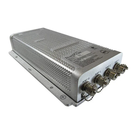
Page 28: Figure 10 Mprx Showing Antenna Ports
4. The ports can be turned on in consecutive order. If all four ports will not be used, start with Port 0 and turn on connected ports. Unused ports should be set to OFF. Refer to “Appendix D Encompass 6 Options” on page D–382 for a list of commands. Figure 10 MPRX Showing Antenna Ports 2–28 TransCore Proprietary... -
Page 29: Connecting The Power Supply
To avoid damage to the MPRX, first connect the reader to Earth Ground using a ground cable and stake before powering up the reader or connecting to an antenna. TransCore recommends following the National Electric Code or equivalent code for surge protection for the locale where the MPRX is installed. -
Page 30: Figure 12 Location Of Host/Sense Ports On Mprx
Sense connector. Figure 12 Location of Host/Sense Ports on MPRX Table 6 Pin Assignments for Host Connector Pin Number Operation RS232_TX RS232_RX LOCK LOCK_RTN RS422_TX+ RS422_TX– RS422_RX+ RS422_RX– COM_GND (RS232 GND) COM_GND (RS422 GND) +V In +V Return 2–30 TransCore Proprietary... -
Page 31: Table 7 Socket Assignments For Sense Connector
Table 8 Inrush and Steady State Currents for MPRX MPRX Current Steady State Voltage (VDC) Inrush Current (A) Inrush Time (ms) Current (A) 4.89 1.38 1.68 2.46 0.87 18.9 2.46 0.44 29.12 0.30 37.91 0.23 40.11 0.20 TransCore Proprietary 2–31... -
Page 32: Connecting Communications
The relay contact is rated at 42.2 VAC peak (30 Vrms) or 60 VDC at 1 A maximum. CAUTION If controlling an external gate or device requiring high current, an isolation transformer is required. 2–32 TransCore Proprietary... -
Page 33: Table 9 Antenna Mux Channel Identification
To interface through the Ethernet port of the MPRX, connect via the M12 Ethernet port (Use an M12 to RJ45 adapter if required). A static IP address will need to be assigned to the local host if directly connected, or the reader may be attached to the network. TransCore Proprietary 2–33... -
Page 34: Figure 13 Stand-Alone Deviceinstaller Link
Connecting Directly to Computer Ethernet Port Go to the computer’s network setting and change the IP address and Subnet mask of the network interface controller (NIC) card you are connecting to as shown in Figure 15. Figure 15 Connecting Directly to Computer Ethernet Port 2–34 TransCore Proprietary... -
Page 35: Figure 16 Multiple Nic Cards
For the direct-connect to the computer’s Ethernet port option, choose the network adapter with the 169.254.10.1 address. To connect to the corporate network, choose the Local Area Connection. 4. The next screen prompts for an update (Figure 18). Select NO. Figure 18 Check for Updates Screen TransCore Proprietary 2–35... -
Page 36: Figure 19 Disable Firewall
Finding the IP Address of the Reader Note: If a firewall is present it will need to be disabled to allow access (Figure 19). Figure 19 Disable Firewall From the Lantronix DeviceInstaller, right-click on the appropriate connection and select refresh (Figure 20). Figure 20 LanTronix DeviceInstaller Screen 2–36 TransCore Proprietary... -
Page 37: Figure 21 Xport Direct+ Device Screen
2. The Xport Direct+ device will populate on the right side of the window (Figure 21). Use the IP address to configure your terminal emulator connection. Use Telnet and Port 10001. Figure 21 Xport Direct+ Device Screen 3. The opened connection works just like a serial connection. TransCore Proprietary 2–37... -
Page 38: Chapter 3 General Software Information
This example assumes that an MPRX with serial number SN97001P running version X.XX software is connected to a PC running a terminal emulation software package. The command sequence verifies that communications are working correctly. 3–38 TransCore Proprietary... -
Page 39: Table 11 Sample Command Sequence
Program Download stores the MPRX application software into the reader’s flash memory. It is used to install program upgrades, add features, and to recover from corrupted program data. Note: Program Download is a custom TransCore utility host process. TransCore Proprietary... -
Page 40: Startup
Download Procedures If TransCore releases a new version of the MPRX software or if the MPRX does not appear to be working properly, you may need to download the software to the MPRX. Contact technical support or your TransCore sales representative. - Page 41 MPRX is operating out of boot ROM. In this case, the MPRX automatically enters download mode and waits for a new program to be loaded into the flash memory. Contact TransCore Technical Support for assistance. Tag/Message Buffer The MPRX maintains a tag buffer in battery backed RAM to save tag IDs acquired when data inquiry protocol is used.
-
Page 42: Chapter 4 Communications Protocols
MPRX as the XOFF character, which would suspend reader output without information reaching the host device. For more information, refer to “Reader Transmissions” on page 4–44. Note: TransCore recommends that XON/XOFF flow control be disabled while using ECP. 4–42 TransCore Proprietary... -
Page 43: Basic Protocol
When the quality of data communications is imperative or may be suspect, you can utilize ECP to ensure the integrity of data transmitted between the MPRX and the host. Note: TransCore recommends that basic protocol (not ECP) be used when commands are entered manually at the keyboard. -
Page 44: Data Inquiry Protocol
#Error08, or #Error11 message; or a sign-on message. Auxiliary data may also be included. Field containing four ASCII digits that represent the 16-bit CRC value calculated on the <crc> message. The CRC value is calculated on bytes between the <som> character and the first <crc> byte. 4–44 TransCore Proprietary... - Page 45 When the MPRX receives an ACK message, the system software treats the message as having been properly received by the host. The software increments the sequence number, and advances pointers to the next message in the MPRX’s message queue to prepare for sending the next message. TransCore Proprietary 4–45...
- Page 46 If the sequence number is not updated before transmission of the next command, the MPRX will not service the new command; it will retransmit its previous message. A command/message sequence is not complete until the host updates its sequence number. 4–46 TransCore Proprietary...
- Page 47 Sample Messages This section contains examples of typical messages transmitted between the MPRX and the host device. Reader Transmissions Basic protocol reader transmission #KING 1302<eom> Host response No host response for non-ECP ECP reader transmission #4KING 1302 <crc><eom> TransCore Proprietary 4–47...
- Page 48 Select RF Operating Frequency command where 647XXX is the command and XXX is 647XXX a hexadecimal value from 000 to 118. In this example, XXX sets the RF frequency to 903 MHz. CRC value for the message <crc> End-of-message character <eom> Command has been invoked by the MPRX #Done 4–48 TransCore Proprietary...
- Page 49 The host device can remotely set the MPRX’s communications parameters while in the command mode, but TransCore does not recommend this action if communications conditions are marginal. After the MPRX receives new communications parameters, the MPRX issues the #Done message and switches to the new configuration immediately.
- Page 50 If the MPRX transmits an asynchronous message and the host does not send an ACK before the ECP timeout occurs, the MPRX retransmits the message. Receive Timeout If the MPRX receives a <som> but does not receive a matching <eom> before the ECP timeout occurs, it discards the incomplete message and resets its receiver. 4–50 TransCore Proprietary...
-
Page 51: Ecp Reliability
The CRC used by the ECP is based on a 16-bit algorithm. The algorithm, as implemented, operates on eight-bit characters, for example, a seven-bit ASCII character plus one optional parity bit. The 16-bit result is converted to four ASCII hex characters and is appended to messages transmitted by the MPRX. TransCore Proprietary 4–51... - Page 52 (--counter >= 0) if (temp & 0x8000) temp <<= 1; temp += (((ch <<= 1) & 0x0100) != 0); temp ^= 0x1021; else { temp <<= 1; temp += (((ch <<= 1) & 0x0100) != 0); return(temp); 4–52 TransCore Proprietary...
- Page 53 0x7a16, 0x0af1, 0x1ad0, 0x2ab3, 0x3a92, 0xfd2e, 0xed0f, 0xdd6c, 0xcd4d, 0xbdaa, 0xad8b, 0x9de8, 0x8dc9, 0x7c26, 0x6c07, 0x5c64, 0x4c45, 0x3ca2, 0x2c83, 0x1ce0, 0x0cc1, 0xef1f, 0xff3e, 0xcf5d, 0xdf7c, 0xaf9b, 0xbfba, 0x8fd9, 0x9ff8, 0x6e17, 0x7e36, 0x4e55, 0x5e74, 0x2e93, 0x3eb2, 0x0ed1, 0x1ef0, TransCore Proprietary 4–53...
-
Page 54: Manually Disabling Ecp For Maintenance
ECP loop. This command sequence uses four ASCII < ` > characters (60 hex) as wild card CRC values. Note: The ASCII <`> character (60 hex) is commonly located on the ~ key. 4–54 TransCore Proprietary... - Page 55 Reader transmission on power-up: #0 Model …. SN <crc><eom> Manually enter: #0@````<eom> Reader response: #2 Copyright 2008 TransCore <crc><eom> Manually enter: #2@````<eom> Manually enter: #101‘‘‘‘<eom> This puts reader into command mode Reader response: #1Done<crc><eom>...
-
Page 56: Chapter 5 Commands
0 on check tag pin 1. #8152 sets the check tag address to 1 on check tag pin 1. #8153 Note: The MPRX transmits ID codes to the host device when the MPRX is in data mode. 5–56 TransCore Proprietary... - Page 57 While in download mode, the MPRX turns RF off, does not process tags, and does not echo host commands. Typically, TransCore trained personnel download new application code using a custom firmware loader program. Contact TransCore Technical Support for information about firmware updates and procedures TransCore Proprietary 5–57...
-
Page 58: Command List
Reader response: #Done Switch on RF port 3, Fire Off Check Tag Address 1 on Check Tag pin 1 #8113 Reader response: #Done Set Check Tag Address to 0 on Check Tag pin 0. #8150 Reader response: #Done 5–58 TransCore Proprietary... -
Page 59: Table 12 Select Baud Rate Commands
If ECP is enabled, ensure that the ECP timeout is sufficient for the new baud rate. 101N Select Stop Bits selects the number of stop bits for reader character transmission. The factory default #101N setting is 1 stop bit. The N variable specifies the number of stop bits as indicated in Table 13. TransCore Proprietary 5–59... -
Page 60: Table 13 Select Stop Bits Commands
(00 to 59). represents seconds (00 to 59). represents hundredths of a second (00 to 99). is the time delimiter. If hundredths of a second is not specified, the reader sets the hundredths register to 00. Reader response: #Done 5–60 TransCore Proprietary... - Page 61 (Command #302). The reader returns an #Error message if its tag buffer contains data. The reset reader Command #63 may be transmitted to clear the buffer; however, tag ID data will not be TransCore Proprietary 5–61...
-
Page 62: Table 15 Append Time And Date Commands
ID. Value can be set with Command #60NN. auxiliary information delimiter antenna number. number of reads (00 to FF hexadecimal) of the previous tag on this antenna 5–62 TransCore Proprietary... -
Page 63: Table 17 Unique Id Code Criteria
When the uniqueness filter is set to separation of one ID, the newly acquired ID is transmitted only if it is different from the first item. Separation of two IDs allows transmission if the new ID is different from Items 1 and 2 in the comparison register. TransCore Proprietary 5–63... -
Page 64: Table 18 Select Valid Code Commands And Frames
Places a time limit on the uniqueness criterion set by Select Unique ID Code Criteria (#410N). The parameter N sets the number of minutes on the timeout clock. The factory setting is two minutes (N = 1). Command Timeout Clock 2 minutes (factory setting) #441 15 seconds #442 5–64 TransCore Proprietary... - Page 65 Super eGo ® (SeGo) protocol tag initialize command #456 as part of the multi-tag sort function. When the reader sends the SeGo protocol tag initialize command, all tags in the RF field reenter the sort process. Reader response: #Done TransCore Proprietary 5–65...
- Page 66 #505 number. Reader response: Model E4 Series Ver X.XX SNSSSSSS where Version number X.XX Serial number of the unit, skipping the fourth character printed on the reader product SSSSSS label 5–66 TransCore Proprietary...
- Page 67 MAIN B<2 to 7> S<0 to 1> P<0 to 2> D0 where 1200 baud 2400 baud 4800 baud 9600 baud (factory default) 19.2 kbps 38.4 kbps one stop bit (factory default) two stop bits no parity (factory default) even parity TransCore Proprietary 5–67...
- Page 68 Reader response: ECPS P<0 to 2> T<01 to FF> X<0 to 2> S0 where Basic protocol selected (factory default) ECP enabled data inquiry protocol enabled ECP timeout where xx = 01 to FE (hexadecimal) | Timeout (ms) = 50 * xx If xx = FF timeout disabled 5–68 TransCore Proprietary...
- Page 69 RF power attenuation, where 00 is maximum output power and 0A is minimum output power (10dB less than maximum power). Fixed For example, if factory default settings are assigned, the reader message is RFST C1 O0 T1 Fxxx R1F G1F A00 I04 TransCore Proprietary 5–69...
- Page 70 RF off on timeout or presence condition false (factory default) RF timeout of 0 ms (always expired) 4 ms 8 ms 12 ms 20 ms 24 ms 32 ms 48 ms 60 ms 92 ms 152 ms 300 ms 452 ms 600 ms 5–70 TransCore Proprietary...
- Page 71 ISO standards. Refer to “452 Disable Tag Translation Mode (Factory Default)” on page 5–65 “453 Enable Tag Translation Mode” on page 5–65 for more information. Reader response: TT <0 to 1> where tag translation mode disabled tag translation mode enabled TransCore Proprietary 5–71...
- Page 72 User-Programmable GSE configuration command. 552 Display Antenna Multiplexing Mode displays the antenna multiplexing mode When the MPRX mode is enabled #552 Reader response: MUX x<0 to 3> <MPRX> where antenna multiplexing disabled, RF on port 0 only 5–72 TransCore Proprietary...
- Page 73 When in MPRX mode and/or if antenna multiplexing #577 is enabled, the response is Reader response: HDSH C0 <ww> C1 <xx> C2 <yy> C3 <zz> where count from port 0 count from port 1 TransCore Proprietary 5–73...
- Page 74 Uppercase or lowercase characters are allowed for NN; for example, hex digits A through F or a through f. The value for NN specifies the timeout interval as follows: ms 50 * NN for NN = 01 to FE (1–254) where Factory default (12,700 ms or 12.7 seconds) 5–74 TransCore Proprietary...
-
Page 75: Table 19 Software Flow Control Commands
XOFF character (host software Command 13H). It does not resume transmitting until it receives an XON character (host software Command 11H). Note: TransCore recommends that XON/XOFF Software Flow Control be disabled while using the ECP. 6170 Disable Echo Mode disables the reader’s echo of received host commands. -
Page 76: Table 20 Rf Control Commands
Note: This command does not reset any other configuration parameters. Reader response: Model E4 Series Ver X.XX SNSSSSSS Copyright 2008 TransCore where Version number X.XXD... -
Page 77: Table 21 Rf Attenuation Command Variables
#Error06 message to the host. Until the frequency is reset using command the unit displays the same error message each time it is powered up or if an attempt is #647XXX made to enable the RF by host or by external sensor. TransCore Proprietary 5–77... -
Page 78: Table 22 Presence Without Tag Report Commands
Enable presence without tag reports 6901 Note: These commands only have an effect when the reader is not in MPRX mode. Reader response: #Done Refer to “Basic Protocol and ECP Format” on page 4–44 for message format information. 5–78 TransCore Proprietary... -
Page 79: Table 23 Rf Control Algorithm Commands
Uppercase or lowercase characters are allowed for N; for example, hex digits A through F or a through f. The commands and corresponding timeouts are shown in Table 24. Table 24 Timeout Period Values Command Timeout (ms) 0 (always expired) 6930 6931 6932 6933 6934 6935 6936 6937 TransCore Proprietary 5–79... -
Page 80: Table 25 Input Inversion Options
Table 25 Input Inversion Options Command Option Disable input inversion (factory default) 6940 Enable input inversion 6941 695S...S Set Serial Number (Factory Default) assigns the reader serial number according to the format: #695 695SSSSSS where SSSSSS is the serial number. 5–80 TransCore Proprietary... - Page 81 As an example, to configure a reader to have only tags with data in byte locations 10, 12, and 15 (decimal) with hexadecimal values “00,” “01,” and “02,” the following command is used: #697 A4 0A 0005014202024133 TransCore Proprietary 5–81...
- Page 82 Ctag pin 1 to set the Ctag character. #8143X 8150 Set Check Tag Address to 0 on Check Tag Pin 0 sets the check tag address to 0 on check tag pin 0. #8150 5–82 TransCore Proprietary...
- Page 83 Reader response: #Done 843 Enables the AI1200 Emulation Mode enables the AI1200 Emulation mode. #843 Reader response: #Done 850 MUX RF Port 0 (Factory Default) enables RF port 0, which disables antenna multiplexing. #850 Reader response: #Done TransCore Proprietary 5–83...
- Page 84 RF port 2, send the command on Ctag pin 1, to fire off Ctag address 0. #8112 turn on RF port 3, send the command on Ctag pin 1, to fire off Ctag address 1. #8113 send the command on Ctag pin 1 to set the Ctag character. #8143X 5–84 TransCore Proprietary...
- Page 85 RF port. These test mode commands are qualified by the RF on by sense settings. Use #6401 to disable RF on by sense, if desired. TransCore Proprietary 5–85...
-
Page 86: Chapter 6 Configuration
Disabled Unique ID code criteria Separation of 1 ID 4100 Tag translation mode Disabled SeGo protocol tag initialization Enabled during multi-tag sort Reader ID number 6000 Communications protocol Basic Error correcting protocol (ECP) 12.7 sec 612FE timeout 6–86 TransCore Proprietary... -
Page 87: Terminal Emulation Software
“Connecting the MPRX to the Host Port” on page 2–32 Then, enter the appropriate configuration commands through the terminal emulation software on the host. Refer to “Commands” on page 5–56 for a detailed description of all available configuration commands. TransCore Proprietary 6–87... - Page 88 6–88. Note: When testing the MPRX using a laptop computer, TransCore recommends that you configure laptop communication parameters to match those of the host device to which the MPRX will be connected after testing and configuration are completed.
-
Page 89: Table 27 Command Sequence To Verify Communications
5. Verify the COM port settings for the MPRX following the instructions in “Serial Port Communications” on page 6–95 Repeat the procedures in “Verifying Communications” on page 6–88. If you still cannot verify the MPRX and PC communications, contact TransCore Technical Support. TransCore Proprietary 6–89... -
Page 90: Figure 22 Tag And Antenna Orientation (Horizontal Polarization)
Once communications are verified, enter the following sequence of commands to turn on continuous RF: • • #6401 • • 2. Pass one test tag in front of the active MPRX antenna. If the MPRX reads the tag, the terminal emulation application displays the tag information on the screen. 6–90 TransCore Proprietary... -
Page 91: Configuring Mprx Parameters
To set appended tag data parameters Ensure that the host device is in command mode. 2. Enter Command #311 to append auxiliary information or Command #310 to have no auxiliary information appended (factory default). Press ENTER. TransCore Proprietary 6–91... - Page 92 2. Enter Command #560 to display input status change report options and press ENTER. input status change reports disabled (factory default) input status change reports enabled reporting disabled (factory default) changes on input 0 reported changes on input 1 reported changes on either input reported 6–92 TransCore Proprietary...
- Page 93 0.25 MHz steps. You can set the frequency by using a terminal emulation program and issuing the frequency command, as discussed in section “647XXX Select RF Operating Frequency” on page 5–77. Note: For backward compatibility to existing controllers, you can set the RF operating frequency in 500-kHz steps using Command #642NN. TransCore Proprietary 6–93...
-
Page 94: Figure 23 Mprx Rf Control Options
3. To verify that the RF has been changed to the proper setting, type in Command #527 to see the current frequency setting. Caution Contact TransCore if your application requires a frequency outside of the authorized frequency range. RF Transmission The RF transmission can be controlled by connecting a presence detector to the SENSE 0 circuit. - Page 95 Software flow control (XON/XOFF) You can change these parameters in data mode and command mode operation by issuing commands with the host device. Use the following procedures to set serial port communications parameters using the terminal emulation program. TransCore Proprietary 6–95...
- Page 96 (host software command 11H) from the host. If software flow control is not needed, the reader should be configured for no flow control (#6140 Disable Flow Control). Note: TransCore recommends that XON/XOFF software flow control be disabled while using the ECP.
- Page 97 2 watts at 0 dB attenuation to a minimum power level of 200 milliwatts at 10 dB attenuation. Increasing the attenuation lowers the output RF power. 4. Switch to data mode by entering Command #00 and pressing ENTER. TransCore Proprietary 6–97...
- Page 98 Continue increasing the NN value until the read zone matches the desired read zone. When the desired read zone is established, test the read zone with simulated and real traffic by performing the following procedures. 6–98 TransCore Proprietary...
- Page 99 4. If both tags are read, you have successfully adjusted the read range. If one or both tags did not read, follow the suggestions in “Verifying Tag Read Capability” on page 6–90. TransCore Proprietary 6–99...
-
Page 100: Chapter 7 Troubleshooting And Maintenance
You may want to track this error message if it should occur again. If the reader indicates repeated #ErrorRF2 warning messages then return the reader to the factory. 7–100 TransCore Proprietary... -
Page 101: Table 29 Symptoms And Remedies
Troubleshooting If you contact TransCore Technical Support, use the symptom number in Table 29 to reference the problem that you are having with the MPRX. Should problems continue, contact TransCore for return and replacement procedures. Table 29 Symptoms and Remedies Symptom Symptom... - Page 102 When connected to a PC The MPRX works. The software is now loaded. SSSSSS is the that is running terminal TransCore-assigned serial number for this MPRX. However, if communications software, SSSSSS = 000000, a serial number has never been assigned.
-
Page 103: Mprx Repair
Tuning and Verifying the Read Zone” on page 6–97. b Use this number to reference the problem you are having with the MPRX if you contact Transcore for Technical Support. MPRX Repair The MPRX is designed for whole-unit replacement and is manufactured with surface-mounted components. -
Page 104: Chapter 8 At5720 Check Tag-To-Mprx
MPRX User Guide Chapter 8 AT5720 Check Tag-to-MPRX Required Supplies Check Tag Kit (TransCore P/N 19114-00 Before assembling the check tag antenna kit, make sure you have the necessary supplies and tools for this task. You need the following additional materials and/or tools to complete the installation. -
Page 105: Table 31 Check Tag 1 Wire Assignments
Chapter 8 AT5720 Check Tag-to-MPRX Table 31 Check Tag 1 Wire Assignments Pin Number Operation +12VDC OUT I/O GROUND PULSE OUT CTAG 0 Data CTAG 1 Data I/O GROUND TransCore Proprietary 8–105... -
Page 106: Appendix A Glossary
A binary character; for example, one 8-bit ASCII character check tag Tag mounted inside a reader assembly, inside or in close proximity to an external antenna that is used to check operation of the reader Command A–106 TransCore Proprietary... - Page 107 Error correcting protocol ECPS Error correcting protocol status eGo® Proprietary name for ANSI NCITS 256-2001 and ISO 18000-6B compliant TransCore products. A registered trademark of TC License, Ltd. End of line End of message EPROM Erasable programmable read-only memory field Physical area/space in which a tag can be read by the reader;...
- Page 108 Negative acknowledgment (data not valid) passback Used to refer to a tag ID that is not passed on to the tag buffer Personal computer PCKS EPROM flash checksum protocol Specified convention for the format of data messages communicated between devices A–108 TransCore Proprietary...
- Page 109 Status of check tag status SeGo Super eGo (SeGo) is a superset of the eGo protocol Serial number Start of message SSTC Input status change reporting options Small self-contained device acting as an identifying transponder Tag translation TransCore Proprietary A–109...
- Page 110 X/ON and X/OFF are signals to turn a transmitter on or off. The actual signal for X/ON is the same bit configuration as the ASCII Ctrl-Q keyboard combination (11 hexadecimal). The X/OFF signal is the Ctrl-S character (13 hexadecimal). A–110 TransCore Proprietary...
-
Page 111: Appendix B Technical Specifications
Case Aluminum (Allodyne) Power Requirements 12 to 24VDC (Wayside Option) Input Voltage 24 to 110VDC (Onboard Option) Physical Attributes Size 13 x 5 x 2.49 in. (33 x 7.62 x 6.32 cm) Weight 5.9 lb (2.6 kg) TransCore Proprietary B–111... -
Page 112: Figure 25 Mprx Exterior Case Dimensions
AREMA C&S Manual, Part 11.5.1, Class C Operation Shock The MPRX complies with shock tolerance limits Tolerance specified in AREMA C&S Manual, Part 11.5.1, Class C Reader Dimensions Figure 25 illustrates the exterior dimensions of the MPRX case. Figure 25 MPRX Exterior Case Dimensions B–112 TransCore Proprietary... -
Page 113: Figure 26 Mprx End Panel Dimensions With Antenna Ports
MPRX with antenna ports. Figure 26 MPRX End Panel Dimensions with Antenna Ports Figure 27 illustrates the end panel dimensions of the MPRX with communication connectors. Figure 27 MPRX End Panel Dimensions with Communication Connectors TransCore Proprietary B–113... -
Page 114: Appendix C Wiring Information
MPRX User Guide Appendix C Wiring Information Communications Interfaces Table 32 lists the MPRX Host Communications Cable Pin Designations. For TransCore part numbers, refer “Pretest Accessory Options Available From TransCore” on page 2–26. Table 33 lists the interfaces available with the MPRX. Table 32 MPRX Host Communications Cable Pin Designations... -
Page 115: Table 34 Mprx Sense Communications Cable Pin Designations
Chapter C Table 34 lists the MPRX Sense Communications Cable Pin Designations. For TransCore part numbers, refer to “Pretest Accessory Options Available From TransCore” on page 2–26. Table 34 MPRX SENSE Communications Cable Pin Designations SENSE CABLE PAIR COLOR PIN NUMBER NAME black or gray... -
Page 116: Appendix D Command Quick Reference
Separation of 1 ID 4100 Valid ID code criteria Acquisition of 1 ID 4200 Uniqueness time-out 2 minutes Tag translation mode Disabled Multi-tag sort Disabled SeGo protocol tag initialization Enabled during multi-tag sort Reader ID number 6000 D–116 TransCore Proprietary... -
Page 117: Numerical Command List
The following conventions are used in Table 37. Items in bold identify factory default settings. Only the command-related data portion of the reader message is shown. Refer to “Chapter 5 Commands” on page 5–56 for the complete syntax of commands and messages. D–117 TransCore Proprietary... -
Page 118: Table 37 Mprx Commands Listed Numerically
Disable aux info append (default) #Done Enable aux info append #Done Transmit all IDs #Done 4100 Select one ID separation (default) #Done 4101 Select two ID separation #Done 4102 Select three ID separation #Done 4103 Select four ID separation #Done D–118 TransCore Proprietary... - Page 119 #Error if tag protocol is unsupported.. #Done if MPRX model supports this tag protocol Disable SeGo #Error if tag protocol is unsupported #Done if MPRX model supports this tag protocol Enable SeGo #Error if tag protocol is unsupported D–119 TransCore Proprietary...
- Page 120 F> I<0 to 1> RF0S U<0 to 4> V<0 Display RF0 filter status to 3> Display tag translation mode status TT <0 to 1> Display echo status ECHO <0 to 1> Display flash checksum PCKS I0000 Exxxx D–120 D–120 TransCore Proprietary...
- Page 121 612FE Set ECP timeout = 12.7 sec (default) #Done Enable data inquiry protocol #Done 6140 Disable flow control #Done 6141 Enable software flow control (default) #Done 6170 Disable echo mode #Done 6171 Enable echo mode (default) #Done D–121 TransCore Proprietary...
- Page 122 Reset power fail bit #Done Load default operating parameters #Done Disable presence without tag reports 6900 #Done (default) 6901 Enable presence without tag reports #Done 6920 Turn RF off on timeout #Done 6921 Turn RF off on timeout/tag #Done D–122 TransCore Proprietary...
- Page 123 Set check tag address to 1 on check tag pin 0 #Done 8152 Set check tag address to 0 on check tag pin 1 #Done 8153 Set check tag address to 1 on check tag pin 1 #Done Disable automatic periodic RF status report #Done (default) D–123 TransCore Proprietary...
-
Page 124: Alphabetical Command List
ATA Operating Distance = 6431F #Done Maximum (default) #Done if MPRX model supports Disable ATA this tag protocol, #Error if tag protocol is unsupported Disable automatic periodic RF #Done status report (default) Disable aux info append (default) #Done D–124 TransCore Proprietary... - Page 125 Display input status change SSTC E<0 to 1> M<0 to 3> ATA:<E, D> eGo:<I, F, D> Display operating mode status SeGo:<I, F, D> IAG:<E, D> Sort:<E, D> TMM0 Display power fail bit PWRB P<0 to 1> R0 D–125 TransCore Proprietary...
- Page 126 Enable multi-tag sort #Done Enable presence without tag reports 6901 #Done #Done if MPRX model supports Enable SeGo this tag protocol, #Error if tag protocol is unsupported Enable SeGo protocol tag initialization during multi-tag sort #Done (default) D–126 TransCore Proprietary...
- Page 127 TransCore Reset uniqueness #Done RF Attenuation = Full Power 64400 #Done (default) SeGo protocol operating range 6451F #Done distance = Maximum (default) Select 1 valid ID code (default) 4200 #Done Select 2 valid ID codes 4201 #Done D–127 TransCore Proprietary...
- Page 128 Set check tag address to 0 on check 8152 #Done tag pin 1 Set check tag address to 1 on check 8151 #Done tag pin 0 Set check tag address to 1 on check 8153 #Done tag pin 1 D–128 TransCore Proprietary...
- Page 129 1 on check tag pin 0 Switch on RF port 2, fire off check 8112 #Done tag address 0 on check tag pin 1 Switch on RF port 3, fire off check 8113 #Done tag address 1 on check tag pin 1 D–129 TransCore Proprietary...
- Page 130 #Done Turn RF off on timeout 6920 #Done Turn RF off on timeout/no 6922 #Done presence (default) Turn RF off on timeout/tag 6921 #Done Use one stop bit (default) 1010 #Done Use two stop bits 1011 #Done D–130 TransCore Proprietary...
-
Page 131: Table 39 Rf Frequency Commands - Fcc
6470AF 6470C8 910.25 6470C9 910.5 6470CA 910.75 6470CB 6470CC 911.25 6470CD 911.5 6470CE 911.75 6470CF 6470D0 912.25 6470D1 912.5 6470D2 912.75 6470D3 6470D4 913.25 6470D5 913.5 6470D6 913.75 6470D7 6470D8 914.25 6470D9 914.5 6470DA 914.75 6470DB 6470DC D–131 TransCore Proprietary... - Page 132 916.5 6470E2 916.75 6470E3 6470E4 917.25 6470E5 917.5 6470E6 917.75 6470E7 6470E8 918.25 6470E9 918.5 6470EA 918.75 6470EB 6470EC 919.25 6470ED 919.5 6470EE 919.75 6470EF 6470F0 920.25 6470F1 920.5 6470F2 920.75 6470F3 6470F4 921.25 6470F5 921.5 6470F6 D–132 TransCore Proprietary...
-
Page 133: Table 40 Rf Frequency Commands Non- Fcc
Frequency 647014 865.25 647015 865.5 647016 865.75 647017 647018 866.25 647019 866.5 64701A 866.75 64701B 64701C 867.25 64701D 867.5 64701E 867.75 64701F 647020 868.25 647021 868.5 647022 868.75 647023 647024 869.25 647025 869.5 647026 869.75 647027 647028 D–133 TransCore Proprietary... -
Page 134: Appendix E Compatible Tag Information
915 MHz frequency; water- AT5549 Rail battery resistant, metal external install Multifrequency, high-temperature 8-year AT5910 Transportation chemical-resistant case, metal battery external install a These fields apply to eATA-programmed tags only. Contact TransCore for information regarding tags programmed with these features. E–134 TransCore Proprietary... -
Page 135: Tag Data Formats
Appendix E Compatible Tag Information Tag Data Formats Tags are programmed at the TransCore factory with the tag model number, date of manufacture, and data format. Contact TransCore for special order entry procedures for the format that applies to your system. -
Page 136: Table 42 Aar-Formatted Tags
Multifrequency, dynamic tag, metal external install AT5707 Transportation 8-yr 915 MHz frequency, dynamic battery tag, metal external install If desired, in place of 40 six-bit ASCII characters, the AT5707 can support up to 34 seven-bit ASCII characters. E–136 TransCore Proprietary... - Page 138 505.856.8007 transcore.com Trusted Transportation Solutions ©2020 TransCore L.P. All rights reserved. TRANSCORE is a registered trademark, and is used under license. All other trademarks listed are the property of their respective owners. Contents subject to change. Printed in the U.S.A.
Need help?
Do you have a question about the MPRX Series and is the answer not in the manual?
Questions and answers