Advertisement
Available languages
Available languages
Quick Links
G e n e r a l i n f o r m a t i o n :
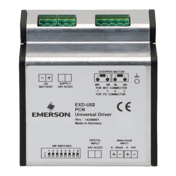
EXD-U02 Universal Driver Module is for driving Emerson stepper motor driven electrical
control valves series EX4-8 and CV4-6. Typical application of EXD-U02 in a CO
transcritical system is shown in Fig. 8.
S a f e t y i n s t r u c t i o n s :
• Read operating instructions thoroughly. Failure to comply can result in device failure,
system damage or personal injury.
• This product is intended for use by qualified personnel having the appropriate
knowledge and skills like trained according to EN 13313.
• Do not exceed the specified maximum ratings for voltage and current.
• Ensure that the system piping is grounded.
• Before installation or service disconnect all voltages from system and device.
• Ensure that design, installation and operation comply with European and national
standards/regulations.
• Do not operate system before all cable connections are completed.
• Do not apply 110/220/230 V to any terminal of driver module.
I n s t a l l a t i o n :
• EXD-U02 delivery is in two versions: as standalone or as kit with K09-U00 electrical
terminal.
• Mount all electrical terminals. Electrical terminal for
analogue signal connection is different to other
terminals in term of size and fit only on location (#6)
as Fig. 3/ 4. The small terminals require smaller size
of screwdriver compared to other terminals.
• EXD-U02 is delivered with bracket suitable for
mounting on DIN-Rail. Hang driver above DIN-Rail
and push down- and backward until it snaps
completely and hold by DIN-Rail.
W i r i n g :
• Entire electrical connections have to comply with local regulations.
• Wiring diagram for single driver with optional backup battery ECP-024 see Fig. 3.
• Single ECP-024 can be connected to two EXD-U02 see Fig. 4
• It is recommended the use of prewired M12 plug and cable assembly (EXV-Mxx) for easy
wiring between EX4-8 or CV4-6 and EXD-U02. The wires colors match to colors coding
of stepper motor terminals (see Fig.3 & 4).
• 24 VAC digital input (#1, Fig. 3 & 4) can be supplied from same source of power. Digital
input act as ON/OFF command and it is only method to make sure valve is fully
closed. The digital input can be controlled by potential free contact(s).
• As illustrated, external contact "C" is a normally open contact, and the
activation/deactivation is in general parallel with compressor ON/OFF. Additional
external contact "P" as normally close in series with contact "C" can be used for pump
down function.
• It is mandatory the external grounding backside of EXD-U02 (Fig. 2).
• Use a class II category transformer (#2) for 24 VAC power supply. Do not ground the
24 VAC line and install proper size of fuse (#3)
• Keep separate the wires for power supply, stepper motor of valve and signal.
• Recommended wire size Ø 0.5...2.5 mm
Special wiring for two valves/drivers from single source of analog input (Fig. 4):
• Two valves operating simultaneously in parallel. It is intended for application that both
valves are synchronized, equally opening or closing. In case of 4...20 mA analog signal,
see Fig.5a (analog inputs burden = 728
(analog input impedance = 12 k
Ω)
D i p s w i t c h e s s e t t i n g ( F i g . 6 ) :
Disconnect power supply as well as analog input signal. Set dip switches by a pencil or
similar according table 1. The dip switches of new EXD-U02 are all set to OFF position
(OFF: Downward / ON: Upward).
1
Valve type/ step
recovery /analog input
EX4-6
OFF
CV4
OFF
CV4.5-6
OFF
OFF
EX7
OFF
EX8
-
Step Recovery – Yes
Step Recovery – No
-
Signal: 4...20 mA
-
-
Signal: 0...10 V
Table 1
Emerson Climate Technologies GmbH
Pascalstrasse 65 I 52076 Aachen I Germany
O P E R A T I N G I N ST RU C T I O N S
Universal Driver Module EXD-U02
for Electrical Control Valves EX4-8 / CV4-6
Fig. 1
Fig. 2
2
.
Ω)
and in case of 0...10 V signal, see Fig. 5b
.
Dip Switch Number
2
3
4
5
6
Dip switch position
OFF
OFF
ON
OFF
OFF
OFF
ON
OFF
OFF
OFF
OFF
ON
ON
OFF
OFF
ON
OFF
OFF
OFF
OFF
ON
ON
OFF
OFF
OFF
-
-
-
-
-
-
-
-
-
-
-
-
-
-
-
-
-
-
-
-
V a l v e S y n c h r o n i z a t i o n :
• The EXD-U02 synchronizes the stepper motor driven valve with the Mechanical
reference point in the fully closed position when the digital input is interrupted for
booster
2
minimum time shown in the Table 2.
S t e p R e c o v e r y f u n c t i o n :
• Step Recovery enables to recover potentially lost steps during operation if the digital
input has not been interrupted for a continuous operation (for more detail see
"Technical Information" of EXD-U02)
WARNING:
• Minimum analog signal (0 VDC in case of 0...10 VDC or 4 mA in case of 4...20 mA)
is not intended for driving valve to fully close position. Only digital input
interruption is the appropriate command for driving valve to fully close position.
S t a r t - u p p r o c e d u r e :
• NOTE: EX/CV valves are delivered in partially open position.
• Vacuum the entire refrigeration circuit. The valve can be driven to close position before
charging the system. In order to close the valve fully, disconnect the Digital input while
keeping the 24 VAC supply voltage connected for a period of time as shown in Table 2.
Valve
EX4-6
EX7
EX8
Table 2
T e c h n i c a l D a t a :
Power supply
NOTE: 24 VDC supply voltage can be used but it results to lower MOPD and it needs to
be verified/approved under system manufacturer responsibility.
Inputs
Outputs
Uninterruptible power
supply ECP-024
Wiring Diagram
(#1)
Digital input terminals/signal (0 V = OFF; 24 V = ON)
(#2)
Transformer
(#3)
Fuse
(#4)
Plug cable assembly EXV-Mxx for connection to EX4-8 / CV4-6
Cable color code:
(#5)
Third party controller's analog signal supplies (4...20 mA or 0...10 V)
(#6)
Analog input terminal/signal (4...20 mA or 0...10 V)
Optional Uninterruptible Power Supply insures the closure of valve during power
(#7)
failure in system.
(#8)
Terminal (EXD-U02 /ECP-024) to be connected to single source. In event of
power interruption, ECP-024 drive automatically the valve(s) to close position.
(C)
Normally open external potential free contact.
Function: Interruption of digital input for synchronization purpose or fully closing
the valve.
(P)
Normally close external potential free contact
(Pump down function)
Compatibility
Dimensions
Marking
7
8
-
-
-
-
-
-
-
-
-
-
OFF
-
ON
-
-
OFF
-
ON
www.climate.emerson.com/en-gb
Valve
Closing time (sec.)
CV4-6
2...5
-
4...5
-
6...8
24 VAC ±10 %, 50-60 Hz
Analog input 4...20 mA, burden 364 Ω,
or
Analog input 0...10 V, impedance 24 kΩ.
Digital input: 24 VAC/DC (+10 %, -15 %), 50-60 Hz
Current outputs for stepper motor of EX4-8/ CV4-6
Required power supply voltage: 24 VAC ±10 %
Outputs: two individual, each +18 VDC
(see Fig. 3, 4, 5a, 5b)
WH=White
BK=Black
BL= Blue
BN=Brown
A1 - Fluid group II
See Fig. 7
(acc. EMC, EN 61326-1, EN 50081, EN 50082.)
OI_EXD-U02_EN_DE_FR_ES_IT_RU_Rev04_866919.docx
EN
Closing time (sec.)
2...5
-
-
Date: 01.06.2022
Advertisement

Related Manuals for Emerson EXD-U02


Summary of Contents for Emerson EXD-U02
- Page 1 (acc. EMC, EN 61326-1, EN 50081, EN 50082.) Disconnect power supply as well as analog input signal. Set dip switches by a pencil or similar according table 1. The dip switches of new EXD-U02 are all set to OFF position (OFF: Downward / ON: Upward).
- Page 2 Tabelle 2 angegebene Mindestzeit unterbrochen wird. • Die EXD-U02 Lieferung erfolgt in zwei Versionen: als Einzelgerät oder als Bausatz mit F u n k t i o n V e n t i l s y n c h r o n i s a t i o n : elektrischen Klemmen K09-U00.
-
Page 3: Instructions De Service
I n s t a l l a t i o n : Vanne Temps fermeture (s) Vanne Temps fermeture (s) • EXD-U02 peut être fourni en deux versions : seul ou en kit avec le lot de connecteurs électriques K09-U00. EX4-6 2…5 CV4-6 2…5... -
Page 4: Instrucciones De Funcionamiento
El driver EXD-U02 sirve para accionar las válvulas electrónicas de motor paso a paso de entrada digital se interrumpe por un espacio de tiempo mínimo según Tabla 2. las series EX4-8 y CV4-6. La aplicación típica de EXD-U02 en un circuito booster de CO se muestra en la Fig. 8. - Page 5 • Disconnettere l'alimentazione e il segnale di ingresso analogico. Impostare i dip switch con una matita (o simile) come in tabella 1. I dip switch del nuovo EXD-U02 sono tutti in posizione OFF (OFF: Verso il basso / ON: Verso l'alto).
-
Page 6: Руководство По Эксплуатации
Ф у н к ц и я в о с с т а н о в л е н и я ш а г о в : М о н т а ж : • Восстановление шагов позволяет восстановить потенциально потерянные во • EXD-U02 поставляется в двух версиях: отдельно или в комплекте с клеммным время работы шаги, если цифровой вход работал непрерывно не прерывался. терминалом K09-U00 (более... - Page 7 EXD-U02 Fig./ Рис. 3 Fig./ Рис. 4 Fig./ Рис. 5a Fig./ Рис. 5b Emerson Climate Technologies GmbH www.climate.emerson.com/en-gb Date: 01.06.2022 Pascalstrasse 65 I 52076 Aachen I Germany OI_EXD-U02_EN_DE_FR_ES_IT_RU_Rev04_866919.docx...
- Page 8 Valvola recupero calore Valvola di espansione Valvola pressione aspirazione Газовый клапан высокого Клапан для рекуперации Регулятор давления в Байпасный клапан Расширительный клапан давления тепла испарителе Emerson Climate Technologies GmbH www.climate.emerson.com/en-gb Date: 01.06.2022 Pascalstrasse 65 I 52076 Aachen I Germany OI_EXD-U02_EN_DE_FR_ES_IT_RU_Rev04_866919.docx...
Need help?
Do you have a question about the EXD-U02 and is the answer not in the manual?
Questions and answers