RedEarth HoneyBadger Installation Manual
Home battery system – off-grid victron with troppo-4841 lithium batteries
Hide thumbs
Also See for HoneyBadger:
- Installation manual (20 pages) ,
- User manual (19 pages) ,
- User manual (18 pages)

Related Manuals for RedEarth HoneyBadger


Summary of Contents for RedEarth HoneyBadger
-
Page 1: Home Battery System - Off-Grid
HoneyBadger Home Battery System – Off-Grid Victron with Troppo-4841 Lithium Batteries Installation Manual... -
Page 2: Safety
Electrical installations-Safety of battery systems for use with power conversion equipment The HoneyBadger must only be installed by suitably qualified personnel who have read and are familiar with its operation and hazards. The battery provided with this system must be charged only by the Victron inverter and MPPT. -
Page 3: Table Of Contents
Home Battery System – Off-Grid ......................1 Safety............................... 2 HoneyBadger Overview ........................... 4 Dimensions and clearance/positioning information ................5 Internal Components description ......................6 8 steps to complete your HoneyBadger installation: ................11 Step 1. Transporting ........................11 Step 2. Positioning ........................12 Step 3. -
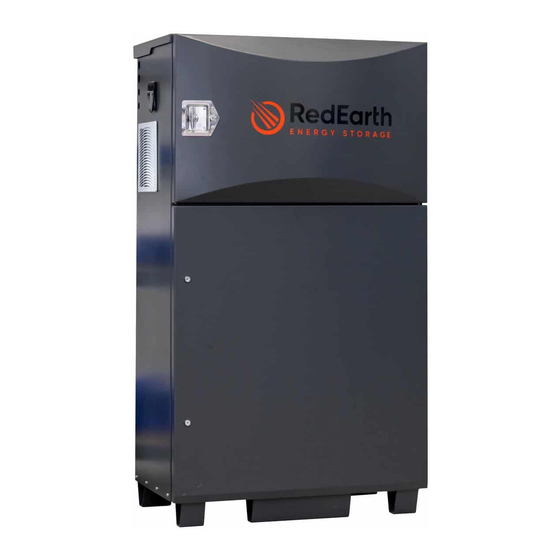
Page 4: Honeybadger Overview
A direct connection from the customers router to the HoneyBadger is also possible. Note: The HoneyBadger is not designed to act as a main switch board for the premises, as it does not include space for additional main & customer circuit breakers or RCDs. The MEN link and Earth connection need to be in place at the premises as required. -
Page 5: Dimensions And Clearance/Positioning Information
According to AS/NZS 5139. Note: if the system is >300mm off the wall then this does not apply. The HoneyBadger is rated for outside installation. It should be installed in a shaded area. HoneyBadger Install Version 2... -
Page 6: Internal Components Description
HoneyBadger Installation Manual Internal Components description The HoneyBadger has two sections. The top area contains the inverters, MPPT’s and all of the electrical switch gear. The bottom section is pre-wired for up to eight of RedEarth’s 4.1kWh Troppo batteries. Each section has a key-lockable door. Note that the keys are not the same for each door. - Page 7 Behind the face plate, are the connection points required for installing the system. This area should only be accessed by qualified personnel. The faceplate is held in place by four screws in the corners of the faceplate. Face plate installed: Face plate removed: HoneyBadger Install Version 2 Page 7 of 32 Issue Date 18/07/2022...
- Page 8 The AC Breakers include a two-pole breaker for connecting a generator as well as a By-pass switch to use if the HoneyBadger has a problem and the load is to be run off the generator alone. Each switch has an identification label directly below it. These are shown below.
- Page 9 Earth Fault alarm. It is located on the right side of the HoneyBadger and is accessed by removing the four screws holding the vent cover in place. The RedPi Lite monitoring equipment installed consists of a RUT240 modem with a RedEarth SIM-card for remote monitoring.
- Page 10 Parts kit - HoneyBadger The HoneyBadger is supplied with documentation and a parts kit box to complete the installation. Documentation: (latest versions are available online at www.redearth.energy)
-
Page 11: Steps To Complete Your Honeybadger Installation
8. Customer Handover – including helping with access to RedEarth EMU app Step 1. Transporting The HoneyBadger system is supplied on a pallet as shown at right. It is fully set-up, factory-tested and ready to run. The system weighs around 392kg with 4x lithium batteries and requires lifting equipment to handle it. -
Page 12: Step 2. Positioning
Wall fixing plates are provided in the parts kit which can be used to ensure the system cannot tip over. The HoneyBadger also has four holes in the base to allow for securing the base. This can be done with Dynabolts or material appropriate screws. - Page 13 Maximum PV array current: Maximum PV open circuit current = 70A for the Victron MPPT 250/100 installed in the HoneyBadger As the Isc of the example 400W panel is 10.12 amps up to six (6) strings can be connected in parallel.
-
Page 14: Step 4. Electrical Connections
NOTE: Before proceeding any further, ensure that all breakers and isolators, as well as those supplying power to the unit, are turned OFF. HoneyBadger Install Version 2 Page 14 of 32 Issue Date 18/07/2022... -
Page 15: Solar
25mm or 32mm glands and conduit. The Appendix A contains a SLD for the system wiring. The AC wiring can be more easily completed by removing the vent on the left side of the HoneyBadger as shown below. - Page 16 4.2.3 Generator Auto-Start The HoneyBadger contains two terminals on the right end of the AC din rail that are covered when the faceplate is installed (see image at right). These terminals are connected to a dry contact that can be programmed to automatically start a generator, or it can be used to activate a signal light indicating that a manual start generator should be started.
-
Page 17: Battery
HoneyBadger Installation Manual Battery The batteries are in the bottom section of the HoneyBadger. Additional batteries can be added in the future Removing or Installing a TROPPO battery: To remove or install a battery follow these steps: 1. Remove the battery cables by pressing the... -
Page 18: Remote Monitoring
Note: if there is no mobile phone coverage then remote monitoring is not possible. Local monitoring: Note that all information available remotely can also be monitored on the local control screen in the HoneyBadger. Detailed instructions are available from Victron at https://www.victronenergy.com/upload/documents/Manual- Color-Control-GX.0.3-EN.pdf... -
Page 19: Step 5: Turn On And Shutdown Procedure
HoneyBadger Installation Manual Step 5: Turn ON and Shutdown procedure Once the HoneyBadger is in place and correctly wired up, you may start the system. To power up the unit follow the steps below: Switch on the battery switch on the top of each lithium battery. -
Page 20: Step 6: Commissioning
There are four ways to change parameters, 1. Using the Colour Control GX display on the HoneyBadger – not all parameters can be changed this way (e.g., generator size) 2. By connecting a laptop with Victron VEConfiguration software downloaded onto it. In addition, a Mk3 device is required to physically connect the laptop to the Victron equipment. -
Page 21: Step 7: Activating Remote Monitoring And Communications
(e.g. via SkyMuster or Starlink services) these can be hard-wired into the RJ45 socket in the rear of the Colour Control GX display. Once internet communication is established there are 2 ways to remotely monitor the HoneyBadger 1. Monitoring via RedEarth’s EMU App: This... - Page 22 Entering all the information requested will help you to get the most from your investment in your HoneyBadger. It will also register your email. You will then immediately be sent an email that allows you to log into the EMU app.
- Page 23 After receiving the invitation email from Victron, follow the prompts to setup your account. Happy monitoring in the VRM portal. Contact details for RedEarth can be found on the last page of this manual. HoneyBadger Install Version 2 Page 23 of 32...
-
Page 24: Step 8: Customer Handover
1. Confirm that the customer has scanned the QR code and entered their information, including an email address. Have the customer download RedEarth’s EMU App. They will be able to register their system an begin monitoring it immediately in the app. Otherwise, provide the customer’s contact details to RedEarth to complete onboarding the customer at a later time. -
Page 25: Services And Options Available For The Honeybadger
HoneyBadger Installation Manual Services and Options available for the HoneyBadger As a RedEarth HoneyBadger system owner you have the choice of joining our customer community. You just need to register your contact details with RedEarth. You can receive regular relevant communications from RedEarth. -
Page 26: Appendix A - Single Line Diagrams
HoneyBadger Installation Manual Appendix A – Single Line Diagrams HoneyBadger Install Version 2 Page 26 of 32 Issue Date 18/07/2022... - Page 27 HoneyBadger Installation Manual HoneyBadger Install Version 2 Page 27 of 32 Issue Date 18/07/2022...
-
Page 28: Appendix B - Technical Specifications
000/100 as the standard inverter. The 48/5000/70-100/100 inverter is available as an option. The Victron SmartSolar series of Charge Controllers are used in the HoneyBadger. The standard is MPPT 250/100. HoneyBadger Install Version 2 Page 28 of 32 Issue Date 18/07/2022... - Page 29 HoneyBadger Installation Manual Troppo-4841 Battery specifications Short-circuit Current (I 0.4 kA 0.8 kA 1.2 kA 1.6 kA 2.0 kA 2.4 kA UN Number 3481 HoneyBadger Install Version 2 Page 29 of 32 Issue Date 18/07/2022...
- Page 30 HoneyBadger Installation Manual HoneyBadger Install Version 2 Page 30 of 32 Issue Date 18/07/2022...
- Page 31 HoneyBadger Installation Manual RedEarth Energy Storage Ltd 15 Fienta Place Darra, Brisbane QLD 4076 Australia Tel: 1800 733 637 Email: support@redearth.energy HoneyBadger Install Version 2 Page 31 of 32 Issue Date 18/07/2022...
- Page 32 HoneyBadger Installation Manual Web: www.redearth.energy HoneyBadger Install Version 2 Page 32 of 32 Issue Date 18/07/2022...
Need help?
Do you have a question about the HoneyBadger and is the answer not in the manual?
Questions and answers