RedEarth HoneyBadger Installation Manual
Home battery system – off-grid, victron + lithium batteries
Hide thumbs
Also See for HoneyBadger:
- Installation manual (32 pages) ,
- User manual (19 pages) ,
- User manual (18 pages)

Related Manuals for RedEarth HoneyBadger


Summary of Contents for RedEarth HoneyBadger
- Page 1 HoneyBadger_InstallationManual HoneyBadger Home Battery System – Off-Grid Victron + Lithium Batteries Installation Manual RE_PROD_0009 Version #1 Page 1 of 20 Issue Date 28/07/2020...
- Page 2 HoneyBadger_InstallationManual RedEarth Energy Storage Ltd 15 Fienta Place Darra – QLD 4076 Australia Tel: +61 7 3279 6707 Email: info@redearth.energy Web: www.redearth.energy RE_PROD_0009 Version #1 Page 2 of 20 Issue Date 28/07/2020...
- Page 3 HoneyBadger_InstallationManual Safety WARNING: Working on the inside of the HoneyBadger system is restricted to qualified personnel. In Australia this is typically qualified electricians with CEC accreditation for Solar and Battery. The wiring diagrams and installation instructions are given as a guide only and compliance to appropriate standards is the responsibility of the installer.
- Page 4 (either auto or manual start) The HoneyBadger system is designed to be installed either inside or outside, ideally in a shaded area against a wall. A changeover switch is included in case of system failure. In this case the loads can then be run off a generator until the system is operational again.
-
Page 5: Physical Specifications
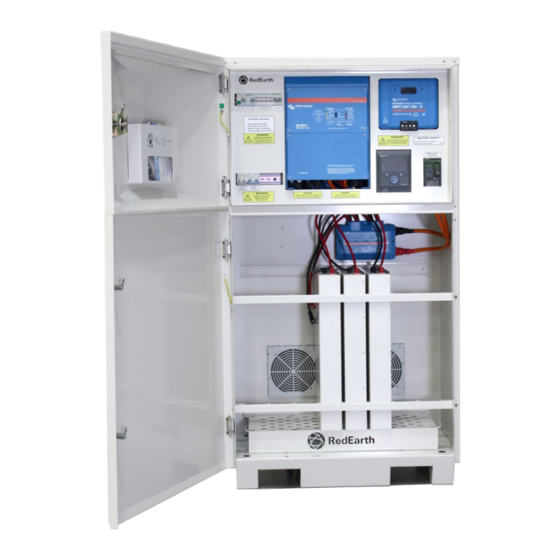
HoneyBadger_InstallationManual Physical Specifications HoneyBadger Weight: 392kg with 4x Lithium batteries (42kg per battery) Dimensions w/ door closed: 169 H x 94 W x 65 D [cm] Dimensions w/ door open: 169 H x 104 W x 144 D [cm] HoneyBadger Minimum Clearance... - Page 6 Components Inside The HoneyBadger has two areas, one for the batteries and the other for the switches and electronic equipment. Each section has a key-lockable double door. The top enclosure contains all of the electric-electronic equipment, switches and AC connection terminals.
- Page 7 HoneyBadger_InstallationManual Components Amongst the AC Breakers you will find several AC protective, isolation and the changeover switch. Each device contains an identification labelled directly above it. Identification can also be seen in the picture below. Directly below are the DC Breakers responsible for isolating the PV array and the MPPT. RE_PROD_0009 Version #1 Page 7 of 20 Issue Date 28/07/2020...
- Page 8 Attached to the top of this chamber there are two fully enclosed battery busbars with the correct amount of battery connecting cables. The HoneyBadger comes fully equipped with the following items. • HoneyBadger pre-wired enclosure • Victrion Quattro inverter •...
-
Page 9: Installation
5. Finalizing 1. Transporting The HoneyBadger system is supplied on a pallet as shown at right. It is fully set-up and ready to run. The system weighs around 392kg with 4x lithium batteries and requires lifting equipment to handle it. The system can only be lifted from the base. - Page 10 Securing the system to the wall is done by screwing through the hole on the left and right corner of the systems roof. The HoneyBadger also has four holes in the base to allow for securing. This can be done with dynabolts or material appropriate screws.
- Page 11 NOTE: The MCB is rated at 50A, be sure to use appropriate cabling. Generator Auto-Start and Charger HoneyBadger contains two terminals on the left end of the top DIN rail that do not appear when the faceplate is installed. These terminals are connected to a dry contact that can be programmed to automatically start a generator, or it can be used to activate a signal light indicating that the manual start generator is required.
- Page 12 If monitoring is provided and the customer wishes to monitor their system via the VRM APP or on their PC, then the customer will need to provide an email address to RedEarth. They will then receive login details emailed to them. This email address can be provided prior to installation.
- Page 13 HoneyBadger_InstallationManual Installation 4.1. Installing SwitchDin To install the SwitchDin device, unplug the antenna from the droplet, pass the same plug through the hole identified with the “EXTERNAL ANTENNA” sticker, re-plug the antenna in the same port and then tighten the gland onto the unit. Once this is done, place the antenna in a open area with good cellular reception.
- Page 14 NOTE: To do these changes, you will need a MK3 device and the VE Config program. The MK3 device does not come with the HoneyBadger as a standard tool. However, it may be purchased if required. The VE Config program can be downloaded for free Victron’s web page (https://www.victronenergy.com.au/)
-
Page 15: Start-Up / Shutdown Procedure
4 Switch on the PV Array #1 and #2 Isolator 5 Position the Changeover switch upwards (position 1); 6 Turn ON all AC circuit breakers The shutdown procedure is shown below. This label is affixed to the inside of the HoneyBadger. RE_PROD_0009 Version #1 Page 15 of 20... - Page 16 Phone Tech support on +61 487 002 451 or +61 7 3279 6707. RedEarth also provides training in our facility in Brisbane. Training can potentially be arranged at your facilities if requested.
- Page 17 HoneyBadger_InstallationManual Single Line Diagram (SLD) RE_PROD_0009 Version #1 Page 17 of 20 Issue Date 28/07/2020...
- Page 18 HoneyBadger_InstallationManual Single Line Diagram (SLD) RE_PROD_0009 Version #1 Page 18 of 20 Issue Date 28/07/2020...
-
Page 19: Technical Specifications
HoneyBadger_InstallationManual Technical Specifications Victron Quattro inverter/charger – Selected specifications. The HoneyBadger uses the 48/5000/70- 100/100 Quattro. The Victron SmartSolar series of Charge Controllers are used in the HoneyBadger. The standard is MPPT 250/100. RE_PROD_0009 Version #1 Page 19 of 20... - Page 20 HoneyBadger_InstallationManual Technical Specifications Specifications of the PowerPlus Energy Life4833P lithium battery module RE_PROD_0009 Version #1 Page 20 of 20 Issue Date 28/07/2020...
Need help?
Do you have a question about the HoneyBadger and is the answer not in the manual?
Questions and answers