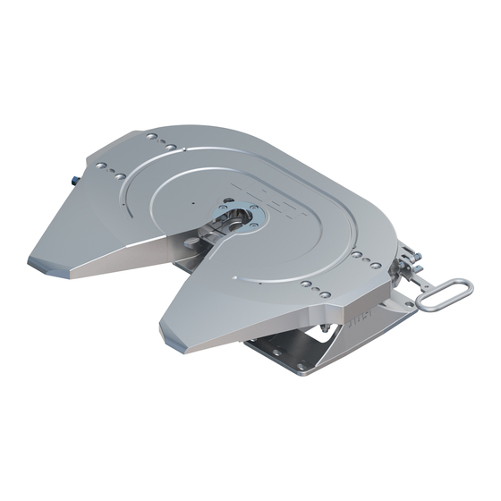
jost JSK 37 Repair Instructions
Replacing the sensor set
Hide thumbs
Also See for JSK 37:
- Replacement procedures (2 pages) ,
- Replacement procedures (2 pages) ,
- Installation and operating instructions manual (24 pages)

Subscribe to Our Youtube Channel
Related Manuals for jost JSK 37


Summary of Contents for jost JSK 37
- Page 1 Repair instructions Replacing the sensor set JSK 37/JSK 40/JSK 42 Daimler version JSK_12_032...
-
Page 2: Table Of Contents
This repair manual is designed to act as a guide to Usage completing repair work on our sensor set. Specification It is essential that you use JOST spare parts. 3 General Modifications of any kind will render both the 4 Standard and special tools and warranty and the type approval void. - Page 3 Safety information The relevant safety regulations in your country (for example Health & Safety at Work) apply for working with sensor-enabled fifth wheel couplings and vehicles. The relevant safety instructions included in the vehicle and semi-trailer's operating instructions must also be complied with.
-
Page 4: Correct Use
JOST fifth wheel couplings are specified to comply with Directives 94/20/EC and Regulation ECE R55-01 in class 50 and are to be used only in conjunction with kingpins of class H50 and class J mounting plates or comparable licensed equipment. -
Page 5: General
General Conversion work must be carried out by trained personnel in suitable workshops. Repair work is to be carried out using suitable tools and state of the art methods. Clean all parts thoroughly before assembly. Ensure that electrical plug connectors or compressed air connectors do not become soiled. -
Page 6: Standard Tools
SW 24 SW 36 D4.2 D5.5 150 mm 4.2 Special tools SK2702-10 SKE00863000 - Multimeter/resistance measuring device 4.3 Auxiliary materials We recommend high-pressure grease (EP), e.g. JOST high-performance lubricant (Art. No. SKE 005 670 000). ZDE 199 007 105 03/2013... -
Page 7: Checking The Function Of The Sensors
(see Section 5.2 and 5.3.1). Replace worn and faulty components (see Section 6 and To open the fifth repair instructions JSK 36/JSK 37 and JSK 40/JSK 42 on wheel coupling the JOST website at www.jost-world.com). Locking sensor cannot be switched. Check the magnet and sensor on the fifth wheel coupling handle (see Section 5.2 and 5.3.1). -
Page 8: Basic Settings And Visual Inspection
150 mm 150 mm 19,0 -20,5 mm 32,0 -33,5 mm JSK_12_033 JSK_12_034 Wear part JSK 37C without plastic liner Wear part JSK 37 with plastic liners and JSK 40/JSK 42 with and without plastic liners ZDE 199 007 105 03/2013... - Page 9 Checking the function of the sensors Before checking the sensors' function, the following components must first be inspected for visible mechanical damage: JSK 40/JSK 42 JSK 37 JSK_12_035 Semi-trailer detection sensor cover Plug Cable to the sensor set JSK 40/JSK 42...
-
Page 10: Diagnostic Tester
Checking the function of the sensors Close the coupling. 5.3 Diagnostic tester Measure the contact resistance on the plug un- The Daimler diagnostic tester can also be used for der the fifth wheel coupling as follows, moving the following checks. the handle on fifth wheel couplings of type JSK 40/JSK 42 and the traps on fifth wheel cou- If no tester is available, the test can also be... - Page 11 Checking the function of the sensors 5.3.2Checking the kingpin sensor 5.3.3Checking the semi-trailer detection sensor Switch the vehicle's ignition on. The sensor's function LED points downwards when installed. Consequently, the LED can be observed Open the coupling (no kingpin engaged). with the help of a mirror.
-
Page 12: Repair Work
With the diagrams the work steps should be carried coupling (yellow-coloured surface). See the out in alphabetical order (e.g. a, b, c). Assembly is illustration JSK 37 and JSK 42 as an example. carried out correspondingly in reverse order. Instructions for assembly are identified in the diagram number or in the diagram itself with a diamond ◊. -
Page 13: Removing The Cable Ties
Repair work 6.2 Removing the cable ties Depending on the design, the cable routing, the position and number of the cable ties and cable clamps may vary. You can see different designs in Fig. A. JSK_12_047 Trim and remove the cable tie ... - Page 14 Repair work JSK_12_005 To secure the line during installation, use the positions shown in Fig. 1 and 2, see previous page. ZDE 199 007 105 03/2013...
-
Page 15: Removing The Semi-Trailer Sensor
Repair work 6.3 Removing the semi-trailer sensor JSK_12_006 1/2´´ SW 36 1/2´´ 30 Nm 16 mm 6.5 Nm JSK_12_007 JSK_12_008 Remove the screw (1) on the retaining plate (4). Loosen the securing nuts (7) on the semi- trailer sensor (6). To ensure better accessibility, loosen the hook spring (2) on the eye bolt (3). - Page 16 Repair work 6.4 Installing the semi-trailer sensor Components in the semi-trailer sensor unit: JSK_12_009 Screw M16x10 with washer Holders Semi-trailer sensor M30 Nut SW36 Cable splice (optional) Protective cap Installation is carried out correspondingly in the reverse order. Note the installation measures, see Fig.
-
Page 17: Removing The Connecting Socket
Repair work 6.5 Removing the connecting socket On variants with a connecting socket attached to the fifth wheel coupling, this must be removed. JSK_12_010 JSK_12_011 Slide the safety slide (10) in the direction of the arrow (C) away from the plug. ... -
Page 18: Removing The Kingpin Sensor
C marked previously. repair instructions can be obtained from the Measure the calculated setting dimension. JOST website www.jost-world.com. Guide a new kingpin into the fifth wheel coupling and ensure that the lock is closed and secured, as shown in the installation and operating in- structions. -
Page 19: Removing The Locking Sensor Jsk 40/Jsk
Repair work 6.8 Removing the locking sensor JSK 40/JSK 42 1/2´´ To remove the locking sensor, the handle must be removed. 1/2´´ SW2.5 JSK_12_016 Insert the kingpin sensor (15) so far into the hole until it rests on the gauge (16). ... -
Page 20: Fitting The Locking Sensor Jsk
Repair work 6.9 Fitting the locking sensor JSK 42 Installation is carried out correspondingly in the reverse order. Note the difference between Figures 1 and 2! JSK_12_019 Remove the pull lever (19) from the fifth wheel coupling. JSK_12_022 1/2´´ Without plastic liners: 1/2´´... -
Page 21: Removing The Locking Sensor Jsk
Repair work 6.10 Removing the locking sensor JSK 37 JSK_12_048 6.11 Fitting the spare part - creating a repair drill hole D5.5 SW 17 JSK_12_025 Remove the head from blind rivet (23) (D5.5 drill) and undo the screw (24). - Page 22 Deburr and bevel the drill hole. Also note the "Repair instructions for the Cut the M5 thread. JSK 37 fifth wheel coupling" Drill hole for metric thread: Tighten the securing nut (28) to hand tight- ness. - Core hole diameter: Diameter 4.2 mm...
-
Page 23: Add-On Parts For Locking Sensor
Disposal instructions The mounted parts are valuable raw materials that 6.12 Add-on parts for locking sensor can be recycled. JSK 37 They can be split into plastic/rubber and metallic materials. Plastic and rubber is labelled in accordance with VDA recommendation 260. - Page 24 Siemensstraße 2, D-63263 Neu-Isenburg, Telefon +49 6102 295-0, Fax +49 6102 295-298, www.jost-world.com ZDE 199 007 105 03/2013...
Need help?
Do you have a question about the JSK 37 and is the answer not in the manual?
Questions and answers