
Related Manuals for jost JSK Series


Summary of Contents for jost JSK Series
- Page 1 Sensor JSK Sensor JSK Installation and operating instructions Installation and operating instructions...
- Page 2 MUB 007 001 M01 (REV-C) 07/2020 Sensor JSK...
-
Page 3: Table Of Contents
Table of contents 1 Explanation of symbols..........4 2 Safety information............2.1 Safety information for operation......5 2.2 Safety information for installation......6 3 Intended use..............7 4 Installation..............8 4.1 List of components........... 8 4.2 Display............... 9 4.3 Connecting connection cable........10 5 Operation.............. -
Page 4: Explanation Of Symbols
Explanation of symbols WARNING! Means that death, serious physical injury or significant material damage can occur if the relevant safety instruc- tions are not followed. ATTENTION! Means that slight physical injury or material damage can occur if the relevant safety instructions are not fol- lowed. -
Page 5: Safety Information
G50 JOST fifth wheel cou- The relevant safety regulations in your country (for example Health plings. -
Page 6: Safety Information For Installation
Safety information Safety information for installation The assembly work may only be completed by authorised specialists. Follow the safety instructions for working on the vehicle’s electrical system as set out in the assembly and modification instructions issued by the vehicle’s manufacturer. The battery must be disconnected before starting any work on the vehicle’s electrical system. -
Page 7: Intended Use
The JOST display is described below. The descriptions apply accord- The sensor coupling display can be shown on the JOST display or ingly to the display on the instrument panel. on a display integrated in the instrument panel of the vehicle. -
Page 8: Installation
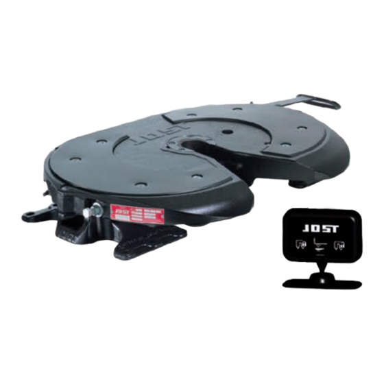
Installation List of components JSKC/02 Display Plug (display) Connection cable Plug (fifth wheel coupling) Semi-trailer sensor, only with sensor coupling model with 3 sensors Locking sensor, switch magnet King pin sensor Power supply connection MUB 007 001 M01 (REV-C) 07/2020 Sensor JSK... -
Page 9: Display
Installation Display JSKC/28 ADVICE! Install the display (1) in the driver’s field of vision. The display's installation foot has an adhesive surface and can be affixed into position. The affixing area in the vehi- cle must be dry and free of dust and grease. Alterna- tively the installation foot may be screwed into position. -
Page 10: Connecting Connection Cable
Installation Connecting connection cable ATTENTION! The safety information set out in section 2.2 must be observed to prevent damaging the vehicle's electrical system. Connect the plug (2) to the display. Route the power supply connection (8) to the point approved by the vehicle manufacturer and connected there (see con- nection diagram in section 4.1). -
Page 11: Operation
Operation ADVICE! The figures partially show sensor couplings with 2 or 3 sensors, however, descriptions apply to both versions. Self-diagnostic Operating indicator (fifth wheel coupling open/ ready for coupling) The sensor coupling carries out a self-diagnostic test when the igni- tion is switched on. -
Page 12: Operating Indicator (Faults)
The red "Fifth wheel coupling A system error has occurred. closed" indicator will flash and an alarm will sound. The JOST fifth wheel coupling is not correctly locked, i.e. the fifth-wheel coupling is closed, but the king pin is not engaged or not detected by the system. -
Page 13: Sensor Coupling Process
Operation Sensor coupling process The fifth wheel coupling is open and ready to cou- ple. JSKC/38 Drive the tractor unit under the semi-trailer. Raise the fifth wheel using the air suspension until the fifth wheel coupling plate contacts the skid plate. For a sensor coupling with skid plate detection (3 sensors), the display now switches on automatically. - Page 14 Operation Reverse the tractor unit until the fifth wheel cou- pling closes. The green "Fifth wheel coupling closed" display will be lit. The fifth wheel coupling is correctly closed. ADVICE! The display will go dark after 2 minutes. WARNING! The driver must check that the semi-trailer has been connected properly.
-
Page 15: Sensor Uncoupling Process
The fifth wheel coupling is correctly closed and locked. Open the fifth wheel coupling locking mech- anism. “JOST lettering” and “Open” are flashing red. ADVICE! After a time limit of 2 minutes has elapsed the alarm will stop and the red LEDs will be constantly lit until the tractor unit has been driven out. - Page 16 Operation Drive out the tractor unit as usual, lowering the air suspension. The red indicators go out. ADVICE! The display will switch off completely after approx. 10 seconds. MUB 007 001 M01 (REV-C) 07/2020 Sensor JSK...
-
Page 17: Troubleshooting
Troubleshooting ADVICE! In order to remedy malfunctions, see also the repair instructions for the sensor set. General malfunctions Fault Cause Remedy Display non-functional after Plug connections loose or not connected Check the plug connections for the cabling between starting (ignition “ON”). correctly. - Page 18 Troubleshooting Fault Cause Remedy Plug connections loose or not connected cor- Check the plug connections for the cabling between the rectly. fifth wheel coupling and the electronic display. ADVICE! All the contacts must be engaged uniformly in the plugs. Ensure that the plug connections are engaged correctly.
- Page 19 Troubleshooting Fault Cause Remedy The fifth wheel coupling is not adjusted cor- Check fifth wheel coupling and adjust according to instal- rectly or is worn. lation and operating instructions of fifth wheel coupling. The king pin is worn to below the maximum Replace the king pin and check the locking mechanism wear limit.
-
Page 20: Malfunctions During Coupling Up
Troubleshooting Malfunctions during coupling up Fault Cause Remedy The fifth wheel coupling is not closed cor- Check the status of the locking mechanism, adjust the rectly or the king pin is not in the correct locking mechanism if necessary and reconnect the semi- position. -
Page 21: Malfunctions During Uncoupling
Troubleshooting Fault Cause Remedy The fifth wheel coupling has been locked Open the fifth wheel coupling and reconnect the semi- manually without the king pin. trailer if necessary. ADVICE! The skid plate must rest on the fifth wheel cou- pling without a gap. King pin sensor defective. -
Page 22: Maintenance
Maintenance ADVICE! To ensure the sensor is functioning, check wearing parts as described in the installation and operating manual for the JSK 34, JSK 36, JSK 37 or JSK 42 and adjust if neces- sary. Cleaning the sensor fifth wheel coupling Clean all grease and dirt deposits off the functional surfaces of the sensors (kingpin sensors and semi-trailer sensor). - Page 24 Member of JOST World JOST, Germany, Tel. +49 6102 295-0, tkd-technik@jost-world.com, www.jost-world.com MUB 007 001 M01 (REV-C) 07/2020 • 2.1 1006229...
Need help?
Do you have a question about the JSK Series and is the answer not in the manual?
Questions and answers