Table of Contents
Advertisement
Quick Links
Advertisement
Table of Contents

Summary of Contents for Satron Instruments VC
- Page 1 VC Quick Start Guide SATRON INSTRUMENTS INC...
-
Page 2: Table Of Contents
Setting the Date and Time ............................. 6 Setting the Range for IO1 ............................... 7 Setting the Range for I02 (VCT) ............................. 8 Setting the Range for I02 (VC Multichannel) ........................ 9 Installing a Sample Toggle Switch Unless Supplied by Satron..................10 Sample Data Collection ..............................10 Sample Data Collection at the RDU ..........................11... -
Page 3: Introduction
The VCT family of transmitters utilize the latest LED based strobe techniques using multi-frequency light measurement. The VCT measures Consistency in the 0 to 12%CS range. The VC multichannel measures Consistency on channel one and one of the following measurements on channel two: Ash, Brightness, Freeness, Kappa, Fiber Length or Shives Content. -
Page 4: Mounting The Transmitter
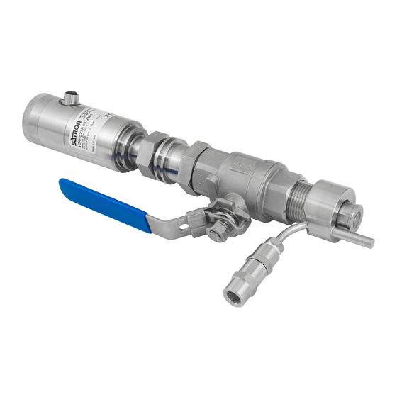
(a) unless the ball valve is closed! Electrical Connections This figure shows a combination of many of the components of the VC family. An order will contain a combination of these components along with any additional components associated with special orders. - Page 5 Supply voltage to the transmitter is 24 Vdc and requires up to 200 mA current. It is recommended that a shielded twisted-pair cable is used as a signal cable. The signal cable should not be installed near high- voltage cables, large motors or frequency converters.
- Page 6 Second mA (IO2) loop connection (2-wire) Digital input – Digital output (relay) 4 – 20 mA input Digital output Device enclosure (K) connection to PLC Connection Box (K) 250Ω – – Digital input 4 – 20 mA inputs...
-
Page 7: Initial Set-Up
Initial Set-up The initial set-up consists of three steps. 1. Set the Date and Time 2. Set the operating range for Consistency (IO1). 3. If a Sampling Switch was not purchased and a user supplied Switch is not being added, skip this step. If a user supplied Sampling Switch is added, you must configure the Sample Digital Input (DI1). -
Page 8: Setting The Range For Io1
The date sub-menu will appear first and is in the format of DDMMYYYY. Use the UP/DOWN arrows to set the day. then press ENTER to move to the month. Use the UP/DOWN arrows to set the month, then press ENTER to move to the year. -
Page 9: Setting The Range For I02 (Vct)
Use the UP/DOWN arrows to place the decimal separator in the proper location and press ENTER. A separator will appear to indicate the digit that will be modified. Use the UP/DOWN arrows to change the number and press ENTER. The separator will move to the right position. Press ENTER until the right-hand digit is indicated and press ENTER one more time. -
Page 10: Setting The Range For I02 (Vc Multichannel)
Press the Esc button until the PV reading in the main menu is displayed. Setting the Range for I02 (VC Multichannel) Starting at the default PV display value; Press the ESC button. Press the ENTER button to enter the Configuration sub-menu. -
Page 11: Installing A Sample Toggle Switch Unless Supplied By Satron
Press the Esc button until the PV reading in the main menu is displayed. Installing a Sample Toggle Switch Unless Supplied by Satron. An external Sample Toggle Switch simplifies the automatic collection of transmitter readings when a sample is being collected. It is simple on/off operation so that when the switch is on, the transmitter readings are averaged until the switch is toggled off. -
Page 12: Sample Data Collection At The Rdu
Excel spreadsheet. This spreadsheet along with the sif-file that is extracted from the transmitter should be sent to Satron for analysis. Satron will send back the calibration coefficients to insert into the VC multichannel for this application. -
Page 13: Data Collection And Data Retrieval
Data Collection and Data Retrieval The mill's standard for collecting consistency samples should be enough. The TAPPI T 240 standard is a good reference. Note: The sample extraction location should be located as close as possible to the transmitter for the best results. -
Page 14: One Point With An Offset Correction
An OK message will appear in and the display will automatically return to the Sample sub-menu. Press the ESC key until the PV reading in the main menu is displayed. One Point with an Offset Correction Use the following procedure to calibrate consistency with one sample point (you can also use the water point stored in the transmitter as the first sample point): Starting at the default PV display value;... -
Page 15: Sampling For Vc Multichannel: An Advanced Calibration
There are two output channels in the VC multichannel, one for Consistency of the stock and the other for the specific parameter being measured. Kappa, Ash, Freeness. Brightness etc. must be carefully determined in the laboratory and the results correlated to the transmitters measured variables. -
Page 16: Creating The .Sif - File
Creating the .sif - File The SILogAdvisor software provided by Satron Instruments is used to create the .sif (Satron Information File) file. This software is downloaded from the Satron website and installed on a laptop that can be connected to the mini USB connector inside the transmitter cap (1). - Page 17 Use the UP/DOWN arrows to move to the Calibration sub-menu and press ENTER button and the RECIPE sub-menu Will appear. Press ENTER to enter the sub-menu. The MA 1? menu Item will appear Press ENTER and the OFFSET sub-menu will appear. Press ENTER to enter the OFFSET sub-menu.
-
Page 18: Entering Consistency Tuning Parameters With Silogadvisor
First attach the laptop to the transmitter, start the SILogAdvisor software and connect as directed previously. Click the File - drop down button and select “VC Consistency calibration simulation” from the menu. On the device section of the VC Consistency calibration... -
Page 19: Calculating Consistency Parameters
SILogAdvisor software. Attach the laptop to the transmitter and connect as directed previously. Click the “File” drop down button and select “VC Regression Simulation” at the bottom of the menu. The VC Regression simulation window will open. There are three channels for entering parameters. - Page 20 If you wish to verify that the values were written, click the “Disconnect” button and then reconnect to the transmitter, reopen the VC regression simulation window click on the “Read” button (3) above the PV2 column and the values stored in the...
Need help?
Do you have a question about the VC and is the answer not in the manual?
Questions and answers