
Related Manuals for BST CLS Pro 600


Summary of Contents for BST CLS Pro 600
- Page 1 Web Guiding System Installation and Operating Manual CLS Pro 600 Line and Contrast Sensor MD.323.EN.08 Translation of the Original Manual...
- Page 2 BST eltromat International GmbH Heidsieker Heide 53 D-33739 Bielefeld Tel.: +49 (0) 5206 999 0 Fax: +49 (0) 5206 999 999 E-Mail: info@bst-international.com Internet: www.bst-eltromat.com This documentation is protected by copyright. The translation as well as reproduction and distribution in any form is forbidden without the approval...
-
Page 3: Table Of Contents
Sensor ......................... 35 4.2.1 Enclosure Sockets ....................... 35 Service Indicator Displays ................... 36 4.3.1 Bus Status LEDs ...................... 36 4.3.2 Unit Status LED...................... 37 Setting the DIL Switches.................... 37 5 Commissioning.................... 38 Menus ......................... 39 CLS Pro 600 – Line and Contrast Sensor... - Page 4 Sensor ......................... 84 9.1.1 Environmental Conditions .................. 84 9.1.2 Power Supply ...................... 84 9.1.3 Digital Inputs ....................... 84 9.1.4 Digital Outputs ...................... 84 9.1.5 Analogue Output...................... 84 9.1.6 Measuring Window Cover .................. 85 CLS Pro 600 – Line and Contrast Sensor...
- Page 5 D Appendix 4 - BST eltromat STB 1 Connections .......... 104 Installation Instructions For EMC-Wiring .............. 105 E Appendix 5 - Teach-in Template .............. 107 Aligning the Teach-In Template in Front of the CLS Pro 600 ........ 108 CLS Pro 600 – Line and Contrast Sensor...
-
Page 6: About This Document
Here you can find how to avoid the danger. ► NOTICE Danger that may lead to damage to assets! There is no risk of injury. Here you can find how to avoid the danger. ► 6/108 CLS Pro 600 – Line and Contrast Sensor... -
Page 7: Symbols
Observe the accompanying documents (e.g. order confirma- ► tion) for this system and the operating instructions of the en- tire system. The latest version of these instructions can be obtained in all available languages at: www.bst-eltromat.com CLS Pro 600 – Line and Contrast Sensor 7/108... -
Page 8: Description
■ Web edges ■ The CLS Pro 600 line and contrast sensor has been designed to be fitted in another machine or to be combined with other machines to form a complete machine in the sense of the Directive 2006/42/EC (machine directive). Start-up of the system is forbid-... -
Page 9: System Description
System Description 2.3.1 System Design General Information The CLS Pro 600 consists of the sensor and the removable control panel. The sensor enclosure holds the entire electronics and the control panel and controller connections. Sensor with Fitted Control Panel The sensor is operated via the control panel, which is fitted to the sensor in the factory. -
Page 10: Functional Principle
The actuator will drive the guiding device (rotating frame or swivelling roller guide) until the material web returns to its set point position. The CLS Pro 600 sensor can be used in the following configura- tions: 10/108... - Page 11 Application with ekr 500 digital controller: CAN bus connection (optional) Customer's machine controller Sensor CLS Pro 600 BST eltromat Signal with control panel Terminal Box1 (optional) Fig. 5: Application with ekr 500 digital controller CLS Pro 600 – Line and Contrast Sensor 11/108...
-
Page 12: Terms Used In This Manual
Terms Used in this Manual 2.4.1 General Information In principle, the windows displayed on the keyboard’s graphics display are laid out as follows: Fig. 7: Display Layout ① Status Bar ② Footer 12/108 CLS Pro 600 – Line and Contrast Sensor... -
Page 13: Set Position
Contrast Quality (graphical) ③ Standard SET Position The deviation will be faded in as plaintext during displacement of the set position. The deviation can take positive values and negat- ive values as well. CLS Pro 600 – Line and Contrast Sensor 13/108... -
Page 14: Measuring Range
Fig. 10: Measuring Range 2.4.4 Search Area The search area is a section within the measuring area. The line / edge that has to be evaluated and controlled afterwards is located in this section. 14/108 CLS Pro 600 – Line and Contrast Sensor... -
Page 15: Status Bar
The edge position on the left of the display must be used for set- ting up the First Edge. Fig. 11: First Edge / Second Edge ① First Edge ② Second Edge The second edge is used for setting up the Second Edge CLS Pro 600 – Line and Contrast Sensor 15/108... -
Page 16: Control Panel
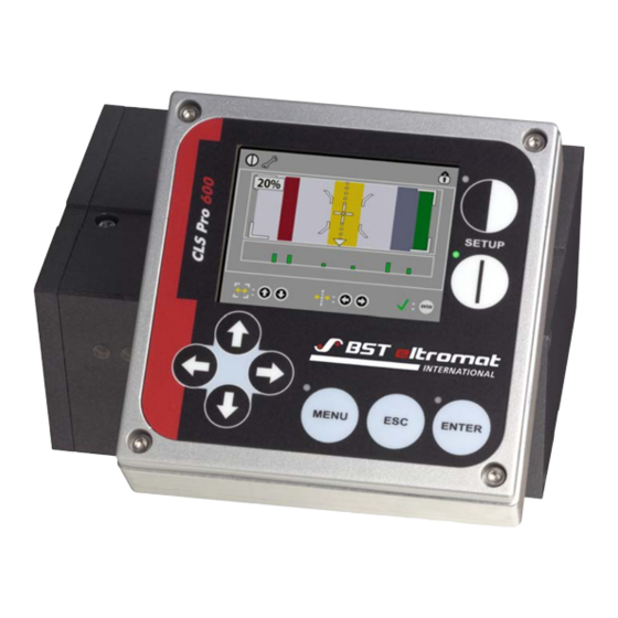
Description Control Panel Fig. 12: Control Panel The control panel contains all of the display and operating con- trols needed to operate the CLS Pro 600. 2.5.1 Graphic Display Different parameters as well as main and quick menus (depending on the mode selected) are displayed on the control panel’s screen during operation. -
Page 17: Safety Information
BST-eltromat equipment in the production machine, these include: There must always be a safe distance between the BST-eltro- ■ mat equipment and the machinery already installed on-site, such as machine panels, building structures, etc. - Page 18 ð Only then can the relevant work be undertaken! WARNING Caution! Do not use the chassis or machine frame as a climbing aid or a ste- pladder. Do not remove any of the safety devices. 18/108 CLS Pro 600 – Line and Contrast Sensor...
-
Page 19: Laser
This laser will not cause eye damage, even after long radiation periods and even if other optical tools (lenses, etc.) are used in the beam’s path. Emissions The A-rated equivalent continuous sound level of the equipment is less than 70 dB(A). CLS Pro 600 – Line and Contrast Sensor 19/108... -
Page 20: Assembly
Sensor with supplied holder A square holder bar has to be used with the holder supplied in the package for the CLS Pro 600 sensor. Two sizes can be used, 25x25 mm and 35x35 mm. The holder consists of a special holding device that enables both sizes to be used. -
Page 21: Installing The Sensor Using A Holder Supplied By The Customer
Fig. 14: Installing the Sensor Using a Holder Supplied by the Customer ① M6 / 7 deep securing threads for securing holder provided by customer (on both sides) CLS Pro 600 – Line and Contrast Sensor 21/108... -
Page 22: Setting The Gap Between The Sensor And The Sensing Roller
(each one offset by 90° from the other) (see diagram). Fig. 16: Turning the Control Panel The sensor is prepared for installation in position ① when de- livered from the factory. 22/108 CLS Pro 600 – Line and Contrast Sensor... - Page 23 1. Unscrew the four control panel fastening screws. 2. Carefully pull the control panel upwards and away from the sensor. 3. Turn the control panel into the required position (see illustra- tion above). Fig. 18: Cut-out ⑥ Cut-out CLS Pro 600 – Line and Contrast Sensor 23/108...
-
Page 24: Rotating The Control Panel
④. 2. Afterwards tighten the fastening screws ③ again and screw the control panel ① onto the mounting plate ②. NOTICE Caution! Don’t crush or clamp the connecting cable! 24/108 CLS Pro 600 – Line and Contrast Sensor... -
Page 25: Installing The Control Panel
Procedure: See chapter 3.3.4. Please note: A CLS Pro 600 securing kit, which is available as an op- tion, is needed to install the control panel in a control console (BST eltromat Order-No. 133 459). - Page 26 2. Pull out the holder. 3. The next procedures depend on the type of installation. Refer to section 3.3.3 for a wall mounting or section 3.3.4 for a con- sole mounting. 26/108 CLS Pro 600 – Line and Contrast Sensor...
-
Page 27: Wall Mounting
Preparations: Fig. 22: Unplug the connecting cable ① Control Panel Connecting Cable ② Plug X100 1. Unplug the plug ② of the control panel connecting cable ① from the sensor (plug X100). CLS Pro 600 – Line and Contrast Sensor 27/108... - Page 28 2. Unscrew the holder’s four securing screws ③ from the sensor enclosure. Fig. 24: Remove holding ring and control panel ⑤ Holding Ring 3. Pull the holding ring ⑤ and control panel sideways out of the groove in the sensor enclosure. 28/108 CLS Pro 600 – Line and Contrast Sensor...
- Page 29 These screws will be needed for the wall mounting later on. 5. Pull the control panel ⑦ out of the mounting plate ⑥. Now pull the connecting cable and the plug carefully through the cut-out in the mounting plate. CLS Pro 600 – Line and Contrast Sensor 29/108...
- Page 30 3. Use the optional extension cable to connect the control panel to the sensor. 4. Plug the extension cable connector into the sensor’s X100 socket. 30/108 CLS Pro 600 – Line and Contrast Sensor...
-
Page 31: Console Installation
Fig. 27: Installation cut-out Preparations: Please note: A securing kit, which is available as an option, is needed to install the control panel in a control console (BST eltro- mat Order-No. 133 459). Fig. 28: Pull out the plug ① Control Panel Connecting Cable ②... - Page 32 ④ Plug 2. Unscrew the four control panel securing screws and put them aside. These screws will be needed for the console mounting later on. Fig. 30: Take off the control panel 32/108 CLS Pro 600 – Line and Contrast Sensor...
- Page 33 The four hexagon screws that secured the control panel to the sensor when the unit was delivered can be used for this. Fig. 32: Top View ③ Threaded Pin ④ Securing Plate ⑤ Control Panel CLS Pro 600 – Line and Contrast Sensor 33/108...
- Page 34 5. Use the optional extension cable to connect the control panel to the sensor. 6. Plug the extension cable connector into the sensor’s X100 socket. 34/108 CLS Pro 600 – Line and Contrast Sensor...
-
Page 35: Installation
STB 1) connection box with External lighting, switched ■ terminal strip for onsite connec- against +24 V tions; see appendix 4 for layout Error O/P, switched ■ against +24 V CLS Pro 600 – Line and Contrast Sensor 35/108... -
Page 36: Service Indicator Displays
The device is functioning properly. There NO ERROR is no error present. FLASHES 3x SYNC ERROR No SYNC message is received. The interface controller is in Bus OFF BUS OFF mode. 36/108 CLS Pro 600 – Line and Contrast Sensor... -
Page 37: Unit Status Led
NMT master and bus system sync generator. S4.4 = Set up the sensor to work with ekrPro Com60 / ekr 500 Plus / ekr 500 digital / EKR 1500 / CCD Line Guider. CLS Pro 600 – Line and Contrast Sensor 37/108... -
Page 38: Commissioning
Always check the connection cable and the plug in this case. Furthermore, you can also read whether the terminator res- istor has been set up correctly or not. 38/108 CLS Pro 600 – Line and Contrast Sensor... -
Page 39: Menus
2. Press ENTER to confirm the selected number / selected letter. 3. If the entry consists of several places then you must use the right arrow key to select the next place. The entry must now be made as described above. CLS Pro 600 – Line and Contrast Sensor 39/108... - Page 40 1. Select the required parameter. The current status will be dis- played in the footnote at the bottom of the setting up window. 2. Use the up / down arrow keys to activate T or deactivate £ the function. 40/108 CLS Pro 600 – Line and Contrast Sensor...
- Page 41 The relevant path going to the description of a specific main menu section will be displayed alongside the description. Only the relev- ant window will be displayed in the actual description. Example: Proceed as follows to set up the sensor parameters: CLS Pro 600 – Line and Contrast Sensor 41/108...
- Page 42 2. Open the main menu first. 3. Now select the configuration sub-menu. 4. Select sensor and then open the setting up window. ð The path details will then be displayed in the description \configuration\sensor. 42/108 CLS Pro 600 – Line and Contrast Sensor...
-
Page 43: Commissioning With A Controller
Explanations for the specific menu sections can be found in Sec- tion 6.7‚ Signification of the main menu parameters. Commissioning With a Controller 5.2.1 ekrPro Com60 See Quick Reference Guide: Web guiding system ekrPro Com60 with CLS Pro 600 (MD.337.01.xx). CLS Pro 600 – Line and Contrast Sensor 43/108... -
Page 44: Ekr 500 Plus / Ekr 500 Digital
Web guiding system ekr 500 Plus/digital with CLS Pro 600 (MD.341.01.xx). 5.2.3 EKR 1500 / CCD Line Guider and C2M Coupler See Quick Reference Guide: Web guiding system EKR 1500 with CLS Pro 600 and C2M module (MD.351.01.xx) 44/108 CLS Pro 600 – Line and Contrast Sensor... -
Page 45: Operation
Operation Operation General Information If the sensor will be used an integral part of a projected BST eltro- mat system then the standard configuration has already been completed. However, the onsite set-up (line or edge) still has to be undertaken. If required or if necessary, you can: Create a quick menu ■... - Page 46 Change size of search area. Other functions are being prepared. ⑨ Runs the settings for the selected function ⑩ Import the settings by pressing the ENTER key ⑪ In setup mode the background is blue. 46/108 CLS Pro 600 – Line and Contrast Sensor...
-
Page 47: Scanning Mode Display Window
Move guiding device left / right (mot) in MAN mode Background Colours Meaning The background will flash red if an error occurs (line or edge not detected), regardless of the mode being used. CLS Pro 600 – Line and Contrast Sensor 47/108... -
Page 48: Status Bar
Remote Control of ekrPro Com60 / ekr 500 Plus / ekr 500 digital Controllers The sensor’s panel enables the controller to be controlled re- motely. In this case the remote control function must be activated beforehand. 48/108 CLS Pro 600 – Line and Contrast Sensor... -
Page 49: Manual Mode
1. Use the up or down arrow keys ① to select servo center posi- tion. The selected mode ② will be displayed with a green bor- der around it. CLS Pro 600 – Line and Contrast Sensor 49/108... -
Page 50: Moving The Set Point Position (W-Value)
6.3.6 Setting the Controller Gain ›› You must be logged on as Admin. The controller gain can be reset via the \\configuration\re- ► mote control ekr\gain factor XP parameter. 50/108 CLS Pro 600 – Line and Contrast Sensor... -
Page 51: Operation
STRICT whether there is a lot of noise present in the field. CHECK In this case the system will block it relatively quickly, but the danger of latching on to contrast CLS Pro 600 – Line and Contrast Sensor 51/108... -
Page 52: Edge Setup Mode
The LED inside the SETUP key will illuminate. The LED inside the ENTER key will flash. The sensor light will be switched on and it will flash. The laser is switched on and the laser line ④ will be visible simultaneously. 52/108 CLS Pro 600 – Line and Contrast Sensor... - Page 53 ENTER and SETUP keys will be extinguished. The display will change over from setup mode to scanning mode. 8. Press the ENTER button. The system will now switch back to AUTO mode (operating mode). ð The edge setup is finished. CLS Pro 600 – Line and Contrast Sensor 53/108...
-
Page 54: Line Setup Mode
Press the ENTER button. The LEDs inside the ENTER and SETUP keys will be extinguished. The display will change over from setup mode to scanning mode. 54/108 CLS Pro 600 – Line and Contrast Sensor... - Page 55 ③ in the line. The area that has to be checked must always lie on the side of the edge on which the crosshairs lie. CLS Pro 600 – Line and Contrast Sensor 55/108...
-
Page 56: Extended Operation
(see Section 6.6.3) The procedure for selecting the user levels is described in the fol- lowing, e.g. for commissioning or operating. 1. Mark the change user entry and press ENTER to confirm it. 56/108 CLS Pro 600 – Line and Contrast Sensor... -
Page 57: Job Administration
2. Use the up / down arrow keys to select the job that you want and then press ENTER to confirm your selection. CLS Pro 600 – Line and Contrast Sensor 57/108... -
Page 58: Assigning User Levels To The Parameters
/ use this parameter. Confirm the entry by pressing ENTER. 4. The display will return to the configuration screen. ð The relevant symbol will be displayed in the user level column. 58/108 CLS Pro 600 – Line and Contrast Sensor... -
Page 59: Setting Up Quick Menus
You can easily call up the quick menu whilst working just by press- ing the MENU key. However, there must be at least one para- meter selected for the quick menu. Otherwise it is virtually deac- tivated. CLS Pro 600 – Line and Contrast Sensor 59/108... -
Page 60: Setup Administration
The message active slot: extern is shown if a setup has been loaded via interface (c2e) and not from the internal slot memory. 60/108 CLS Pro 600 – Line and Contrast Sensor... -
Page 61: Main Menu Parameter Meanings
The screen will be display dimtime: brightened once again when a key is pressed and the action will also be executed. Setting Range: 0 – 15 min Default Setting: 5 min CLS Pro 600 – Line and Contrast Sensor 61/108... -
Page 62: Parameter
Warning and information dialogs can be sup- disable operating pressed whilst working if this parameter is error dialog: activated. 6.7.1.2 \\configuration\sensor\ sensor: The parameters that apply to the sensor are configured in this sub-menu. 62/108 CLS Pro 600 – Line and Contrast Sensor... - Page 63 This setting requires a three white balance: step dialog for completion. 1. In the first step you will be asked to place a white material under the sensor. CLS Pro 600 – Line and Contrast Sensor 63/108...
- Page 64 This will ensure that a minimum control time guiding lock delay: is run when scanning a broken line and that the guiding device can react. Setting Range: 0 – 9999 ms Default Setting: 20 ms. 64/108 CLS Pro 600 – Line and Contrast Sensor...
-
Page 65: Remote Control Ekr
Use this parameter to run a W-value internal simulation. We recommend that the para- internal W-Val: meter is only activated in stand-alone mode, as a controller is not used in this mode. CLS Pro 600 – Line and Contrast Sensor 65/108... - Page 66 It will reset back to the guiding position: smallest adjustment step width automatic- ally when the arrow key is released. Setting Options: 66/108 CLS Pro 600 – Line and Contrast Sensor...
- Page 67 The procedure is described in detail in con- nection with the start up with controller con- nected. CLS Pro 600 – Line and Contrast Sensor 67/108...
- Page 68 Function / Meaning See also: ekrPro Com60 with CLS Pro 600 Quick Ref- ■ erence Guide (MD.337.01.xx) ekr 500 Plus with CLS Pro 600 Quick Refer- ■ ence Guide (MD.341.01.xx) Please note: The system loads the last activated mounting position with each system restart.
- Page 69 NOTICE! This setting is only available when the "auto adjustment" para- quality: meter is switched off. Determining the search threshold can be helpful when, for example, a contrast that varies considerably is present. CLS Pro 600 – Line and Contrast Sensor 69/108...
- Page 70 The de- tails of how the color will be checked always refer to the screen display. Setting Options: edge color: only right side only left side Pre-Adjustment: 70/108 CLS Pro 600 – Line and Contrast Sensor...
- Page 71 Setting Options (See "line color" for the meaning): line intensity: only right side only left side only line only not line Pre-Adjustment: CLS Pro 600 – Line and Contrast Sensor 71/108...
- Page 72 Parameter Function / Meaning Use this parameter to define the weighting that will be applied with the new valid meas- general balancing: urements for the marked respective refer- ence. 72/108 CLS Pro 600 – Line and Contrast Sensor...
- Page 73 This parameter defines whether the contrast sharpness should be guided. edge sharpness: Setting Options: ON, OFF Pre-Adjustment: ON This parameter defines whether the line width should be guided. line width: Setting Options: ON, OFF Pre-Adjustment: ON CLS Pro 600 – Line and Contrast Sensor 73/108...
- Page 74 The tolerance value setting is always a ± value. 74/108 CLS Pro 600 – Line and Contrast Sensor...
- Page 75 6.7.3 Remote Control EKR The remote control ekr sub-menu includes the gain factor Xp parameter. This enables you to enter the controller’s remote gain factor adjustment. Setting Range: 0.00 – 999.99 CLS Pro 600 – Line and Contrast Sensor 75/108...
-
Page 76: Display
Extended contrastview (default) ■ RGB * ■ ■ ■ ■ * This display mode is essentially for service purposes and is used by BST eltromat for evaluating the sensor conditions. 76/108 CLS Pro 600 – Line and Contrast Sensor... -
Page 77: System Info
General system information is displayed in the System Info sub- menu. You need this information to identify the equipment, e.g. when requesting support from BST eltromat service. The following pages will be displayed after you have called up this sub-menu: CLS Pro 600 – Line and Contrast Sensor 77/108... -
Page 78: Factory Default Settings
You are only allowed to open the sensor if the power supply has been switched off! Setting the Device Address: 1. Switch-off the power to the sensor. 2. Unscrew the stopper in the sensor enclosure 78/108 CLS Pro 600 – Line and Contrast Sensor... -
Page 79: Control Panel Device Address
The control panel’s device address was preset to 1 in the factory (delivery state). The current setting is displayed in the System info sub-menu as Commander Node (see Section 6.7.5). CLS Pro 600 – Line and Contrast Sensor 79/108... -
Page 80: Terminator Resistors
The terminating resistor should only be switched off after first ob- taining agreement from the manufacturer! Switch S3 Function Internal terminating resistor switched off Internal terminating resistor switched on (default factory setting) 80/108 CLS Pro 600 – Line and Contrast Sensor... -
Page 81: Control Panel Terminator Resistor
Fig. 42: Switch S3 NOTICE Caution! The terminating resistor should only be switched off after first ob- taining agreement from the manufacturer! Switch S3 Function Internal terminating resistor switched off CLS Pro 600 – Line and Contrast Sensor 81/108... -
Page 82: Restoring Factory Default Settings
3. Select the DEFAULT entry and then press ENTER to confirm your selection. 4. An information window will be displayed after the setting has been successfully imported. 5. Press ENTER to exit the menu. 82/108 CLS Pro 600 – Line and Contrast Sensor... -
Page 83: Troubleshooting / Faq
Com60 (see and the remote control using commissioning on the CAN the CLS keyboard is okay. Bus – Device Address). Select and enter CLS:EMS 17 ► as the standard system. CLS Pro 600 – Line and Contrast Sensor 83/108... -
Page 84: Technical Data
80 mA ■ 9.1.5 Analogue Output 1 x analogue output 0 - 10V, 5 mA ■ Not protected against external overvoltage / polarity reversals ■ 84/108 CLS Pro 600 – Line and Contrast Sensor... -
Page 85: Measuring Window Cover
24V DC (power supplied by the Voltage: sensor) 9.2.3 Display LCD TFT color graphics module: 320 x 240 pixels, Resolution: LED background lighting 9.2.4 Weight / Dimensions Weight: approx. 0.26 kgs Dimensions: See chapter 9.2.5 CLS Pro 600 – Line and Contrast Sensor 85/108... -
Page 86: Space Requirement (Details In Mm)
The details refer to the use of a 25x25 mm square bar. The adapter is not needed if a 35x35 mm square bar is used. Gap when using a 25x25 mm square bar. Gap when using a 35x35 mm square bar. Sensor offset by 180°. 86/108 CLS Pro 600 – Line and Contrast Sensor... - Page 87 See Section 3.2.3 for the holder (on both sides) connection dimensions Scan Point Scanning Roller Measuring Range Laser Position Customer's Holder Fig. 46: Sensor without control panel and holder Fig. 47: Control Panel CLS Pro 600 – Line and Contrast Sensor 87/108...
-
Page 88: Plug Assignment
Plug X101 - Controller Connection: Socket (female) View X Fig. 49: Contact assignment of the X101 plug connector Contact Signal Remark +24 V +24 V Power Supply CAN_H CAN-Bus Power Supply Ground CAN_L CAN-Bus 88/108 CLS Pro 600 – Line and Contrast Sensor... - Page 89 LAMP_TRIG Trigger O/P, +12V / 5 mA ANALOG_OUT Analog O/P 0 - 10 V Insulated Ground for Contact 7 and EXT_GND Contact 8 EXT_GEAR External Synchronization Cycle EXT_RESET External Synchronization Reset CLS Pro 600 – Line and Contrast Sensor 89/108...
-
Page 90: Maintenance
10.3 Control Panel The control panel is a maintenance-free unit. The cleaning of the casing should be carried out with a moist, clean and soft cloth. 90/108 CLS Pro 600 – Line and Contrast Sensor... -
Page 91: Transport / Storage
The unit must only be transported when it is packed in the original BST eltromat transport packing. BST eltromat International GmbH will not be liable for damage to the sensor or control panel caused by incorrect transport packaging! 11.2 Storage... -
Page 92: Decommissioning
/ electronic device, which must be disposed of in accordance with the current legal requirements. You may also be able to return the system to BST eltromat Inter- national GmbH. The corresponding agreement must be made first. -
Page 93: Index
Operating display........ 45, 47 Settings for stand-alone system .... 37 Settings for use with ekrPro Com60 .... 37 Operating manual Display ............ 85 Distribution ............ 6 Scan mode ............. 47 Latest version........... 7 CLS Pro 600 – Line and Contrast Sensor 93/108... - Page 94 Selecting a job.......... 57 Sensor Analogue output .......... 84 Control panel interface ........ 85 Digital inputs .......... 84 Digital outputs .......... 84 Dismantling the BST eltromat holder..... 25 Enclosure socket .......... 35 94/108 CLS Pro 600 – Line and Contrast Sensor...
-
Page 95: A Appendix 1 - Commissioning As A Stand-Alone System
S4.4 = OFF 500 Plus / EKR 1500 / CCD Line Guider 1. Now switch the CLS Pro 600 sensor over to setup mode. Press the setup line or setup edge key. A blue background will now be displayed around the window. -
Page 96: A4 Configuring The Guiding Block Output
Default Setting: 20 ms Use this parameter to set up the delay time needed for resetting the digital out- puts. dig. out reset delay: Setting Range: 0 – 9999 ms Default Setting: 0 ms 96/108 CLS Pro 600 – Line and Contrast Sensor... -
Page 97: A5 Defining The Mounting Position
Defining the Mounting Position The supporting teaching-in process for the mounting position (as described in the Quick Reference Guide for commissioning with ekrPro Com60 and ekr 500 Plus) is not possible in stand-alone mode. CLS Pro 600 – Line and Contrast Sensor 97/108... -
Page 98: B Appendix 2 - Saving Parameters And Loading Firmware
If the sensor or control panel firmware has been modified then the firmware must be loaded separately for both devices. Use the control panel and sensor USB interfaces to load the firmware up- dates. 98/108 CLS Pro 600 – Line and Contrast Sensor... -
Page 99: B2.1 Loading Sensor Firmware
6. Disconnect the cable afterwards and then screw the stop back 7. Now run a panel restart. The restart should take approx. 40 seconds. The firmware will be automatically loaded into the system during this time. CLS Pro 600 – Line and Contrast Sensor 99/108... -
Page 100: C Appendix 3 - Factory Default Settings
Maintenance 0.05 mm guiding position fast step width of guiding posi- Maintenance 0.2 mm tion time to increase Maintenance deactivated step width mounting posi- select Admin tion 100/108 CLS Pro 600 – Line and Contrast Sensor... - Page 101 (D) Sensor in- Admin deactivated verted config. position (D) Guiding dir- Admin deactivated ection (D) Remote con- Admin deactivated trol inv. (D) W-Value Admin deactivated control inv. edit menu con- Admin figuration CLS Pro 600 – Line and Contrast Sensor 101/108...
- Page 102 Maintenance deactivated environment Maintenance activated general balan- Maintenance 256 Werte cing color Maintenance activated adaption set- tings contrast Maintenance activated edge sharpness Maintenance activated line width Maintenance activated 102/108 CLS Pro 600 – Line and Contrast Sensor...
- Page 103 Maintenance 00.050 web stop detec- Maintenance activated tion Remote Guiding gain factor Xp 006.00 Controller extended con- Display signal view type Maintenance trast view System Info Operator CLS Pro 600 – Line and Contrast Sensor 103/108...
-
Page 104: D Appendix 4 - Bst Eltromat Stb 1 Connections
General Information: The sensor can be connected up to the customer’s controller us- ing via a terminal strip (optional). A BST eltromat STB 1 must be used in this case. This will link to the sensor via a cable and plug. -
Page 105: D1 Installation Instructions For Emc-Wiring
Strip cable back by 8 mm so that the screen ► braiding is uncovered. Pull the union nut onto the cable. ► Feed the cable into the clamping insert and ► bend the screen braiding back over the clamping insert. CLS Pro 600 – Line and Contrast Sensor 105/108... - Page 106 Appendix 4 - BST eltromat STB 1 Connections Figure Wiring step Push the clamping insert into the interme- ► diate support. Fit the screws. ► 106/108 CLS Pro 600 – Line and Contrast Sensor...
-
Page 107: E Appendix 5 - Teach-In Template
Appendix 5 - Teach-in Template Appendix 5 - Teach-in Template CLS Pro 600 – Line and Contrast Sensor 107/108... -
Page 108: E1 Aligning The Teach-In Template In Front Of The Cls Pro 600
Appendix 5 - Teach-in Template Aligning the Teach-In Template in Front of the CLS Pro 600 ① Material Web ② CLS Pro 600 ③ Teach-In Template 108/108 CLS Pro 600 – Line and Contrast Sensor...
Need help?
Do you have a question about the CLS Pro 600 and is the answer not in the manual?
Questions and answers