
Related Manuals for BST CLS CAM 100


Summary of Contents for BST CLS CAM 100
- Page 1 Web Guiding System Installation and Operating Instructions CLS CAM 100 Object Sensor MD.577.EN.04 Translation of the Original Manual...
- Page 2 BST GmbH Remusweg 1 D-33729 Bielefeld Tel.: +49 (0) 521 400 70 0 Fax: +49 (0) 5206 999 999 E-Mail: info@bst.group Internet: www.bst.group This documentation is protected by copyright. The translation as well as reproduction and distribution in any form is forbidden without the approval...
-
Page 3: Table Of Contents
Accessories ........................ 26 Name Plate ........................ 26 4 Technical specifications ................... 28 Technical specifications - commander ................ 28 Technical specifications - controller ................ 29 Technical specifications - sensor ................. 31 5 Transport, delivery and storage ............... 33 Transport ........................ 33 CLS CAM 100 – Object Sensor... - Page 4 Setting the user level.................... 87 9.3.1 Changing user level...................... 89 Menu navigation with the commander............... 91 9.4.1 Menu types........................ 91 9.4.2 Path information ...................... 97 9.4.3 Menu structure...................... 97 Operating displays on the commander ............... 97 9.5.1 Setup mode display window .................. 98 CLS CAM 100 – Object Sensor...
- Page 5 Menu page: Service .................... 181 10.6.1 Camera ........................ 182 10.6.2 Controller........................ 183 10.6.3 Image processing statistic .................. 184 10.7 Menu page: Network Settings................... 185 10.7.1 Manually interrupt and restore the network connection ......... 185 10.7.2 Resetting the network settings to default values............ 187 CLS CAM 100 – Object Sensor...
- Page 6 Cleaning the Touchscreen Display................ 213 13.4.4 Clean the sensor lighting ................... 213 14 Accessories and Spare Parts................ 214 14.1 Order Address...................... 214 15 Customer Services .................. 215 16 Shutting Down and Disposal ................ 216 Index ...................... 217 CLS CAM 100 – Object Sensor...
-
Page 7: About This Document
Here you can find how to avoid the danger. ► NOTICE Danger that may lead to damage to assets! There is no risk of injury. Here you can find how to avoid the danger. ► CLS CAM 100 – Object Sensor 7/220... -
Page 8: Symbols
Observe the accompanying documents (e.g. order confirma- ► tion) for this system and the operating instructions of the en- tire system. The latest version of these instructions can be obtained in all available languages at: www.bst.help 8/220 CLS CAM 100 – Object Sensor... -
Page 9: About Safety
■ belong to the system. Excepted from this are such third party components that have been supplied by BST or have been ex- plicitly approved for being operated with the system. Any part found to be working incorrectly must be replaced im- ■... -
Page 10: Non-Intended Use
Non-intended modification of electronic data No virus scanners, firewalls or similar items may be installed on ■ any products from BST GmbH. Virus scanners or other scan or registration programs must not (be able to) access BST products via networks. -
Page 11: Safety Instructions
About Safety Products or supplied software from BST GmbH must never be ■ modified without permission. All software developed by BST GmbH is protected by copyright ■ and must not be edited, copied or made available to third parties. Exceptions to this require the explicit approval of BST GmbH. - Page 12 Using suitable measures, make sure that direct eye contact with ► the lighting is impossible. Switch off the light source and wait ten minutes before carrying ► out maintenance, repair, cleaning or installation work. 12/220 CLS CAM 100 – Object Sensor...
- Page 13 Damage to the touchscreen due to faulty operation! Use of sharp, strong or coarse objects (e.g. pens, gloves) may dam- age the surface of the touchscreen. Touch the touchscreen only using bare fingers or a special input ► pen (touchpen). CLS CAM 100 – Object Sensor 13/220...
-
Page 14: Qualification Of The Personnel
Operating instructions for the entire system ■ National guidelines, laws and applicable guidelines for protect- ■ ing employees, general safety at workplaces and for accident prevention 14/220 CLS CAM 100 – Object Sensor... -
Page 15: Duties Of The Operating Company And Personnel
Only personnel are assigned that are qualified and trained for ■ the respective task The responsibility of the personnel is determined for the task ■ to be completed and that the personnel are informed CLS CAM 100 – Object Sensor 15/220... -
Page 16: Duties Of The Personnel
4. Initiate first aid measures. 5. Warn the emergency doctor and / or fire brigade. 6. Inform the responsible person at the operating location. 7. Clear the access route for the emergency vehicles. 16/220 CLS CAM 100 – Object Sensor... -
Page 17: Personal Protective Equipment
The warranty terms are specified in the sales documentation. 2.8.1 Disclaimer BST GmbH is not liable for damage or defects arising from any in- correct or non-intended use of the product, see Non-intended Use, page 10. Liability for defects does also not apply if the fault originates from... -
Page 18: License And Liability For Software Supplied
Otherwise, the specific terms of license of BST GmbH apply. 2.8.3 License and Liability for Software Supplied Software supplied that has not been produced by BST GmbH un- derlies the respective liability and license agreements of the man- ufacturer. 18/220... -
Page 19: Design And Function
The following figure shows a typical configuration of the CLS CAM 100 system. Fig. 1: Typical configuration of an CLS CAM 100 system with controller ① CLS CAM 100 sensor ②... -
Page 20: Design
CLS CAM 100 sensor ■ one CLS CAM 100 controller ■ one CLS CAM 100 commander ■ one BST web guide controller (e.g. ekr 500 digital Unit Touch) ■ one guiding device (e.g. pivoting frame guide) ■ one set of connecting cables ■... -
Page 21: Controller
Design and function Fig. 4: Rear side of the CLS CAM 100 commander Connections (on the rear of the device) ② Power supply ③ USB type A ④ Ethernet 3.3.2 Controller Fig. 5: Components of the CLS CAM 100 controller ① Connections BST CAN bus ■... -
Page 22: Sensor
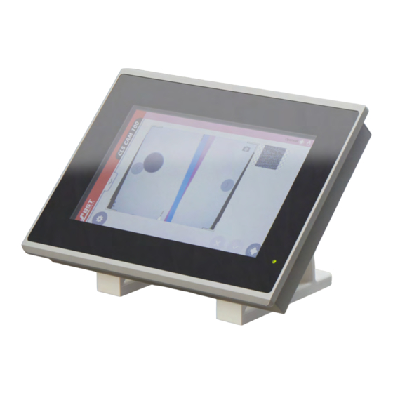
Design and function 3.3.3 Sensor Fig. 6: Components of the CLS CAM 100 sensor ① Touchscreen display Similar to the commander, during operation this graphic dis- play also shows all important information (live image, print features, edge positions, etc.), only in a reduced form. The system can also be operated in a rudimentary manner via this display. -
Page 23: Setpoint Position
The arrow buttons are available on the commander’s screen as well as on the sensor’s display. The setpoint position set will be shown in the display by a white triangle. Fig. 8: Setpoint position with displacement CLS CAM 100 – Object Sensor 23/220... -
Page 24: Measuring Range
The following informa- tion is displayed: Logged on user ■ Selected operating mode of the sensor ■ Operating state of the controller ■ State of the blocking of the controller ■ 24/220 CLS CAM 100 – Object Sensor... -
Page 25: Footer Menu
The quick menus can be opened and closed by clicking on the arrow buttons. Operating and display elements The CLS CAM 100 system is equipped with the following operating and display elements: Fig. 11: Operating and display elements CLS CAM 100 –... -
Page 26: Laser
70 dB(A). Accessories For accessories and the order address, see Accessories and Spare Parts, page 214. Name Plate All three components of the system are each provided with their own name plate: 26/220 CLS CAM 100 – Object Sensor... - Page 27 ⑥ Protection class Date of manufacture ⑦ (Calendar week/Year) ⑧ Cust.-Mat.-No. Customer article code ⑨ Operating voltage Hardware version (e.g. BD), ⑩ Firmware version (e.g. 1.2.14) ⑪ Type Type designation ⑫ Serial number CLS CAM 100 – Object Sensor 27/220...
-
Page 28: Technical Specifications
BST. Power supply Voltage 24 V⎓ ± 10 % (including ripple) Power consumption Protection class IP54 (when installed at the front Protection class on the display side) Certifications Certification Weight Weight 0.9 kg 28/220 CLS CAM 100 – Object Sensor... -
Page 29: Technical Specifications - Controller
24 V 2x M8 4-pin (plug/socket) incl. Connection CAN bus and 2-pin terminal in- ternal Input capacity 1320 uF Reverse polarity protection Protection class Protection class IP42 Certifications Certifications CE, RoHS CLS CAM 100 – Object Sensor 29/220... - Page 30 M8 (DIN IEC 61076) USB 3.1 connection (X20) USB 3.1 type A socket Ethernet connection (X30) M12-X-coded, 8-pin socket Ethernet connection (X40) M12-X-coded, 8-pin socket Dimensions (details in mm) Fig. 14: Dimensions - controller 30/220 CLS CAM 100 – Object Sensor...
-
Page 31: Technical Specifications - Sensor
103 mm x 147.5 mm x 231 mm Dimensions (with holder) (W x H x D) Measuring range (when installed correctly) Measuring range 60 mm x 45 mm Measuring distance (lower edge of sensor to material 30 mm web) CLS CAM 100 – Object Sensor 31/220... - Page 32 ~1 - ~20 µs Flashing rate >500 Hz Graphic display Type Capacitive touch colour display Active display area 58.6 mm x 46.5 mm Dimensions (details in mm) Fig. 15: Dimensions - sensor (with holder) 32/220 CLS CAM 100 – Object Sensor...
-
Page 33: Transport, Delivery And Storage
Transport, delivery and storage Transport, delivery and storage Transport The sensor of the CLS CAM 100 system is categorised as an optical instrument. It must be treated with appropriate care. NOTICE Damage to the sensor lens from careless handling! Soiling or scratches to the lens. - Page 34 Transport, delivery and storage Ambient conditions Permissible values Storage temperature -10 ... +70°C (+14 ... +158 °F) Humidity 5 ... 90 %, non-condensing 34/220 CLS CAM 100 – Object Sensor...
-
Page 35: Assembly
Cordon-off the work area in order to prevent access by unau- ► thorized persons (e.g. by setting up barriers). Make sure that all parts of the machine where the BST com- ► ponents have to be installed have a sufficient load bearing ca- pacity. -
Page 36: Selecting The Installation Location
Do not deactivate or remove any protection and safety equip- ► ment belonging to the machine. If the protection and safety equipment has to be removed for the installation of the BST components, these must be re-installed immediately after completing the installation work. -
Page 37: Space Requirement
■ must not be exceeded Space requirement Please obtain the dimensions of the CLS CAM 100 components from chapter Technical specifications, page 28. The components of the sensor must be easily accessible for all work to be carried out during the entire life cycle (see table). -
Page 38: Controller Assembly
You must ensure that the com- mander is not fitted close to high-voltage components or power lines when installed in an operator panel or a control station. Al- ways maintain a minimum clearance of 100 mm! 38/220 CLS CAM 100 – Object Sensor... - Page 39 NOTICE Note on the installation depth of the commander Observe an installation depth of the commander of at least 120 mm (see figure) Min. installation depth Fig. 19: Installation depth CLS CAM 100 – Object Sensor 39/220...
- Page 40 Fig. 21: Attaching the fixing clips to the commander 5. Tighten the screws ② of the fixing clips ① such that the tight fit of the commander ③ is ensured (see the following figure). 40/220 CLS CAM 100 – Object Sensor...
-
Page 41: Sensor Assembly
② is used for assembly of an optional light- ing for the sensor). Fig. 23: Assembly thread of the sensor 2. Fit the sensor the desired position. For this purpose, use the screw kit included in the scope of delivery. CLS CAM 100 – Object Sensor 41/220... -
Page 42: Sensor Alignment
④ and to the sensing roller ②. Fig. 24: Sensor alignment ① Sensor ② Sensing roller ③ Measuring range ④ Material web 2. Check if the sensor is aligned parallel to the material web (see the following figure). 42/220 CLS CAM 100 – Object Sensor... - Page 43 1. Slide the alignment tool (see position 2 in the figure below) from the front onto the sensor’s measurement window (see position 1 in the following figure). Fig. 26: Slide the alignment tool onto the sensor CLS CAM 100 – Object Sensor 43/220...
-
Page 44: Sensor Holder (Optional)
Sensor holder (optional) An optional holder is available for the sensor (see the following figure). This can be fitted on the sensor using the screw kit in- cluded in the scope of delivery. 44/220 CLS CAM 100 – Object Sensor... -
Page 45: Manual Adjustment (Optional)
The sensor can be fitted on the manual adjust- ment using the screw kit included in the scope of delivery. Fig. 29: Manual adjustment for the sensor (optional) ① Manual adjustment (optional) ② Sensor ③ Measuring range CLS CAM 100 – Object Sensor 45/220... -
Page 46: Bright Field Lighting (Optional)
1. Mount the bright field lighting on the sensor with 4 fixing screws as shown in the figure. 2. Connect the connection cable of the bright field lighting to the connection provided on the head of the sensor as shown in the figure. 46/220 CLS CAM 100 – Object Sensor... -
Page 47: Electrical Connection
Before connecting, make sure that the mains voltage corres- ► ponds with the details specified on the nameplate of the com- ponents. Select the correct terminals and polarity when connecting the ► power supply. CLS CAM 100 – Object Sensor 47/220... -
Page 48: Cable Routing
Fig. 31: Separate routing of signal and supply cables ➀ Cable duct ➂ Supply cable ➁ Signal cable Establish cable connections between the components accord- ► ing to the connecting diagram. 48/220 CLS CAM 100 – Object Sensor... -
Page 49: Ensuring Equipotential Bonding
Remove the paint coating in the contact area. ► Through hole Threaded hole Fig. 32: Use of fan type washers ① ② Screw ③ Fan type washer ④ Washer ⑤ Earthing cable CLS CAM 100 – Object Sensor 49/220... -
Page 50: Connections
) used for this purpose must have a ring cable lug on the side of the controller connection. Connections 7.4.1 Commander connections 7.4.1.1 Overview The following connections are located on the underside of the commander housing: Fig. 34: Connections of the commander 50/220 CLS CAM 100 – Object Sensor... - Page 51 + power supply commander 7.4.1.3 Ethernet The commander is connected to the Ethernet interface of the con- troller using an Ethernet network cable. View of the socket from outside Ethernet Fig. 36: Ethernet interface contact assignment CLS CAM 100 – Object Sensor 51/220...
-
Page 52: Controller Connections
The following connections are located on the front of the control- ler housing: For the purpose of better visibility, the tension relief for the sensor connection is not fitted in the following figure. Fig. 38: Controller connections 52/220 CLS CAM 100 – Object Sensor... - Page 53 Proceed as follows when connecting the sensor cable: 1. Insert the sensor cable ② into the controller sensor connec- tion. 2. Secure the sensor cable with the tension relief ①. 3. Then check the correct seating of the cable. CLS CAM 100 – Object Sensor 53/220...
- Page 54 IEC 61076-2-109, 8-pin) of the controller using an Ethernet network cable. 7.4.2.4 X100 - CAN bus (plug) The BST controller (ekr 500 digital Unit Touch, ekr CON 100, ekr CON 600) is connected to the controller via a 4-pin M8 micro style connector.
-
Page 55: Sensor Connections
Controller connection (image Data ently connected signal) with the sensor ex- factory. 7.4.3.2 X100 - control connection (plug) The sensor is connected to the controller via a 4-pin M8 micro- style connector. CLS CAM 100 – Object Sensor 55/220... -
Page 56: Establishing The Cable Connections
Establish the cable connections according to the figure. ► Sensor Controller Commander Control cable Data cable Equipotential bonding cable Ethernet cable CAN bus cable 24V cable voltage supply ekr 500 digitalUnit Touch ekr CON 600 Fig. 42: Cable connections standard application 56/220 CLS CAM 100 – Object Sensor... -
Page 57: Commissioning
Commissioning Safety Instructions WARNING Danger of death and material damage caused by incorrect com- missioning! Have the commissioning carried out by BST service personnel or ► authorized personnel only. DANGER Danger of death caused by the machine starting up! Parts of your body could be crushed, cut, drawn in or hit. -
Page 58: Requirements
8.3.3 Controller with EMS 23 actuator and Drive Module 160 If the CLS CAM 100 sensor system is operated in conjunction with a controller (ekr 500 digital or ekr CON 600) and the EMS 23 actu- ator with Drive Module 160, then the following preparations and... - Page 59 ON (see the previous figure). 7. Switch the DIP switches 7 and 8 on DIP switch block S4 of the controller processor board to OFF (see the previous figure). CLS CAM 100 – Object Sensor 59/220...
-
Page 60: Touchscreen Operation
With the setup mode, you determine the print features according to which the control takes place. All of the parameters that are needed to set up the CLS CAM 100 system are included in the system menu. It has a hierarchical structure. - Page 61 (see the following fig- ures). Fig. 44: Alphanumeric input Fig. 45: Numeric input 2. Carry out the necessary inputs via the keypad displayed. 3. If necessary, confirm your input with the ENTER button. CLS CAM 100 – Object Sensor 61/220...
- Page 62 ENTER button. Here the function is carried out immediately after select- ing the list entry. Function keys Several functions and options can also be activated directly via function buttons. 62/220 CLS CAM 100 – Object Sensor...
-
Page 63: Carrying Out Commissioning (Step-By-Step Instructions)
1. In the main view, press the adjacent button to open the Sys- tem menu (see the following figure). Fig. 48: System menu 2. In the System menu, press the adjacent button to open the Commissioning menu (see the following figure). CLS CAM 100 – Object Sensor 63/220... - Page 64 This is the delivery state. If the commissioning steps have been completed successfully, the buttons are represented in green (see the following figure). Fig. 50: Commissioning menu – Commissioning carried out successfully 64/220 CLS CAM 100 – Object Sensor...
-
Page 65: Steps To Be Carried Out
Moreover, the machine speed can also be adapted after this setup process. More information can be found in the chapter Adjust- ment of the machine speed, page 83. In the following sections, the individual work steps are described in more detail. CLS CAM 100 – Object Sensor 65/220... -
Page 66: Camera Mounting
2. Then press the ENTER button (see adjacent icon) to accept the settings carried out for the system. ð Now the Camera mounting page is closed and the Commis- sioning menu opens (see the following figure). 66/220 CLS CAM 100 – Object Sensor... -
Page 67: Camera Calibration
Now the Camera mounting button is represented green. 8.6.4 Camera calibration To enable the CLS CAM 100 system to operate correctly in the unit of measurement of millimetres, the following three calibrations must first be carried out on the sensor: Camera calibration ■... - Page 68 Fig. 54: Calibration template: Chessboard pattern with a square size of 2 mm 1. For calibration of the sensor, use the supplied Calibration piece CLS CAM 100 as a calibration template. If lost, the calibration piece can be ordered under the article number 2MECH442567 from BST (see chapterOrder Address, page 214).
- Page 69 5. Now tap on the Commissioning menu button (see adjacent icon). The Commissioning menu opens. Fig. 56: Commissioning menu 6. Press the Camera calibration button (see adjacent icon). A prompt for positioning the calibration template appears. Fig. 57: Prompt for positioning the calibration template CLS CAM 100 – Object Sensor 69/220...
- Page 70 Now the automatic calibration starts (see adjacent icon). A live image of the sensor is displayed. Under the live image, a status bar provides information about the progress of the calibration. Fig. 58: Display window of the auto calibration 70/220 CLS CAM 100 – Object Sensor...
- Page 71 Lens calibration ok ■ Lens compensation ok ■ The calibration of the camera was successful. Fig. 60: Camera calibration successful After successful camera calibration, then the laser calibration is carried out (see the following figure). CLS CAM 100 – Object Sensor 71/220...
- Page 72 Press the ENTER button (see adjacent icon) to accept the values ► determined by the calibration for the system. The calibration window is closed again and the Commissioning menu opens (see the following figure). 72/220 CLS CAM 100 – Object Sensor...
- Page 73 CLS CAM 100 – Object Sensor 73/220...
- Page 74 Fig. 65: Laser calibration successful Press the ENTER button (see adjacent icon) to accept the values ► of the calibration determined for the system. The laser calibration window closes. The calibration process is now complete. 74/220 CLS CAM 100 – Object Sensor...
-
Page 75: Automatic White Balance
The window for the white balance opens and the white balan- cing starts automatically. If the automatic white balance was successful, this is displayed in the window by a green square (see the following figure). CLS CAM 100 – Object Sensor 75/220... -
Page 76: Guiding Direction And Setpoint Display
8.6.7 Guiding direction and setpoint display The controller connected to the CLS CAM 100 system allows many attachment situations for the sensor. To keep the requirements on the setup of the controller as low as possible and to match the... - Page 77 Then repeat the previous step. Adjust the measured value of the side position to the guiding dir- ection: 1. The controller is in Manual controlling mode. Adjust the set po- sition by 1 mm. CLS CAM 100 – Object Sensor 77/220...
- Page 78 Set the acting direction of the arrow buttons for the remote con- trol of the setpoint: If the arrow buttons ① for the remote control of the setpoint (see the following figure) act in the wrong direction, the acting dir- ection can be changed. 78/220 CLS CAM 100 – Object Sensor...
-
Page 79: Web Angle Calibration
This error may be in the range of a few tenths, depending on the rota- tion. CLS CAM 100 – Object Sensor 79/220... - Page 80 If, on the other hand, the web angle calibration has failed, this is indicated by a red square (see the following figure). Now, the parameters camera angle and camera angle variation are not provided with values. 80/220 CLS CAM 100 – Object Sensor...
- Page 81 1. Press on the adjacent button. The following menu opens (see the following figure): Fig. 76: Manual correction of the rotation of the sensor head 2. Wipe away the satin finish over a suitable print feature using your finger (see the following figure). CLS CAM 100 – Object Sensor 81/220...
- Page 82 7. Then press the ENTER button (see adjacent icon) to accept the entered values in the system. ð You are now taken back to the Commissioning menu (see the following figure). 82/220 CLS CAM 100 – Object Sensor...
-
Page 83: Adjustment Of The Machine Speed
Fig. 80: System menu 2. Press the arrow icon (see adjacent icon) to the right next to the Machine menu entry. The menu screen for setting the machine speed opens (see the following figure). CLS CAM 100 – Object Sensor 83/220... - Page 84 Maximal web track- will be reached during production mode ing speed here. After finishing your entry, press the HOME button (see adja- ► cent icon). ð You are now taken back to the main screen. 84/220 CLS CAM 100 – Object Sensor...
-
Page 85: Operation
Damage to the touchscreen due to faulty operation! Use of sharp, strong or coarse objects (e.g. pens, gloves) may dam- age the surface of the touchscreen. Touch the touchscreen only using bare fingers or a special input ► pen (touchpen). CLS CAM 100 – Object Sensor 85/220... -
Page 86: Starting The System
Switch on the power supply to start the system. ► After switching on the power supply, the start program (boot loader) loads the operating system of the CLS CAM 100 system. This process should take approx. 5 seconds. Fig. 83: CLS CAM 100 start screen Then the start screen appears in the display for approx. -
Page 87: Setting The User Level
Fig. 85: General operating display Setting the user level The functional scope and setting options of the CLS CAM 100 sys- tem are defined by the selected user level. After starting the system, the operator user level is active by de- fault. - Page 88 ■ Complete operation of the sys- ■ tem is possible. maintenance main123 Can fully view and change the ■ system configuration. Can carry out firmware updates. ■ developer Access only for developers. ■ 88/220 CLS CAM 100 – Object Sensor...
-
Page 89: Changing User Level
Operation 9.3.1 Changing user level After starting the CLS CAM 100 system, the operator user level is automatically pre-set. In the following example, you should change to the maintenance user level. To do so, please proceed as follows: 1. In the status bar at the top right, tap on operator (see the fol- lowing figure). - Page 90 (see the follow- ing figure). Tap on the input field. Fig. 90: Input field for the password 5. Using the keypad now appearing, enter the password (see the following figure). 90/220 CLS CAM 100 – Object Sensor...
-
Page 91: Menu Navigation With The Commander
(see the following figure). Fig. 92: “maintenance” user level is active Menu navigation with the commander 9.4.1 Menu types The following 4 menu types are used on the CLS CAM 100 com- mander: Footer menu ■ Quick menus ■... - Page 92 Button: The state pressed is only active as long as the but- ton is pressed. The button cannot be selected, it does not react to contact. The symbol is greyed out. 92/220 CLS CAM 100 – Object Sensor...
- Page 93 Via the quick menus that are located on the left and right side of the screen, you can access additional functions, such as to change the operating mode. The quick menus can be opened and closed by clicking on the arrow buttons. CLS CAM 100 – Object Sensor 93/220...
- Page 94 Help button The system menu is used for the configuration and parametrisa- tion of the CLS CAM 100 system and can be accessed using a func- tion button on the main screen. The individual pages of the menu can be opened via tabs ①.
- Page 95 Fig. 98: QR code for online help This QR code enables you to obtain quick and direct access to the online documentation of the CLS CAM 100 via the internet. All that you need to open the online documentation is a smartphone or tablet with camera and internet access that has a QR code scanner software installed.
- Page 96 Fig. 99: Live View is active Now press the live button represented blue (see adjacent icon) ► again to deactivate the Live View function again. ð The small pop-up window closes and the live button turns dark grey. 96/220 CLS CAM 100 – Object Sensor...
-
Page 97: Path Information
Fig. 100: Menu structure Operating displays on the commander The screen in the display of the CLS CAM 100 commander is de- pendent on the mode in which the system will be operated. We differentiate between setup mode and Measuring mode. The menus can also be called up from either mode. -
Page 98: Setup Mode Display Window
This applies for the Art Guiding operating mode. In the Edge Guiding and Line Guiding operating modes, markers appear instead to indicate the selected edge or line. 98/220 CLS CAM 100 – Object Sensor... -
Page 99: Display Window In Measuring Mode
③ Limitation of the selected print feature. ④ Display of the selected print feature: The sensor always searches the material web for this feature. ⑤ Live image of the sensor measuring range. CLS CAM 100 – Object Sensor 99/220... -
Page 100: Status Bar
Moreover, the currently logged-in user is output in plain text. Icon Meaning Controller is in manual mode Controller is in automatic mode System is in centre position (SC mode) 100/220 CLS CAM 100 – Object Sensor... -
Page 101: Selecting The Operating Mode
1. Open the quick menu to select the operating mode by pressing the arrow button pointing to the right on the left side of the screen (see the following figure). Fig. 103: Opening the “Operating mode” quick menu CLS CAM 100 – Object Sensor 101/220... -
Page 102: Art Guiding With The Commander
Art Guiding with the commander To control the CLS CAM 100 system according to a desired print feature (Art guiding), either a new unique feature must first be created, or an existing unique feature must be loaded as a job. -
Page 103: Create New Art Guiding Unique Feature
To create a new Art Guiding unique feature, proceed as follows: Initial position: ›› The CLS CAM 100 system is located in the measuring mode and the live image of the sensor can be seen in the display (see the following figure). - Page 104 The part that has been swiped free is now displayed normally. The selected print feature is displayed via the image history with a small cross wire in the middle (see the following figure). 104/220 CLS CAM 100 – Object Sensor...
- Page 105 8. Switch the connected controller to AUTOMATIC operating mode. ð Now the system automatically controls to the middle of the selected print feature. The following figure shows a typical image of the CLS CAM 100 system in automatic mode. CLS CAM 100 – Object Sensor 105/220...
-
Page 106: Fine Adjustment Of The Art Guiding Unique Feature
Operation Fig. 110: CLS CAM 100 system in automatic mode 9.7.2 Fine adjustment of the Art Guiding unique feature If a print feature is selected as described in chapter Create new Art Guiding unique feature, page 103, by default the control is automatically carried out to the middle of this feature. - Page 107 1. To activate the function, please press the Eraser button in the pop-up window (see adjacent icon). The cross wire disappears and the eraser button is represented blue (see the following figure). Fig. 113: Clear the desired print feature by swiping CLS CAM 100 – Object Sensor 107/220...
- Page 108 (see adjacent icon). A frame with a cross wire now appears and the pipette button is represented in blue (see following figure). Fig. 115: Place the hole of the cross wire on the desired print feature 108/220 CLS CAM 100 – Object Sensor...
- Page 109 ð You return to the main screen. Now the sensor is back in measuring mode and control takes place according to the newly selected print feature. Fig. 117: Control takes place according to the newly selected print feature CLS CAM 100 – Object Sensor 109/220...
-
Page 110: Activate Continuous Measurement
A pop-up now opens at the bottom edge of the display. 3. Tap on the button in the pop-up on the left (see following fig- ure) to activate Continuous measurement. Fig. 119: Tap on the button to activate the “Continuous Measurement” 110/220 CLS CAM 100 – Object Sensor... - Page 111 The points recorded during the measurement will now be guided to the unique feature. Fig. 121: Measurement was successful Click on the ENTER button (see adjacent icon) to finally access ► the measurement mode. CLS CAM 100 – Object Sensor 111/220...
- Page 112 1. Adjust the threshold value for the detection by changing the value with the plus/minus buttons (see following figure). Fig. 123: Adjusting the threshold value 2. Repeat the measurement procedure under ‘Adjusting the threshold’ until you get a successful measurement result (green tick). 112/220 CLS CAM 100 – Object Sensor...
-
Page 113: Edge Guiding With The Commander
To create a new Edge Guiding unique feature, proceed as follows: Initial position: The CLS CAM 100 system is located in the setup mode and the ■ live image of the sensor can be seen in the display (see the fol- lowing figure). - Page 114 ð The system now automatically guides to the selected edge. If you would like to select a different edge at a later time, click ► on the opposite button to return to the setup mode for Edge Guiding. 114/220 CLS CAM 100 – Object Sensor...
-
Page 115: Fine Adjustment Of The Edge Guiding Unique Feature
(see following figure). The pop-up window shows that the system has detected another edge ② in addition to the se- lected edge ① (see line markers at the bottom of the image). CLS CAM 100 – Object Sensor 115/220... - Page 116 1. Correct the threshold value for edge detection continuously with the plus and minus button (see graphic opposite) until the new edge is detected. 116/220 CLS CAM 100 – Object Sensor...
-
Page 117: Line Guiding With The Commander
To create a new Line Guiding unique feature, proceed as follows: Initial position: The CLS CAM 100 system is located in the setup mode and the ■ live image of the sensor can be seen in the display (see the fol- lowing figure). - Page 118 (see following figure). The same edge markers (left edge ①, right edge ②) are also displayed in the live im- age, supplemented by quality values of the edges that are above the respective markers. Fig. 132: The line is selected 118/220 CLS CAM 100 – Object Sensor...
-
Page 119: Fine Adjustment Of The Line Guiding Unique Feature
Several lines have been swiped free and the system has selec- ■ ted the wrong line. The selection of the line should be corrected. ■ Correction of the line selection: Tap on the display of the selected line (see following figure). ► CLS CAM 100 – Object Sensor 119/220... - Page 120 1. Tap the selection button for the right edge of the line (see ad- jacent icon). The button turns light blue (see following figure). 2. Now tap on the image with your finger. A cross wire appears (see following figure). 120/220 CLS CAM 100 – Object Sensor...
- Page 121 A possible cause could be a threshold value for the detection of an edge that is set too high. CLS CAM 100 – Object Sensor 121/220...
-
Page 122: Jobs And Templates
You can only save a job in measuring mode. To save the currently active unicum, please proceed as follows. Open the Job menu by pressing the Job button in the footer ► menu in the main view (see adjacent icon). 122/220 CLS CAM 100 – Object Sensor... - Page 123 1. To save the job, click on the Save button (see adjacent icon). A pop-up and an input keyboard open (see the following fig- ure). A miniaturised representation of the unicum to be saved is displayed again on the left side of the pop-up. CLS CAM 100 – Object Sensor 123/220...
- Page 124 CON 600 con- troller. If the job selection should only be carried out via the CLS CAM 100 Commander, slot 0 can be selected for all jobs to be saved. Fig. 142: Confirm input of job name and slot 4.
-
Page 125: Loading The Unicum As A Job
An enlarged representation of the active job is displayed in the large tile on the right side of the screen. Fig. 144: Job menu with two saved jobs 2. Tap on the tile of the job you want to load. CLS CAM 100 – Object Sensor 125/220... -
Page 126: Deleting A Job
Fig. 146: Job menu with two saved jobs 2. Tap on the tile of the job that you want to delete (this is “Test- job 02” in the example shown here). Now the tile is represented highlighted blue. 126/220 CLS CAM 100 – Object Sensor... - Page 127 ð The deleting procedure is now completed and the tile of the job deleted is removed from the overview (see the following figure). Fig. 148: Deleting procedure completed Then press the Home button to return to the main view. ► CLS CAM 100 – Object Sensor 127/220...
-
Page 128: Exporting And Importing Jobs To Usb Mass Storage Device
Operation 9.10.4 Exporting and importing jobs to USB mass storage device Jobs stored in the CLS CAM 100 system can be exported to and imported again from a USB mass storage device. For example, jobs can be transferred from one CLS CAM 100 system to another. - Page 129 1. Click on the Export tab in the pop-up window (see adjacent icon). A list of the jobs saved in the CLS CAM 100 system appears (see following figure). 2. Click in the white square in front of the job you want to export (see following figure).
- Page 130 (see following figure). Fig. 153: Job “Testjob Line” was exported successfully Then click the Enter button (see adjacent icon) to return to the ► main screen. ð The export process is now complete. 130/220 CLS CAM 100 – Object Sensor...
- Page 131 3. Click on the button with the arrow pointing to the right (see ad- jacent icon) to start the import. ð After successful import, a green tick appears to the right of the job imported (see following figure). CLS CAM 100 – Object Sensor 131/220...
-
Page 132: Parameter Templates
(see adjacent icon). The Job menu opens (see the following figure). Fig. 157: Job menu 2. To open the selection menu for parameter templates, click on the tab with the template symbol (see adjacent icon). 132/220 CLS CAM 100 – Object Sensor... - Page 133 Edge be kept to a minimum in this case. Use, for example, when the color of the edge being scanned changes frequently or if the print in setup mode is uneven. CLS CAM 100 – Object Sensor 133/220...
-
Page 134: Global Settings
The selected template is now active. 9.11 Global settings The quick menu on the right edge of the display can be used to make global settings for the CLS CAM 100 system. The following settings are available: Button... - Page 135 A pop-up window with a slide bar opens. The threshold value is shown in %. Fig. 161: Quick menu opened - select threshold value 3. Move your finger over the slide bar and set the desired threshold value (see the following figure). CLS CAM 100 – Object Sensor 135/220...
- Page 136 9.11.2 Setting the brightness of the sensor lighting The sensor of the CLS CAM 100 system can be easily adjusted to the respective lighting conditions of the operating environment. To do so, the intensity of the LED lighting of the sensor can be set.
- Page 137 You can cancel the process at any time by pressing the Es- cape button: 9.11.3 Lighting selection The sensor of the CLS CAM 100 system has three different lighting profiles. The following profiles are available: Lighting profile Properties / Function...
- Page 138 Operation Lighting profile Properties / Function This profile activates the stand- DefaultIllumination ard lighting of the CLS CAM 100 system. This is a lighting profile with a weaker illumination, which is LowLightDarkfieldIllumination used at high web speeds of up to 1,200 m/min to avoid the cre- ation of streaks in the image.
- Page 139 The selected lighting profile is now active. 9.11.4 Setting the Region of Interest In some cases it may be necessary to set the Region of Interest, thus the area to be monitored by the sensor, more precisely. CLS CAM 100 – Object Sensor 139/220...
- Page 140 The sensor would now start jumping back and forth between the two recognized features. It would not be possible to clearly guide to the middle column. Fig. 171: Region of Interest set too large 140/220 CLS CAM 100 – Object Sensor...
- Page 141 3. Move your finger over the slider and set the desired width of the Region of Interest (see following figure). The changed width is indicated by the dashed lines of the Re- gion of Interest outer limits. CLS CAM 100 – Object Sensor 141/220...
- Page 142 The following figure now shows the ideally set Region of Interest (shown slightly satined in the following figure) with the desired print feature. Fig. 175: Region of Interest set correctly 142/220 CLS CAM 100 – Object Sensor...
-
Page 143: Adjustment Of The Setpoint Position
LEFT ④ or RIGHT ⑤ arrow button. 9.13 Using the direct operation on the sensor The sensor of the CLS CAM 100 system is equipped with a small touchscreen display. This display can be used to operate the basic functions of the system directly on the sensor without the com- mander. -
Page 144: Structure Of The Sensor Display
“Art Guiding”. The display of points ②, ③ and ⑪ may vary slightly depending on the selected op- erating mode. The following table provides information on the different forms of display of points ②, ③ and ⑪. 144/220 CLS CAM 100 – Object Sensor... - Page 145 The system is in measuring mode. There is a pending fault. The print feature has either not been detected or poorly detected. The system is in setup mode. The system is in measuring mode and the controller is in manual mode. CLS CAM 100 – Object Sensor 145/220...
-
Page 146: Selecting The Operating Mode Of The Sensor
Function button Meaning / function Operating mode switching button: This button can be used to switch the operating mode of the controller connected to the CLS CAM 100 sys- tem between AUTOMATIC and MANUAL. Art Guiding setup button: Pressing this button switches the sensor into setup mode. - Page 147 Fig. 179: Press the operating mode selection button In the example shown here, the operating mode has been switched from Edge Guiding to Line Guiding (see following figure). CLS CAM 100 – Object Sensor 147/220...
-
Page 148: Switching The Operating Mode Of The Controller
(see adjacent icon) in the page menu to switch to MANUAL mode. The operating mode symbol in the status bar changes to MANUAL and the operating mode button now shows the AUTOMATIC symbol (see the following figure). 148/220 CLS CAM 100 – Object Sensor... - Page 149 To select a print feature to be used for guiding, proceed as fol- lows. 1. Press the setup button (see adjacent icon). Now the sensor is in setup mode (see the following figure). CLS CAM 100 – Object Sensor 149/220...
- Page 150 You return to the measuring mode , and guiding now takes place according to the middle of the selected print feature. 4. If, however, you want to discard the selection, press the DE- LETE button (see adjacent icon). 150/220 CLS CAM 100 – Object Sensor...
-
Page 151: Selecting An Edge For Edge Guiding
Now the sensor is in setup mode (see the following figure). Fig. 185: Selecting an edge in setup mode 2. Tap on the desired edge with your finger. A marker now appears on the selected edge (see following fig- ure). CLS CAM 100 – Object Sensor 151/220... -
Page 152: Selecting A Line For Line Guiding
9.13.6 Selecting a line for Line Guiding To select a line to be used for guiding, proceed as follows. 1. Press the setup button (see adjacent icon). Now the sensor is in setup mode (see the following figure). 152/220 CLS CAM 100 – Object Sensor... - Page 153 You return to the measuring mode and guiding now takes place according to the selected line. If, however, you want to discard the selection, press the DE- ► LETE button (see adjacent icon). CLS CAM 100 – Object Sensor 153/220...
-
Page 154: Adjustment Of The Setpoint Position
During the displacement of the setpoint position, the distance is faded in as plain text at the bottom edge of the screen. The dis- tance can be a positive or negative value. To adjust the setpoint position, proceed as follows. 154/220 CLS CAM 100 – Object Sensor... -
Page 155: Traversing The Guiding Device
2. However, first switch the connected controller into MANUAL operating mode. 9.14 Controlling the system via an external browser It is possible to control the CLS CAM 100 system without a connec- ted commander via an external browser. The following require- ments must be met for this purpose: An external computer must be connected to the second Ether- ■... - Page 156 The full range of functions of the commander is now available in the browser. Only the update function for the firmware is not available. The representation size always adapts to the size of the browser window. 156/220 CLS CAM 100 – Object Sensor...
-
Page 157: System Menu Of The Commander
Only the Help button is present on all menu pages. ⑤ Arrow button: If another menu level is present behind a menu entry, this can be opened by tapping on the arrow button. CLS CAM 100 – Object Sensor 157/220... -
Page 158: Menu Structure
Log on with the “maintenance” user level. More in- ► formation on changing the user level can be found in chapter Setting the user level, page 87. 158/220 CLS CAM 100 – Object Sensor... -
Page 159: Menu Page: System Parameter
System menu of the commander 10.3 Menu page: System Parameter The menu page System parameter is sub-divided as follows: Fig. 193: System menu - System parameter CLS CAM 100 – Object Sensor 159/220... -
Page 160: Ekr Remote Settings
■ Sensor ■ A description of the sub-pages will be carried out in the following sections. 10.3.1 ekr Remote Settings \ system parameter \ ekr remote settings Fig. 195: Sub-screen - Ekr Remote Settings 160/220 CLS CAM 100 – Object Sensor... - Page 161 Switch on the Live View via the “live” button while you are making settings. In this way, you can see the effect of the settings directly. 10.3.2 Guiding \ system parameter \ guiding Fig. 196: Sub-screen - Guiding CLS CAM 100 – Object Sensor 161/220...
- Page 162 KeepValue: When changing from setup ■ to measuring mode, the setpoint entered is retained. SetupPosition: When changing from ■ setup to measuring mode, the current position of the unique feature is taken over as setpoint. 162/220 CLS CAM 100 – Object Sensor...
- Page 163 You can set the machine speed for setup and production mode here. Further information on this procedure can be found in chapter Adjustment of the machine speed, page 83. 10.3.4 Mounting parameter \ system parameter \ mounting parameter Fig. 198: Sub-page - Mounting parameter CLS CAM 100 – Object Sensor 163/220...
-
Page 164: Sensor
\ system parameter \ Sensor Fig. 199: Sub-screen - Sensor The sensor menu screen contains the following sub-screens which can be opened by clicking on the adjacent arrow icon: Calibration ■ Camera ■ Display ■ 164/220 CLS CAM 100 – Object Sensor... - Page 165 The values of the parameters represented here have been meas- ured during commissioning of the CLS CAM 100 system and can be adjusted if required. The following parameters are displayed: Parameter...
- Page 166 \ system parameter \ sensor \ camera Fig. 201: Menu screen - Camera This menu screen shows the measuring surface used by the sensor in pixels. Sub-screen “Display” \ system parameter \ sensor \ display Fig. 202: Menu screen - Display 166/220 CLS CAM 100 – Object Sensor...
-
Page 167: Menu Page: Parameter
(in the previous figure the parameter is deactivated). 10.4 Menu page: Parameter The Parameter menu screen is sub-divided as follows: Fig. 203: System menu – Parameter CLS CAM 100 – Object Sensor 167/220... -
Page 168: Art Guiding
The description of the sub-screens is carried out in the following sections. 10.4.1 Art guiding \ parameter \ art guiding Fig. 205: Sub-screen - Art Guiding 168/220 CLS CAM 100 – Object Sensor... - Page 169 Set the inside spacing of the Region of In- ► terest here. Template Setup No unique feature can be selected in the Padding [mm] area of the inner spacing (see red frame in the following figure). CLS CAM 100 – Object Sensor 169/220...
- Page 170 In this way, you can see the effect of the settings directly. 10.4.2 General tracking \ parameter \ general tracking Fig. 207: Sub-page - General tracking Set the tolerance limit for the splice offset here. ► 170/220 CLS CAM 100 – Object Sensor...
- Page 171 Note: When carrying out the settings, switch on the Live View using the “live” button. You can inspect the effect of the settings directly. CLS CAM 100 – Object Sensor 171/220...
- Page 172 Fig. 210: Sub-page - Image enhancement 2. Reduce the image noise with the Noise reduction parameter. 3. Readjust the image sharpness with Sharpness. 4. For setting the values, use the Plus and Minus buttons . 172/220 CLS CAM 100 – Object Sensor...
- Page 173 Set the low-pass filter for edge detection ► Low pass filter here. The higher the value, the stronger the effect of the filter. CLS CAM 100 – Object Sensor 173/220...
- Page 174 Tracking sub-screen. Tracking More information about the Tracking sub- screen can be found in Tracking, page 174. 10.4.5.1 Tracking \ parameter \ line & edge guiding \ tracking Fig. 212: Sub-screen - Tracking 174/220 CLS CAM 100 – Object Sensor...
- Page 175 The higher the value set here, the less the older values are taken into account. CLS CAM 100 – Object Sensor 175/220...
- Page 176 The following figure shows the test points (① and ②) and the adjustable tolerance ranges (③ and ④) in the graphical repres- entation of a contrast transition. Fig. 214: Test points of a contrast transition 176/220 CLS CAM 100 – Object Sensor...
- Page 177 Setting options: NoCheck: The parameter is deactivated ■ EndCheck: ② ■ FullCheck: ①, ② ■ StartCheck: ① ■ Select the desired setting options by tap- ► ping on them. CLS CAM 100 – Object Sensor 177/220...
- Page 178 (①, ②, ③, ④), the adjustable tolerance ranges (⑤, ⑥) and the range of the line width (⑦). Fig. 216: Test points of the contrast transitions 178/220 CLS CAM 100 – Object Sensor...
- Page 179 ■ StartEndCheck: ①, ④ ■ Select the desired setting options by tap- ► ping on them. Width Tolerance Enter a tolerance value for the line width ► [mm] ⑦ to be detected here. CLS CAM 100 – Object Sensor 179/220...
-
Page 180: Menu Page: Measurement
Repeat length The repeat length is displayed here. The current speed of the material Web speed web is displayed here. Press the HOME button (see adjacent icon) to return to the ► main view. 180/220 CLS CAM 100 – Object Sensor... -
Page 181: Menu Page: Service
Fig. 219: System menu – Service Fig. 220: Menu page - Service The menu page contains the entry Infos. The following sub-pages can be found under this entry: Camera ■ Controller ■ Image processing statistic ■ CLS CAM 100 – Object Sensor 181/220... - Page 182 To access the menu entries that are found a little further down in the list, you must scroll downwards on the touchscreen by swiping. The following values and parameters are shown on this menu page: 182/220 CLS CAM 100 – Object Sensor...
- Page 183 CPU 1 temperature [°C] 1 in the controller. Shows the current temperature of the GPU temperature [°C] GPU in the controller. Shows the current temperature of CPU CPU 2 temperature [°C] 2 in the controller. CLS CAM 100 – Object Sensor 183/220...
- Page 184 Maximum latency when processing Max Latency an image Max Process Time Maximum processing time of an image Minimum latency when processing an Min Latency image Minimum processing time of an im- Min Process Time 184/220 CLS CAM 100 – Object Sensor...
-
Page 185: Menu Page: Network Settings
If the network connection is interrupted, the display first changes to the OPC-UA Connection Screen (see following figure). Fig. 227: Display changes to the OPC-UA Connection Screen CLS CAM 100 – Object Sensor 185/220... - Page 186 2. Then press the ENTER button (see graphic opposite) to confirm your entry. 3. The network connection is now established. As soon as it is act- ive, the green chain symbol appears next to the sensor icon. 186/220 CLS CAM 100 – Object Sensor...
-
Page 187: Resetting The Network Settings To Default Values
ð The network settings are now reset to the default values. 10.7.3 Configuration of the second Ethernet connection The controller of the CLS CAM 100 system has two Ethernet con- nections. The first connection (Ethernet0) is used by the com- mander. - Page 188 3. Now enter the connection data for the second Ethernet con- nection. When entering the IP addresses, make sure that you also enter the dots. The completed input fields should look similar to the following figure. 188/220 CLS CAM 100 – Object Sensor...
-
Page 189: Configuration Of Additional Commanders
ð The configuration of the second Ethernet connection is now complete. 10.7.4 Configuration of additional commanders If additional commanders are to be operated on the CLS CAM 100 system in addition to the existing one, their network settings can be configured here. Up to four additional commanders can be connected to the system via a network switch. -
Page 190: Menu Page: Info & Update
It is also possible to manually re- start the commander, the Controller and the Sensor from here. Furthermore, this screen provides technical information on all components of the CLS CAM 100 system. The following informa- tion is available: Components... - Page 191 Press this button to restart the sensor. Please observe the following: To access the menu entries that are found further down in the list on the menu screen, you must scroll down- wards by swiping. CLS CAM 100 – Object Sensor 191/220...
-
Page 192: Capture Images" Function
1. Press the Capture Images button (see adjacent icon) in the Info & Update menu. The Capture Images pop-up window opens (see following fig- ure). 192/220 CLS CAM 100 – Object Sensor... - Page 193 Fig. 239: Select recording format from the drop-down menu 3. Enter a file name for the recording file in the input field next to the entry File name (see following figure). CLS CAM 100 – Object Sensor 193/220...
- Page 194 “ESCAPE” button (see adjacent icon). Fig. 241: The recording is running The recording is finished as soon as the ENTER button (see adja- cent icon) appears on the right-hand side of the pop-up window. 194/220 CLS CAM 100 – Object Sensor...
-
Page 195: Menu Page: System Log
Fig. 243: System Log Tab with different entries Function buttons are located to the left next to the list of system messages. Their function will be described in more detail in the following chapters. CLS CAM 100 – Object Sensor 195/220... - Page 196 Fig. 244: Configuring the reception of log messages The following configuration options are available here: Parameter Meaning/function In the drop-down menu, select which log type should be shown. You can select between the fol- Log level lowing types: Failure ■ 196/220 CLS CAM 100 – Object Sensor...
- Page 197 Now it is shown with a dark blue background (see the following figure). Fig. 245: Message selected 2. Now press the Magnifying glass button. A pop-up window opens with an enlarged representation of the message (see the following figure). CLS CAM 100 – Object Sensor 197/220...
- Page 198 3. Press the Enter button to close the pop-up window (see adja- cent graphic). Calling up the help function Press the adjacent button to call up the help function of the sys- tem. 198/220 CLS CAM 100 – Object Sensor...
-
Page 199: Performing A Firmware Update
For the firmware update, you need a USB memory stick with a 2 GB storage capacity. The memory stick must be formatted with the file system FAT 32 (Windows standard). The update file for the CLS CAM 100 commander has the following format: CLS-CAM-100-Commander_update_re- ■... -
Page 200: Performing An Update
Proceed as follows to perform a firmware update of the com- mander: In the Info & Update menu, tap on the button to open the up- ► date dialogue for the commander (see position ③ in the fol- lowing figure). 200/220 CLS CAM 100 – Object Sensor... - Page 201 2. If you need any help with this procedure, press the Help button (see position ② in the previous figure). A help page opens that shows you where to find the USB port (see the following figure). CLS CAM 100 – Object Sensor 201/220...
- Page 202 (see position ② in the fol- lowing figure). Fig. 252: Stick was recognised - file dialogue active 1. Open the file dialogue by tapping on the adjacent button. The file dialogue opens (see the following figure). 202/220 CLS CAM 100 – Object Sensor...
- Page 203 6. Wait until the update process is finished. You can follow the progress of the update by means of a pro- gress bar and a list in which the processed steps are displayed (see the following figure). CLS CAM 100 – Object Sensor 203/220...
- Page 204 In this case, briefly switch the commander off and back on again. Now the commander should restart normally. 2. Then check the version of the firmware in the Info menu. 204/220 CLS CAM 100 – Object Sensor...
-
Page 205: Performing A Firmware Update For The Controller
2. If you need any help with this procedure, press the Help button (see position ② in the previous figure). A help page opens that shows you where to find the USB port (see the following figure). CLS CAM 100 – Object Sensor 205/220... - Page 206 (see position ② in the fol- lowing figure). Fig. 260: Stick was recognised - file dialogue active 1. Open the file dialogue by tapping on the adjacent button. The file dialogue opens (see the following figure). 206/220 CLS CAM 100 – Object Sensor...
- Page 207 6. Wait until the update process is finished. You can follow the progress of the update by means of a pro- gress bar and a list in which the processed steps are displayed (see the following figure). CLS CAM 100 – Object Sensor 207/220...
- Page 208 Fig. 264: Commander connects with the controller After a short period the connection is established and the system displays the familiar user environment again on the commander. Then check the version of the firmware in the Info menu. ► 208/220 CLS CAM 100 – Object Sensor...
-
Page 209: Troubleshooting/Faq
A similar print feature has been same for the software. threshold or determine a detected in addition to the de- larger and clearer area for Detection threshold set too ■ sired print feature. the print feature. low. CLS CAM 100 – Object Sensor 209/220... -
Page 210: Maintenance And Cleaning
/ cleaning! Have the maintenance and cleaning carried out only by quali- ► fied personnel that have been instructed by BST service person- nel or authorized personnel. Carry out the maintenance and cleaning as described in the fol- ►... -
Page 211: General Information
Only then can the relevant work be undertaken. The maintenance or cleaning intervals depend on the environ- mental conditions at the installation site. If you are processing very dusty materials the maintenance/cleaning intervals must be reduced accordingly. CLS CAM 100 – Object Sensor 211/220... -
Page 212: Maintenance Table
The lens of the sensor must be cleaned regularly in order to obtain optimum control results. Spotted or homogeneous dirtying of the lenses can result in wrong readings. This is why the sensor lens 212/220 CLS CAM 100 – Object Sensor... -
Page 213: Cleaning The Touchscreen Display
Make sure that no dirt particles or similar are rubbed over the ► cover of the lighting. Clean the cover of the lighting with great care using a moist, ► completely clean and soft cloth (e.g. glasses wipe). Do not use any cleaning agents! CLS CAM 100 – Object Sensor 213/220... -
Page 214: Accessories And Spare Parts
Accessories and Spare Parts Accessories and Spare Parts 14.1 Order Address BST GmbH Remusweg 1 D-33729 Bielefeld Germany Tel.: +49 (0) 521 400 70 767 E-Mail: service@bst.group http: www.bst.group 214/220 CLS CAM 100 – Object Sensor... -
Page 215: Customer Services
■ Serial number and date of manufacture (see name plate) ■ Customer Services Address BST GmbH Service Remusweg 1 D-33729 Bielefeld Germany Tel.: +49 (0) 521 400 70 767 E-Mail: service@bst.group http: www.bst.group CLS CAM 100 – Object Sensor 215/220... -
Page 216: Shutting Down And Disposal
Also note the legal regulations as well as local recycling guidelines for this purpose. Returning the system to BST GmbH is always possible. About this and for all other queries, please contact BST Customer Services, page 215. -
Page 217: Index
Selected print feature ........ 98 Configure ............. 187 Setup mode button........ 100 Configuring additional commanders ... 189 Status bar .......... 98, 99 Second connection ........ 187 Switching controller operating mode .. 100 Export jobs ........... 128 CLS CAM 100 – Object Sensor 217/220... - Page 218 Instructed personnel ........ 14 Operating company Duties............. 15 Operating displays Commander ........... 97 Operating manual Delete............ 126 Distribution ............ 7 Load ............. 125 Latest version........... 8 Storage............. 7 Operating mode Select ............ 101 Laser............ 22, 26 218/220 CLS CAM 100 – Object Sensor...
- Page 219 Sensor calibration ........... 67 Ekr Remote Settings........ 161 Calibration template ........ 68 Guiding............ 162 Mounting parameter ........ 164 Sensor display Sensor ............ 164 Change controlling mode button.... 144 Guide marker of the print feature .... 144 CLS CAM 100 – Object Sensor 219/220...
- Page 220 Fine adjustment ........... 106 Unpacking the delivery ........ 33 USB mass storage device ...... 128 Non-intended.......... 10 User level ............ 87 Change ............ 89 Using the system .......... 19 Virus scanner .......... 10 Warranty terms .......... 17 Web angle calibration........ 79 White balance.......... 75 220/220 CLS CAM 100 – Object Sensor...
Need help?
Do you have a question about the CLS CAM 100 and is the answer not in the manual?
Questions and answers