Table of Contents
Advertisement
Quick Links
R8HE / PPG3HE SERIES
INSTALLATION INSTRUCTIONS
GROUND MOUNT - SINGLE PACKAGE GAS HEATING / ELECTRIC COOLING
FIRE OR EXPLOSION HAZARD
• Failure to follow safety warnings exactly
could result in serious injury or property
damage.
• Installation and service must be performed
by a qualified installer, service agency or
the gas supplier.
• Do not store or use gasoline or other
flammable vapors and liquids in the vicinity
of this or any other appliance.
WHAT TO DO IF YOU SMELL GAS
• Do not try to light any appliance.
• Do not touch any electrical switch; do not
use any phone in your building.
• Leave the building immediately.
• Immediately call your gas supplier from a
neighbors phone. Follow the gas suppliers
instructions.
• If you cannot reach your gas supplier, call
the fire department.
DO NOT DESTROY. PLEASE READ CAREFULLY & KEEP IN A SAFE PLACE FOR FUTURE REFERENCE.
WARNING / AVERTISSEMENT
RISQUE D'INCENDIE OU D' EXPLOSION
• Le non-respect des avertissements de sécurité
pourrait entraîner des blessures graves, la mort
ou des dommages matériels.
• L'installation et l'entretien doivent être effectués
par un installateur qualifié, un organisme de
service ou le fournisseur de gazstaller, service
agency or the gas supplier.
• Ne pas entreposer ni utiliser de l'essence ni
d'autres vapeurs ou liquides inflammables dans le
voisinage de cet appareil,ni de tout autre appareil.
QUE FAIRE S'IL Y A UNE ODEUR DE GAZ
• Ne pas tenter d'allumer aucun appareil.
• Ne toucher à aucun interrupteur électrique;
n'utiliser aucun téléphone dans le bâtiment.
• Évacuer l'immeuble immédiatement.
• Appeler immédiatement le fournisseur de gaz en
employant le téléphone d'un voisin. Respecter à
la lettre les instructions du fournisseur de gaz.
• Si personne ne répond, appeler le service des
incendies.
14 SEER / 95% AFUE
Advertisement
Table of Contents

Subscribe to Our Youtube Channel
Related Manuals for Nordyne R8HE Series


Summary of Contents for Nordyne R8HE Series
- Page 1 R8HE / PPG3HE SERIES 14 SEER / 95% AFUE INSTALLATION INSTRUCTIONS GROUND MOUNT - SINGLE PACKAGE GAS HEATING / ELECTRIC COOLING WARNING / AVERTISSEMENT RISQUE D’INCENDIE OU D’ EXPLOSION FIRE OR EXPLOSION HAZARD • Le non-respect des avertissements de sécurité •...
-
Page 2: Table Of Contents
TABLE OF CONTENTS OPERATING SEQUENCE ......... 19 IMPORTANT SAFETY INFORMATION ..... 3 Heating Mode ...............19 REQUIREMENTS & CODES ........4 Thaw Cycle Start Up / Shutdown .........20 GENERAL INFORMATION........5 Blocked Vent / Condensate Disposal Shut Down ..20 Before you install this unit ..........5 Cooling Mode - Single Stage Operation ......20 Locating the Equipment ..........5 De-Humidification Control ..........20... -
Page 3: Important Safety Information
IMPORTANT SAFETY INFORMATION WARNING: Please read all instructions before servicing this equipment. Pay attention to all safety warnings and any other special PROPOSITION 65 WARNING: This product notes highlighted in the manual. Safety markings are contains fiberglass insulation. Disturbing the used frequently throughout this manual to designate a insulation of this product during installation, degree or level of seriousness and should not be ignored. -
Page 4: Requirements & Codes
• The installer should become familiar with the units wiring • Use only with the type of gas approved for this unit. diagram before making any electrical connections to the Refer to the unit rating plate. • Provide adequate combustion and ventilation air to the unit. -
Page 5: General Information
Locating the Equipment GENERAL INFORMATION • Select a solid, level position, preferably on a concrete This Single Package Gas Heating / Electric Cooling Unit is slab, slightly above the grade level, and parallel to the designed only for ground level slab installations and can home. -
Page 6: Combustion Air & Venting Requirements
COMBUSTION AIR & VENTING WARNING: REQUIREMENTS This unit is intended for outdoor installation WARNING: only. This unit must be vented to the outdoors. No additional venting shall be used. Do not vent Installation methods other than those described the unit through a conventional venting system. in the following sections must comply with the National Fuel Gas Code and all applicable local The vent and drain assembly must be installed to... -
Page 7: Circulating Air Supply
Air Filter Requirements CIRCULATING AIR SUPPLY WARNING: WARNING: Never operate the unit without a filter in place. Products of combustion must not be allowed to Dust and lint could accumulate on internal parts, enter the return air ductwork or the circulating air resulting in loss of efficiency,equipment damage supply.Failure to prevent products of combustion and possible fire. -
Page 8: Unit Installation
Condensate Drain (Air Conditioning) UNIT INSTALLATION Air conditioning condensate is removed from the unit Packaging Removal through the 3/4” female pipe fitting located on the front Remove the shipping carton and User’s Manual from the side of the unit. See Figure 4. equipment. -
Page 9: Electrical Wiring
Pre-Electrical Checklist ELECTRICAL WIRING √ Verify the voltage, frequency, and phase of the supply source match the specifications on the unit rating plate. WARNING: √ Verify that the service provided by the utility is sufficient to handle the additional load imposed by this equipment. ELECTRICAL SHOCK, FIRE OR See Table 16 (page 31) (or the unit rating label) for EXPLOSION HAZARD... -
Page 10: Thermostat / Low Voltage Connections
Thermostat / Low Voltage Connections Checking Heat Anticipator Settings • This unit is designed to operate from a 24 VAC Class II • Add the current draw of the system heating components. control circuit. A single stage cooling / two stage heating •... -
Page 11: Configuring The Fixed Speed Blower
Configuring the Fixed Speed Blower cooling coil to become colder. This function is only available when there is a call for cooling. There are many ways this The fixed speed blower assembly has been designed to function can be electrically wired. give the installer maximum flexibility for optimizing system performance, efficiency, and comfort. -
Page 12: Gas Supply & Piping
GAS SUPPLY & PIPING • All gas piping must be installed in compliance with local codes and utility regulations. In the absence of local codes the gas line installation must comply WARNING: with the latest edition of the National Fuel Gas Code ANSI Z223.1 or CAN/CGA B149 Installation Codes. -
Page 13: High Altitude Conversion - Natural Gas
LP / Propane Gas Conversion If any bubbling is observed, the connection is not sealed adequately and must be retightened. Repeat the tightening WARNING: and soap check process until bubbling ceases. • If pressure testing the gas supply lines at pressures This unit was equipped at the factory for use greater than 1/2 psig (14 inches WC), the unit must with natural gas only. - Page 14 -X24K060X 10.0 60,000 57,000 39,000 37,050 30-60 0.80 24,000 11” x 8” -X30K060X 10.0 60,000 57,000 39,000 37,050 30-60 0.80 29,000 11” x 8” -X36K080X 10.0 80,000 76,000 52,000 49,400 35-65 0.80 36,000 11” x 8” -X42K080X 10.0 80,000 76,000 52,000 49,400 35-65...
-
Page 15: Start Up & Adjustments
START UP & ADJUSTMENTS NOTE: When FAN ON is selected, the blower will operate at 50% of selected airflow when no call for heating or Pre-Start Check List cooling is present. √ Verify the unit is level and allows evaporator condensate to drain. -
Page 16: Verifying System Heating
1. Turn ON the manual gas valve, located on the outside rise is the difference between the supply and return air of the unit to the ON position. temperatures. 2. Check all gas connections for leaks with a soap and NOTE: For typical duct systems, the temperature rise water solution. -
Page 17: Measuring The Manifold Pressure
1. Obtain the gas heating value (HHV) from the gas supplier. 2. Using a screwdriver or Allen wrench (where appropriate), 2. Shut off all other gas fired appliances. slowly turn the adjustment screw till the appropriate 3. Start the unit in LOW heating mode and allow it to run manifold pressure listed in Table 3 or Table 4, or the for at least 3 minutes. -
Page 18: Verifying Burner Operation
NOTE: The over-temperature limit control should turn Verifying System Cooling off the gas valve within approximately four minutes (Single Stage Operation) (exact time depends on the efficiency of the close-off when blocking the return air). The circulating air and WARNING: combustion blowers should continue to run when the over-temperature limit control switch opens. -
Page 19: Operating Sequence
OPERATING SEQUENCE If successful, it remains there. Minimum and maximum warm-up time limits are set at 9 and 54 seconds. The operating sequences for the heating, cooling, and fan modes are described below. Refer to the field and 7. Flame Proving / Ignition / Low Heat Operation - The unit wiring diagram (Figure 12, page 32). -
Page 20: Thaw Cycle Start Up / Shutdown
immediately. The control de-energizes the induced draft 3. The Y terminal applies 24VAC to the contactor energizing motor and runs the indoor blower motor continuously the outdoor compressor and fan. while the limit switch is open. 4. When the thermostat is satisfied, the contactor and integrated control de-energize. -
Page 21: Equipment Maintenance
Over-Temperature Limit Control - The over-temperature Proper maintenance is important to achieve optimum limit control prevents the air temperature leaving the unit performance from the system. The ability to properly from exceeding the maximum outlet air temperature. perform maintenance on this equipment requires certain If the limit opens, the integrated control diagnostic will mechanical skills and tools. -
Page 22: Cleaning Of Burners
Particular attention must be given to identify deterioration TROUBLESHOOTING from corrosion or other sources. Cooling Mode Cleaning of Burners If the unit does not operate in the cooling mode, check the following: If the burners must be cleaned, follow the steps below. 1. -
Page 23: Figures & Tables
FIGURES & TABLES INSIDE PERIMETER 3/4" NPT OF BASE RAIL FEMALE DRAIN (IF USED) CONNECTOR 2.63 DOWNFLOW SUPPLY DUCT OPENING Top View 47.50 45.75 13.50 13.50 13.31 23.50 1.75 DOWNFLOW RETURN DUCT OPENING HORIZONTAL HORIZONTAL RETURN DUCT SUPPLY DUCT OPENING OPENING 16.0 16.0... -
Page 24: Airflow Information
Airflow Information 2 & 2.5 TON 3.5 TON SWITCH SWITCH RECOMMENDED RECOMMENDED SETTING SETTING AIRFLOW (CFM) AIRFLOW (CFM) SWITCH SWITCH HIGH HIGH 5 6 7 8 5 6 7 8 SETTING SETTING HEAT HEAT HEAT HEAT 0 0 0 0 0 0 0 0 39,000 60,000... - Page 25 R8HE / PPG3HE -X24K060X / -X30K060X 60,000 BTUH, 30” CABINET, 11”X8” BLOWER W- 3/4 HP ECM MOTOR 230 VOLT OPERATION SWITCH 0.20 0.30 0.40 0.50 0.60 0.70 0.80 0.90 1.00 SETTINGS CFM RISE CFM RISE CFM RISE CFM RISE CFM RISE CFM RISE CFM RISE CFM RISE CFM RISE 1039 1113 1073...
- Page 26 R8HE / PPG3HE -X36K080X 80,000 BTUH, 30” CABINET, 11”X8” BLOWER W- 3/4 HP ECM MOTOR 230 VOLT OPERATION SWITCH 0.20 0.30 0.40 0.50 0.60 0.70 0.80 0.90 1.00 SETTINGS CFM RISE CFM RISE CFM RISE CFM RISE CFM RISE CFM RISE CFM RISE CFM RISE CFM RISE 1053 1009 1129...
- Page 27 R8HE / PPG3HE -X42K080X 80,000 BTUH, 34” CABINET, 11”X10” BLOWER W- 3/4 HP ECM MOTOR 230 VOLT OPERATION SWITCH 0.20 0.30 0.40 0.50 0.60 0.70 0.80 0.90 1.00 SETTINGS CFM RISE CFM RISE CFM RISE CFM RISE CFM RISE CFM RISE CFM RISE CFM RISE CFM RISE 1053 1009 1129...
- Page 28 R8HE -X48K100X / -X60K100X 100,000 BTUH, 38”-42” CABINET, 11”X10” BLOWER W- 1 HP ECM MOTOR 230 VOLT OPERATION SWITCH 0.20 0.30 0.40 0.50 0.60 0.70 0.80 0.90 1.00 SETTINGS CFM RISE CFM RISE CFM RISE CFM RISE CFM RISE CFM RISE CFM RISE CFM RISE CFM RISE 1347 1295 1242...
-
Page 29: Gas Information
Gas Information CAPACITY OF BLACK IRON GAS PIPE (CU. FT. PER HOUR) FOR NATURAL GAS (SPECIFIC GRAVITY - 0.60) LENGTH OF PIPE RUN (FEET) NOMINAL PIPE DIAMETER (IN.) 1 1/4 1,050 1 1/2 1,600 1,100 Input To Furnace (Btu/hr) Cubic Feet Per Hour Required = Heating Value of Gas (Btu/Cu. - Page 30 POUR VOTRE SÉCURITÉ. FOR YOUR SAFETY READ À LIRE AVANT L’EMPLOI BEFORE OPERATING ATTENTION! L’inobservation de ces instructions WARNING: If you do not follow these instructions peut entraîner un incendie ou une explosion pouvant exactly, a fi re or explosion may result causing property causer des dam mages à...
-
Page 31: Electrical Data & Diagrams
Electrical Data & Diagrams INDUCER VOLTAGE MAXIMUM MODEL HEATING NOMINAL COMPRESSOR BLOWER MINIMUM MOTOR RANGE OVER- NUMBER INPUT ELECTRICAL MOTOR CIRCUIT AMPS CURRENT (BTUH) R8HE / PPG3HE SUPPLY AMPS AMPACITY MIN. MAX. PROTECTION X24K060X 60,000 0.30 208/230-60-1 12.8 22.4 X30K060X 60,000 0.30 208/230-60-1... - Page 32 LINE- N LINE- N XMFR-N LINE LINE XMFR Figure 12. Wiring Diagram...
-
Page 33: Charging Charts
Charging Charts 2 TON CHARGING CHART Remove refrigerant when above curve Add refrigerant when below curve Liquid Temperature (F) Figure 13. Charging Chart for 2 Ton Units 2.5 TON CHARGING CHART Remove refrigerant when above curve Add refrigerant when below curve Liquid Temperature (F) Figure 14. - Page 34 3 TON CHARGING CHART Remove refrigerant when above curve Add refrigerant when below curve 115 120 Liquid Temperature (F) Figure 15. Charging Chart for 3 Ton Units 3.5 TON CHARGING CHART Remove refrigerant when above curve Add refrigerant when below curve Liquid Temperature (F) Figure 16.
- Page 35 4 TON CHARGING CHART Remove refrigerant when above curve Add refrigerant when below curve Liquid Temperature (F) Figure 17. Charging Chart for 4 Ton Units 5 TON CHARGING CHART Remove refrigerant when above curve Add refrigerant when below curve 125 130 Liquid Temperature (F) Figure 18.
-
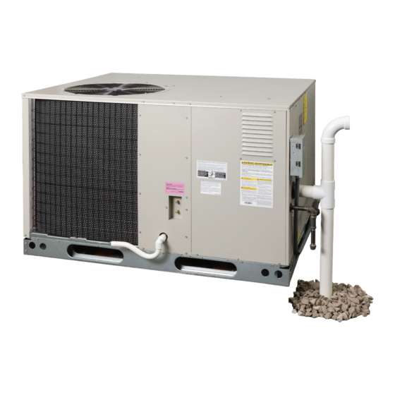
Page 36: Appendix - Heat Exchanger Condensate Drain & Vent System
Drain and Vent Kit (P/N 922323) that is available for is slightly acidic and some local codes may require purchase as an accessory item for R8HE series condensing a neutralizing treatment when disposing directly into style package gas/electric units. These instructions may be the ground. -
Page 37: Preparing The Pit
Vertical Drain Pipe Installation NOTE TO INSTALLER 1. After the pit has been dug out, pour the rock or chat READ THIS BEFORE YOU DIG! base to a level approximately 2” below the frost line. Mix in 50% of the limestone rock, chat, or lime pellets Before you begin digging the pit for the condensate (if required by code) with the initial rock base. -
Page 38: Preparing The Trench
2” elbow/reducer assembly resting on the REPLACEMENT PARTS rock base as shown in Figure 20. Replacement parts are available through all Nordyne 4. Cut the 3/4” vinyl drain hose and flexible insulation to distributors. Please have the complete model and serial the same length as the 2”... - Page 39 JOINTS A & B CAN BE MECHANICALLY FASTENED USING STANDARD 1/2” LONG SCREWS. THIS WILL MAKE DISASSEMBLY EASIER FOR FUTURE CLEANING OR INSPECTION OF THE VENT AND DRAIN SYSTEM. JOINT B DRAIN HOSE & INSULATION OUTER 2” PVC PIPE 2” PAD (FIELD SUPPIED) GRADE LEVEL GRADE LEVEL...
-
Page 40: Installation / Performance Check List
INSTALLATION / PERFORMANCE CHECK LIST GAS SYSTEM INSTALLATION ADDRESS: Natural Gas Type: (circle one) Propane CITY ________________________ STATE ________________ Gas pipe connections leak-tested? UNIT MODEL # ________________________________________ Gas Line Pressure: ____________________________ (in - W.C.) Is there adequate fresh air supply for UNIT SERIAL # _______________________________________ combustion and ventilation? Unit Installed Minimum clearances per...
Need help?
Do you have a question about the R8HE Series and is the answer not in the manual?
Questions and answers