Table of Contents
Advertisement
Quick Links
R6GP - 072/090/120 Series
Installation Instructions
Single Package Gas Heating/Electric Cooling Rooftop Units
FIRE OR EXPLOSION HAZARD
• Failure to follow safety warnings exactly
could result in serious injury or property
damage.
• Installation and service must be performed
by a qualifi ed installer, service agency or the
gas supplier.
• Do not store or use gasoline or other
fl ammable vapors and liquids in the vicinity
of this or any other appliance.
DO NOT DESTROY. PLEASE READ CAREFULLY AND KEEP IN A SAFE PLACE FOR FUTURE REFERENCE.
It is your responsibility to know this product better than your customer. This includes being able to install the product according to strict safety
guidelines and instructing the customer on how to operate and maintain the equipment for the life of the product. Safety should always be the
deciding factor when installing this product and using common sense plays an important role as well. Pay attention to all safety warnings and
any other special notes highlighted in the manual. Improper installation of the unit or failure to follow safety warnings could result in serious
injury, death, or property damage. These instructions are primarily intended to assist qualifi ed individuals experienced in the proper installation
of this appliance. Some local codes require licensed installation/service personnel for this type of equipment. After completing the installation,
return these instructions to the customer's package for future reference.
!
WARNING:
• Do not try to light any appliance.
• Do not touch any electrical switch; do not
use any phone in your building.
• Leave the building immediately.
• Immediately call your gas supplier from a
neighbors phone. Follow the gas suppliers
instructions.
• If you cannot reach your gas supplier, call
the fi re department.
ATTENTION INSTALLERS:
High Effi ciency
WHAT TO DO IF YOU SMELL GAS
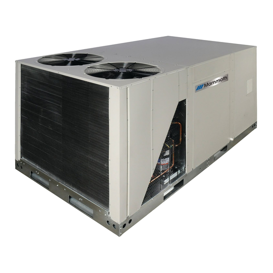
R6GP-090 Shown
Advertisement
Table of Contents

Subscribe to Our Youtube Channel
Related Manuals for Nordyne R6GP-072 Series

Summary of Contents for Nordyne R6GP-072 Series
- Page 1 R6GP - 072/090/120 Series High Effi ciency Installation Instructions Single Package Gas Heating/Electric Cooling Rooftop Units R6GP-090 Shown WARNING: FIRE OR EXPLOSION HAZARD WHAT TO DO IF YOU SMELL GAS • Failure to follow safety warnings exactly • Do not try to light any appliance. could result in serious injury or property •...
-
Page 2: Table Of Contents
Table 17- Gas Flow Rates ........43 Limit Control ............15 R6 Charging Charts ..........44 Verifying and Adjusting Firing Rate .......15 Figure 20 - R6GP-072 Series ......44 OPERATING SEQUENCE .........16 Figure 21 - R6GP-090 Series ......45 Cooling Mode ............16 Figure 22 - R6GP-120 Series ......45 Heating Mode (200 &... -
Page 3: Safety Information
SAFETY INFORMATION WARNING: Safety markings are used frequently throughout this manual to designate a degree or level of seriousness and The safety information listed below must be should not be ignored. WARNING indicates a potentially followed during the installation, service, and hazardous situation that if not avoided, could result in operation of this unit. -
Page 4: Requirements And Codes
• CANADA: Natural Gas and Propane Installation Codes numbers. This information can also be found online at (NSCNGPIC), Venting Systems and Air Supply for www.nordyne.com. Appliances Air Ducts Duct Systems • Air Ducts must be installed in accordance with the •... -
Page 5: Clearances To Combustible Materials
Clearances to Combustible Materials The condensate drain line must be J-trapped using fi eld supplied parts and may be combined with other drain • The R6GP series gas/electric unit is suitable for lines when routed to the drain. installation on combustible fl ooring or class A, B, or C roofi... -
Page 6: Venting Requirements
VENTING REQUIREMENTS • Ensure that the exhaust gases will not impinge on windows or building surfaces, which may be compromised or damaged by condensation. WARNING: • Do not install the unit in a location where exhaust from the vent termination will be directed into windows, This unit is intended for outdoor installation stairwells, under decks, or other recessed areas. -
Page 7: Unit Installation
UNIT INSTALLATION Rigging and Hoisting WARNING: Packaging Removal 1. Remove top crate brackets and wooden cap assembly To avoid the risk of property damage, personal from top of unit (Figure 3). 2. Remove lower crate brackets, 4 side skids, and 2 end injury, or death, it is the rigger’s responsibility skids from each side of unit. -
Page 8: Minimum Clearance Requirements
required under the unit. Supports must be made of Minimum Clearance Requirements steel or weather resistant wooden materials. The unit R6GP units are certifi ed as combination heating and must be square and level to ensure proper condensate cooling equipment for outdoor installation only. Figure 6 drainage. -
Page 9: Circulating Air Supply
CIRCULATING AIR SUPPLY be designed so that the return air supply to the unit is equal to the return air supply under normal, indoor return air applications. WARNING: Additional reference information for US and Canadian Do not allow combustion products to enter the installations can be found in the Duct Systems section return air ductwork or the circulating air supply. -
Page 10: Gas Supply And Piping
GAS SUPPLY AND PIPING This unit only has right side gas entry. When connecting the gas, provide clearance between the gas supply line All gas piping must be installed in compliance with local and the entry hole in the unit’s casing to avoid unwanted codes and utility regulations. -
Page 11: Conversion To Lp/Propane
WARNING: INSTALLATION EXAMPLE: Elevation: ..........3,890 feet The reduction of input rating necessary for high Type of Gas: ..........Natural altitude installation may only be accomplished Unit Model: ......R6GP-090C200C with factory supplied orifi ces. Do not attempt to drill out orifi ces in the fi eld. Improperly drilled orifices may cause fire, explosion, carbon At 4,000 feet, the unit needs to be derated by 4% for each 1,000 feet of elevation. -
Page 12: Line Voltage
Line Voltage Unbalanced 3-Phase Supply Voltage It is recommended that the line voltage to the unit be Voltage unbalance occurs when the voltages of all phases supplied from a dedicated branch circuit containing the of a 3-phase power supply are no longer equal. This correct fuse or circuit breaker for the unit. -
Page 13: Blower Speed
Blower Speed T-Stat Wire Recommended T-Stat Wire The blower speed is preset at the factory but must Gauge Length - Ft. (Unit to T-Stat) be verifi ed at each installation. For optimum system 18 Ga. 0 - 60 performance and comfort, it may be necessary to change the factory set speed. -
Page 14: Startup Procedures
√ Verify the power supply branch circuit overcurrent 5. Allow the unit to run for several minutes. Set the temperature selector above room temperature and protection is properly sized. √ Verify all exterior panels have been reinstalled and verify that the fan, blower, and compressors cycle off with the thermostat. -
Page 15: Verifying Burner Operation
Verifying Burner Operation Follow the steps below to determine the unit fi ring rate: • For installations at 2,000 feet and less, the fi ring rate WARNING: is the same as shown on the unit rating label. • For installations above 2,000 feet, compute the correct Uninsulated live components are exposed when fi... -
Page 16: Operating Sequence
OPERATING SEQUENCE Heating Mode for 100 & 166 kBtuh Heat Exchangers: The operating sequences for the heating, cooling, and 1. On a call for heat, the thermostat closes, applying 24 fan modes are described below. Refer to the wiring VAC to the W1 terminal (and W2 terminal if Stage 2 diagrams (Figures 15 - 19, pages 37 - 41). -
Page 17: Troubleshooting
UNIT MAINTENANCE TROUBLESHOOTING If the unit does not operate properly in the cooling NOTE: These maintenance instructions are primarily mode, check the following: intended to assist qualifi ed technicians experienced in the • The thermostat is operating properly. proper maintenance and operation of this appliance. •... -
Page 18: Blower Compartment
Blower Compartment 8. Remove four screws securing the burner assembly to the unit. Build up of dirt and lint on the blower and motor can create 9. Carefully remove the burner assembly from the unit. excessive loads on the motor resulting in higher than DO NOT DAMAGE THE IGNITOR WHILE REMOVING normal operating temperatures and possible shortened THE BURNER ASSEMBLY. -
Page 19: Vent Cover Assembly
the drill alternating between forward and reverse, Refrigerant Charging working the cable in and out several times to obtain The R6 Series packaged gas/electric units are fully charged suffi cient cleaning. Repeat this sequence for each at the factory and when installed accordingly, no charging heat exchanger tube. -
Page 20: Component Functions
COMPONENT FUNCTIONS High Pressure Switch This factory installed switch is designed to de-energize The descriptions below are various functional components the unit when excessive pressure occurs due to abnormal that affect the operation and shutting down of this unit. conditions. Under normal conditions, the switch is closed. Some of these components and their locations are shown If the discharge pressure rises above 650 psig, then the in Figure 11 (page 21). -
Page 21: Figures And Tables
FIGURES AND TABLES Model R6GP-120C235C Shown Evaporator Coils Quick Release Condenser Fan Filter Panel Durable Pre-Coat Assemblies Paint Easy Access Control Panel Electrical Control Wiring Entry Disconnect Mounting Condenser Coils Panel + Power Wiring Entry Exhaust Vent High/Low Pressure Switch Protection Permament Baserail - No Need for Removal... -
Page 22: Physical Dimensions
BOTTOM POWER KIT CONDENSATE MOUNTING LOCATION DRAIN 30 3/4 Shown with optional horizontal duct panels Horz. Return Air Opening* (762) 43 1/2 16 1/2 (1403) (419) 16 1/2 (102) (419) (762) 7 (178) REAR VIEW 7 1/4 (184) Figure 12. R6GP-072 Series... - Page 23 Return Air Opening 5-3/4 (146) 16 1/2 16 1/2 (419) (419) 30 1/2 (775) 30 1/2 (775) Discharge Air Opening 8 3/4 (222) Power † Entry 62 (1575) 101 1/4 (2572) BOTTOM PAN TOP VIEW Figure 12. R6GP-072 Series - Continued...
- Page 24 Corner “A” Corner “D” Heat Exchanger Condenser Access Fans Corner “B” Corner “C” TOP VIEW Blower Assembly 101 1/2 (406) (2578) (102) Optional Field Wiring Control Access Hail Guard (†)Electric Element Hood Access Blower Access FRONT VIEW Condesate Drain 4 (102) 2 (51) 30 3/4 (781)
- Page 25 INDUCER 57 1/2 RATING EXHAUST (1460) LABEL RECOMMENDED LOCATION COMBUSTION FOR UNIT DISCONNECT AIR LOUVERS GAS INLET (1092) 14.61 (371) UNIT BASERAIL 6.08 (154) HEAT EXCHANGER END Airflow Airflow Compressors (x2) CONDENSER END 7 (178) 7 (178) Return Air Opening 5-3/4 (146) 16 1/2 16 1/2...
- Page 26 Dimensions shown in inches (mm) Corner “A” Corner “D” Filters (x4) Evaporator Condenser Fans Corner “C” Corner “B” Blower TOP VIEW Assembly 101 1/2 (406) (2578) (102) Optional Control Access Hail Guard Hood Recommended Unit Disconnect Mounting Location Blower Access FRONT VIEW Condensate Drain...
- Page 27 57 1/2 (1461) Airflow Airflow 18 1/2 (470) Optional Fresh Air Condenser Coil Intake Hood Compressors (2) 9 7/8 (250) Optional Relief Hood 8 (203) Gas Inlet 4 (102) CONDENSER END HEAT EXCHANGER END 7 (178) 7 (178) Return Air Opening 5-3/4 (146) 16 1/2...
-
Page 28: Blower Performance Data
BLOWER PERFORMANCE DATA Table 5. R6GP-072C - 100 Series - Downfl ow Confi guration... - Page 29 Table 6. R6GP-072C - 100 Series - Horizontal Confi guration...
- Page 30 Table 7. R6GP-072C - 166 Series - Downfl ow Confi guration...
- Page 31 Table 8. R6GP-072C - 166 Series - Horizontal Confi guration...
- Page 32 Table 9. R6GP-090C Series / 230V - Downfl ow Confi guration...
- Page 33 Table 10. R6GP-090C Series / 230V - Horizontal Confi guration...
- Page 34 External Static Pressures (Inches Water Column) Motor Sheave Model Position 1 Turn Open 1.5 Turns Open 2.0 Turns Open 4522 2.03 (2 HP) 2.5 Turns Open 4552 1.92 4370 1.82 Static 3.0 Turns Open 4502 1.70 4387 1.70 4217 1.60 Drive 3.5 Turns Open 4438...
- Page 35 External Static Pressures (Inches Water Column) Motor Sheave Model Position CFM RPM Kw CFM RPM CFM RPM Kw CFM RPM Kw CFM RPM 1.5 Turns Open 2.0 Turns Open 4622 2.16 2.5 Turns Open 4686 2.09 4482 1.98 (2 HP) 3.0 Turns Open 4560 1.90 4342...
-
Page 36: Electrical Information
ELECTRICAL INFORMATION Outdoor Indoor Single Model Nominal Voltage Range Compressors (2) ea. motors Motor Circuit Number Electric (2) ea. (R6GP-) Supply Qty. 072C-100C 208-230/60/3 30.0 072D-100C 460/60/3 16.0 072C-166C 208-230/60/3 30.0 Factory 072D-166C 460/60/3 16.0 Drive 090C-200C 208-230/60/3 13.1 83.1 40.3 Data: 090D-200C... - Page 37 CCH1 Figure 15. Ladder Diagram - 072 -100/166 Series...
- Page 38 CCH2 CCH1 Figure 16. Ladder Diagram - 090/120 Series...
- Page 39 Figure 17. Wiring Diagram - 072 Series...
- Page 40 TRANSFORMER Figure 18. Wiring Diagram - 090 Series...
- Page 41 TRANSFORMER Figure 19. Wiring Diagram - 120 Series...
-
Page 42: Gas Information
GAS INFORMATION CAPACITY OF BLACK IRON GAS PIPE (CU. FT. PER HOUR) FOR NATURAL GAS (SPECIFIC GRAVITY - 0.60) LENGTH OF PIPE RUN (FT) NOMINAL BLACK IRON PIPE DIAMETER (IN.) 1 1/4 1050 1 1/2 1600 1100 NOTES The cubic feet per hour listed in the table above must be greater than the cubic feet per hour of gas fl ow required by the furnace. To determine the cubic feet per hour of gas fl... - Page 43 GAS FLOW RATE (CUBIC FEET PER HOUR) TIME FOR CUBIC FEET PER REVOLUTION TIME FOR CUBIC FEET PER REVOLUTION ONE REVOLUTION OF GAS METER ONE REVOLUTION OF GAS METER (SECONDS) (SECONDS) 1800 3600 1500 3000 1286 2571 1125 2250 1000 2000 1800 1636...
-
Page 44: R6 Charging Charts
R6 CHARGING CHARTS Application notes on the use of Charging Charts: This equipments cooling systems contain refrigerant under To inspect a systems operation, using quality instruments, high pressure, always use safe practices when servicing match the measured liquid temperature to the units chart. the unit. - Page 45 R6GP-090*-200C - Charging Chart - Cooling Operation Two stage refrigeration system - See Application Notes for use 5 8 0 5 5 5 5 3 0 5 0 5 R e m o ve re frig e ra n t w h e n a b o ve cu rve 4 8 0 4 5 5 4 3 0...
-
Page 46: R6 Gas Valve Labels
R6 GAS VALVE LABELS FOR YOUR SAFETY READ POUR VOTRE SÉCURITÉ. À LIRE AVANT L’EMPLOI BEFORE OPERATING ATTENTION! L’inobservation de ces instructions WARNING: If you do not follow these instructions peut entraîner un incendie ou une explosion pouvant exactly, a fi re or explosion may result causing property causer des dam mages à... - Page 47 POUR VOTRE SÉCURITÉ. FOR YOUR SAFETY READ BEFORE OPERATING À LIRE AVANT L’EMPLOI ATTENTION! L’inobservation de ces instructions WARNING: If you do not follow these instructions peut entraîner un incendie ou une explosion pouvant exactly, a fi re or explosion may result causing property causer des dam mages à...
-
Page 48: Installation Checklist
INSTALLATION/PERFORMANCE CHECK LIST INSTALLATION ADDRESS: INSTALLER NAME: CITY ________________________ STATE ________________ CITY _______________________ STATE ________________ UNIT MODEL # ________________________________________ GAS SYSTEM: Natural Propane UNIT SERIAL # ________________________________________ Gas Type: (circle one) Gas pipe connections leak-tested? Unit Installed Minimum clearances per Figure 6 (page 9)? Gas Line Pressure: _____________________________(in - W.C.) Is there adequate fresh air...
Need help?
Do you have a question about the R6GP-072 Series and is the answer not in the manual?
Questions and answers