
Related Manuals for flamco FlexFiller Direct G4


Summary of Contents for flamco FlexFiller Direct G4
- Page 1 FlexFiller Direct G4 Installation and operating manual www.flamcogroup.com/manuals...
-
Page 2: Table Of Contents
Installation requirements ..................12 Installation diagram .................... 13 Clearance requirements ..................14 Hydraulic connections ..................15 Controller ......................16 Connectivity options .................... 18 Electrical installation ..................... 19 Alarm installation ....................19 Operation ......................20 Shut-down procedure ..................21 Manual FlexFiller Direct G4... - Page 3 Restarting ......................21 Maintenance ......................22 10.1 Maintenance intervals ..................22 10.2 Visual inspection ....................23 10.3 Interrogate controller ..................23 10.4 Test unit operation ....................24 Decommissioning / Dismantling ................24 Appendix 1. Icon library ....................25 Appendix 2. Markings ....................28 Appendix 3.
-
Page 4: Warranty
If the unit is identified with a manufacturing defect within the warranty period, then no charge is made for correcting the defect. Flamco reserve the right to supply a replacement product in lieu of an engineer visit. Removal and reinstallation costs, along with consequential losses are not covered by this warranty agreement. -
Page 5: Conditions Of Warranty
We reserve the right to make technical changes subject to the future development of the Flamco product referred to in this publication. Hence no rights may be derived from technical data, descriptions and illustrations. Technical pictures, drawings and graphs do not necessarily correspond to the actual assemblies or parts as delivered. -
Page 6: About This Manual
<Inequality symbols> A message/fault code displayed on the digital controller Where to find more information? For the Quick Start Guide and further documentation in various languages, visit: www.flamcogroup.com/manuals For further information please visit the Flamco Limited Website at the following URL: www.flamco.co.uk Manual FlexFiller Direct G4... -
Page 7: Safety
Room which meets the applicable European and local regulations, standards and relevant technical rules and guidelines of the professional associations for this field of application. For the use of the FlexFiller Direct G4 as prescribed in this manual these rooms generally contain equipment for thermal generation and distribution, water heating/cooling and top-up, power source and distribution, such as measuring, control engineering, control technology and IT. -
Page 8: Staff Qualification
The product must be installed by a Qualified Person with regard to the following relevant requirements: • The Health and Safety Regulations • Building Regulations • IEE Regulations • Water Supply (Water Fittings) Regulations • Water By-laws (Scotland) • Any other by-laws or planning requirements. Manual FlexFiller Direct G4... - Page 9 All Flamco products should be installed by a Qualified Person with the relevant qualifications to carry out the required services and be physically and psychologically capable. The area of responsibility, competence and supervision of personnel is the duty of the Operator.
-
Page 10: Product Description
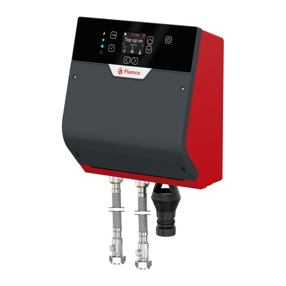
Product description The FlexFiller Direct G4 is the most compact, wall-mounted, pressurisation unit in the portfolio. The function of this pressurisation unit is to provide a means of automated water filling and top-up to sealed heating and cooling systems. The equipment is designed to provide periodic water top-up to compensate for minor losses in system pressure (e.g. -
Page 11: Technical Datasheet
Technical datasheet WRAS approval number KUKreg4: 2202704 WRAS: 2203331 General Size of the unit (Height x Width x Depth) 359mm x 225mm x 141mm Dry weight 4 kg Connection details Cold water inlet 15mm Compression System outlet 15mm Compression Drain (via Tundish) 22mm Compression &... -
Page 12: Installation Requirements
Installation requirements The FlexFiller Direct G4 is a wall mounted unit and should be installed at a suitable eye level, where the screen is easy to read and maintenance remains practical and possible. The wall of the set-up location for the FlexFiller Direct G4 must be such that stability is guaranteed and maintained. -
Page 13: Installation Diagram
Isolation Valves Valves 3-Way FlexBalance Valve Hydraulic Balancer Drain Isolation Point Valve FlexFiller Direct G4 Pressurisation Unit Isolation Valves Flexcon Expansion Vessel Mains To Drain Cold Supply We reserve the right to change designs and technical specifications of our products. -
Page 14: Clearance Requirements
Clearance requirements Clearance guidelines for service and repair. 120 mm 35 mm 35 mm 800 mm 120 mm Manual FlexFiller Direct G4... -
Page 15: Hydraulic Connections
Hydraulic connections From the “Manual-mode” in the controller menu, a testing routine can be triggered to check if the device is set up correctly and working accordingly. Each actuator (valve) can be operated separately with a maximum run-time of 2 minutes. The mains water and sealed system connection to the unit must be made using the flexible hoses with isolation valves provided. -
Page 16: Controller
Power indicator (orange=power) Status indicator (green=ok automat running) Bluetooth Not Availible Error/alarm (red=alarm/error active) Confirm button Return button Navigation buttons Screen on/of (hold 8 sec for powerdown) Not Availible USB-A software update + logging Not Availible Manual FlexFiller Direct G4... - Page 17 RS485 Modbus/Bacnet/HFC over RS485 1 B+ 2 B- 3 GND Fuse 1 (P31&P32) 5x20 5A Fuse 2 (P33&P35) 5x20 10AT Fuse 2 (P34&P36) 5x20 10AT Mains power connector 3 PE Mains grommet Not Availible SELV, System pressure 0-5V 1 +VDC 3 signal 3 GND SELV, Inlet pressure 0-5V...
-
Page 18: Connectivity Options
(to download a new control SW) RS-485 The primary designation is to connect the Flexfiller Direct G4 to internet (via Gateway and HFC protocol). Alternatively – BMS via Modbus Alternatively – BMS via bacnet... -
Page 19: Electrical Installation
All operations must be carried out by a qualified electrician The Flamco equipment must be connected to a mains isolator switch with a contact gap of at least 3 m. It is recommended the switch should be installed within 2m of the equipment. -
Page 20: Operation
22345A13I2A 18 PRESSURE TO HIGH Top up on Top up o Drain open Anti Legione The system pressure is too high. Top-up disabled until 117.2 L 117.2 L 117.2 L 4:58 issue resolved. 12-04-2022 14:30 Clear Manual FlexFiller Direct G4... -
Page 21: Shut-Down Procedure
Check the FlexFiller Direct G4 operation once power supply has been restored and, if necessary, set the actual date and time values (overview menu options). We reserve the right to change designs and technical specifications of our products. -
Page 22: Maintenance
Such acts may result in serious personal injury and endanger operational safety. They will also render any claim for damages against product liability void. It is recommended to contact Flamco Customer Service (See Appendix 4: Contact)for carrying out these services. -
Page 23: Visual Inspection
The maintenance date will then automatically switch to the next required maintenance date. 5 Years after first commissioning, the Flexfiller Direct G4 will need an annual service to reset the reminders for the annual service. It is the homeowners responsibility to book the annual service to reset the controller. -
Page 24: Test Unit Operation
Water areas should first be made pressure-less and drained according with the applicable local rules. This water may be chemically treated, contain antifreeze or other additives. Further processing of the construction parts should be carried out in agreement with the required waste management service provider. Manual FlexFiller Direct G4... -
Page 25: Appendix 1. Icon Library
Appendix 1. Icon library Icon Description Location Home Accept/Confirm Arrow left & right System OK System at fault Menu Language ▶ ▶ Date & time ▶ ▶ Date ▶ ▶ ▶ Time ▶ ▶ ▶ Manual Summary System pressure ▶ Set pressure/ Cold fill pressure ▶... - Page 26 Settings General settings ▶ System info ▶ Service info Maintenance ▶ Next maintenance Fault log ▶ Active hours ▶ Log in/ Log out Account VFC relay ▶ ▶ Advanced settings (RS485, anti legionella, etc) ▶ ▶ Manual FlexFiller Direct G4...
- Page 27 Manual mode ▶ Login required to activate manual mode (Chapter 10) Factory settings reset ▶ ▶ Login required to activate manual mode (Chapter 10) Firmware update ▶ ▶ Login required to activate manual mode (Chapter 10) We reserve the right to change designs and technical specifications of our products.
-
Page 28: Appendix 2. Markings
Opening by qualified personnel only. Disconnect the unit from the power supply before opening it. Ac h t u n g , gefährliche Spannung! Nur vom Fachpersonal zu öffnen. Vor dem Öffnen des Gerätes spannungsfrei schalten. Manual FlexFiller Direct G4... -
Page 29: Appendix 3. Troubleshouting Guide
The unit is undersized for the Review unit selection system. Flood limit time is too short. Consult Flamco Supply pressure The isolation valve at the Open the isolation valves at the too low bottom of the unit is closed. - Page 30 System fill function again. Anti-legionella The unit is cleaning the pipes No action needed, this flush running by flushing water to the drain. procedure lasts approximately 2 minutes. Thereafter the unit will continue normal operation. Manual FlexFiller Direct G4...
- Page 31 The pressure sensor has failed. Replace pressure sensor System pressure The pressure output range is Consult Flamco sensor short circuit out of detectable area. Sensor needs calibrating. The pressure sensor has failed. Replace pressure sensor High pressure...
- Page 32 Unit will not top up until triggered above safety valve pressure. pressure has dropped below cold fill pressure. Vessel pre-charge The expansion vessel has failed Check the expansion vessel pressure changed or lost its pre-charge. pre- charge and re-charge if necessary. Manual FlexFiller Direct G4...
- Page 33 We reserve the right to change designs and technical specifications of our products.
- Page 34 Manual FlexFiller Direct G4...
- Page 35 We reserve the right to change designs and technical specifications of our products.
- Page 36 Copyright Flamco B.V., St Helens, United Kingdom. No part of this publication may be reproduced or published in any way without explicit permission and mention of the source. The data listed are solely applicable to Flamco products. Flamco Limited shall accept no liability whatsoever for incorrect use, application...
Need help?
Do you have a question about the FlexFiller Direct G4 and is the answer not in the manual?
Questions and answers