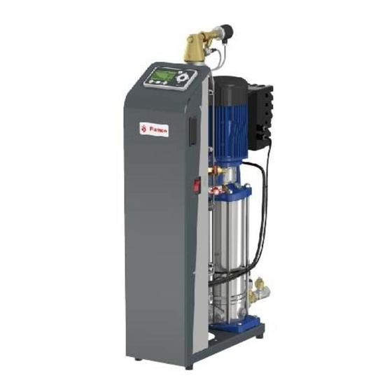
flamco Vacumat Eco 300 Installation And Operating Instructions Manual
Fully automatic stationary degassing and top-up machines
Hide thumbs
Also See for Vacumat Eco 300:
- Installation and operating instructions manual (388 pages)

Related Manuals for flamco Vacumat Eco 300


Summary of Contents for flamco Vacumat Eco 300
- Page 1 ® Vacumat Eco www.flamcogroup.com/manuals...
- Page 2 H-2058 Budaörs, Pf. 73 Flamco B.V. +31 33 299 75 00 support@fl amco.nl Postbus 502 3750 GM Bunschoten Flamco Sp. z o. o. +48 616 5659 55 info@fl amco.pl ul. Akacjowa 4 62-002 Suchy Las Flamco Sverige +46 500 42 89 95 vvs@fl...
- Page 3 Vacumat Eco Installation and operating instructions Translation of the original operating instructions ____________________________________________________________________________________________ Montage- und Betriebsanleitung Orginalbetriebsanleitung ___________________________________________________________________________________________________________________________ Montage en gebruikshandleiding Vertaling van de oorspronkelijke gebruiksaanwijzing _______________________________________________________________________________________ Installation et mode d’emploi Traduction de la notice d’utilisation originale _________________________________________________________________________________________________ Instrucciones de instalación y funcionamiento Traducción de las instrucciones de funcionamiento originales __________________________________________________________________________ Istruzioni d’installazione e d’impiego...
-
Page 5: Table Of Contents
English (ENG) Instruction and installation manual Liability ............................................6 Warranty .............................................6 Copyright ...........................................6 General safety instructions ......................................6 Purpose and use of this manual ..................................6 ualifications re uired, assumptions ................................6 Staff ualification .......................................7 Intended use ........................................7 Incoming goods .........................................7 Transportation, storage, unpacking ...................................7 Operations room ........................................7 Noise reduction .........................................8 EMERGENCY-STOP / EMERGENCY-OFF ................................8... -
Page 6: Liability
This information is the result of our current findings and experience to the best of our knowledge. We reserve the right to make technical changes subject to the future development of the Flamco product referred to in this publication. -
Page 7: Staff Ualification
The e uipment is delivered in packing units in compliance with the contractual specifications, or re uirements for specific transport methods and climate zones. They meet the re uirements of the Flamco STAG GmbH packaging guidelines as a minimum. In accordance with these guidelines, the degassing systems are supplied stored on special pallets. These pallets are suitable for transportation with suitable fork-lift trucks. -
Page 8: Noise Reduction
The set-up location of the degassing e uipment must guarantee that the operation, servicing, testing, maintenance, assembly and disassembly can be performed regularly, without obstruction and safely. The surface forming the installation area for the e uipment must ensure stability and support. Bear in mind that the maximum possible forces comprise the deadweight including the water fill. If stability cannot be guaranteed, there is a danger that the unit will tip over, or move under load and, as a conse uence, cause injury to persons and malfunctions. -
Page 9: External Forces
The maximum pressure of system water in conducting components may be e ual to the maximum set pressure for the system s applicable safety valve. The Vacumat Eco 300 up to size 900 has a maximum positive working pressure of 10 bar. Use of eye / face protectors is re uired if the eyes or face could be injured by flying parts or spraying fluids. -
Page 10: Residual Hazards
4.20 Residual hazards Fire professional fire protection must be ensured on site. 4.21 Warning symbols in this manual Warning against hazardous electric current. Disregarding this could put lives at risk, cause fires or trigger accidents, lead to component overload and damage, or prevent functionality. -
Page 11: Components E Uipment
ompon n s / u pm n Control unit ON/OFF switch Service label with service contacts Plant type plate Ground connection for applying the external e uipotential bonding protective earth conductor Operator terminal Control unit SPC m1 2x mounting hole to ensure stability against tipping Rubber buffers for sound insulation insulation against structure-borne sound propagation... -
Page 12: Mode Of Operation
Mode of operation The Vacumat Eco works as an active degassing device with automatic top-up 5.4.1 Basic principle of degassing in the Vacumat Eco Degassing is performed by removing system medium from the system circulation through a bypass. This is conveyed through the system connection (A) and the following volume flow limiter 7 into the degassing vessel 8 . - Page 13 5.4.6 Operating mode - fully automatic Once the system has been fully set up Start menu completed and commissioned, and the control unit has been switched on, a delay first occurs then the temperature in the machine is initially adjusted for a preset period before it is measured. Based on the temperature and the preset check degassing mode, the process in the vessel is regulated so that, after a certain time, it is possible to determine at the pressure switch whether undissolved air still exists in the medium at the level predefined by the degassing mode.
-
Page 14: Marking
Type: Protection: N° de Série: Type: Volgnummer: Bescherming: Flamco STAG GmbH; Berliner Chaussee 29; 39307 Genthin; Germany Nennspannung: Zulässige Medientemperatur min. / max.: Nominal voltage: Permissible media temperature min. / max.: 1x 230 V 50/60 Hz 3 / 90 °C Tension nominale: Température de média mini. - Page 15 5.5.5 Label from the terminal board cover (inside) ATTENTION: ACHTUNG: Read the manual ! Even if unit is isolated from Trotz Netztrennung kann, an den Klemmen: 12, 13, 14, 16 power supply, terminals 12, Bedienanweisung lesen ! 13, 14, 16 and 17 may carry und 17 eine Spannung von SPC m1/V1.0 230V voltage!
-
Page 16: Assembly
6. Assembly Installing, levelling, bolting - Ensure stability! Set up the unit on a flat and stable concrete surface near the well in the operating boiler room. nsur a a floor ra n s a a la l un . se both frame holes on the base plate 12 to secure the Vacumat Eco against tipping. -
Page 17: Settings / Control Actions
19 different languages. Menu item 5: Log in supports the entry of access codes in order for service staff to carry out settings, including setting internal Flamco parameters. Menu item 6: Logout supports logging out after using access codes. - Page 18 Menu item 9: Start-up menu Only available as long as it has not yet been fully processed, for example, after initial commissioning or resetting the Start menu in the Configuration . → Read and acknowledge. Read the instruction manual 9-1:. →...
-
Page 19: Maintenance
8. Maintenance The components of the Vacumat Eco are largely maintenance-free. Nevertheless, it is recommended to perform an annual visual check of the system including for leaks . In addition, the dirt trap to be provided by the customer in the inflow line must be cleaned at least once a year, even if automatic detection does not re uire this. Cleaning may also be done at more fre uent intervals depending on how dirty the system water is . - Page 20 Error Error Error / Name Effect / Action holding/ message subject to mandatory acknowledgement Top-up Top-up without re uest IW Top-up off / check motor ball valve for leaks inadmissible delivers signals without supply for top-up. Top-up interval minimum top-up cycle interval Top-up of / correct defaults if necessary;...
-
Page 21: Pp N . C N Cal A A G N Ral Sp C Ca Ons
Appendix 1. c n cal a a g n ral sp c ca ons Ambient conditions Storage space/Operating area Room: Protected against: Ambient conditions: Locked; Solar radiation; 60 ... 70 relative humidity, non-condensing frost-free; thermal radiation; maximum temperature 50 °C; dry. -
Page 22: Example Of A Unit / Pipeline Integration
Example of a unit / pipeline integration ≥100 cm <10m min. DN20 >10m min. DN32 Max lengte = 20m (1x 90° Max L = 19m) (3x 90° Max L = 17m) <10m min. DN32 >10m min. DN40 Minimum distances: clearance for service and repair. 5 0 0 8 0 0 8 0 0... -
Page 23: Pp N . C N Cal A A Sp C Ca Ons
Appendix 2. c n cal a a sp c ca ons Vacumat Eco Fully automatic stationary degassing and top-up machines for heating and cooling water systems. Hydraulic connection data: Medium Water-based heat carrier as per VDI 2035 Max. glycol max working pressure range -10 , and no distilled water Nominal pressure PN 10 Working pressure range... -
Page 24: Appendix 3. Menu Structure Of The Spc M1 - Diagram
Appendix 3. Menu structure of the SPC m1 - diagram... -
Page 25: Appendix 4. Terminal Diagram
Appendix 4. Terminal diagram brown +24V black brown +24V / signal + blue blue analogue IN brown +24V / signal + blue analogue IN white AGND analogue IN fault FC GNDA brown INPUT Standby white OUT+ OUT- System blue brown green-yellow green-yellow blue... -
Page 26: Appendix 5. Optional Accessories And Their Integration
Appendix 5. Optional accessories and their integration Optional accessories and their integration Otherwise, the unit is fully set up. System separation by top-up unit (NFE) Top-up medium must be free of particles greater than 0.5 mm and long-fibered components. If the system still needs to be separated from the potable water network , it is possible to use NFE 1.1 and NFE1.2. See System layout - system diagram. -
Page 27: Appendix 6. Declaration Of Conformity
Appendix 6. Declaration of Conformity... - Page 28 The data listed are solely applicable to Flamco products. Für eine unsachgemäße Nutzung, Anwendung oder Interpretation der tech- Flamco B.V. shall accept no liability whatsoever for incorrect use, application or nischen Daten übernimmt Flamco B.V. keine Haftung. Technische Änderungen interpretation of the technical information.
Need help?
Do you have a question about the Vacumat Eco 300 and is the answer not in the manual?
Questions and answers