Table of Contents
Advertisement
Quick Links
Advertisement
Table of Contents

Related Manuals for Vents FlexiVent 0811125/63x2


Summary of Contents for Vents FlexiVent 0811125/63x2
- Page 1 INSTALLATION INSTRUCTION Modular air distribution system...
-
Page 2: Table Of Contents
СОДЕРЖАНИЕ Типовое решение ........................................3 CONTENTS Рекомендации по монтажу приточных и вытяжных диффузоров ..................4 Typical configuration .......................................3 Рекомендации по монтажу приточных решеток и анемостатов ..................4 Mounting recommendations for supply and exhaust diffusers ....................4 Рекомендации по монтажу вытяжных решеток и анемостатов ..................4 Рекомендации... -
Page 3: Типовое Решение
TYPICAL CONFIGURATION Ceiling-mounted plastic Round duct Connector pipe Plastic air distribution box Air handling unit with connector heat recovery Extract air disc valve Floor-mounted grille Flexible insulated air duct Outer ventilation hood Floor-mounted connector ventilation-system.com... -
Page 4: Рекомендации По Монтажу Приточных И Вытяжных Диффузоров
MOUNTING RECOMMENDATIONS FOR SUPPLY AND EXHAUST DIFFUSERS • When selecting supply and exhaust grilles and disk valves it is necessary to take into account the following factors: • Noise level. • Air flow. • Expansion of the air jet. Mounting recommendations for supply grilles and disk valves •... - Page 5 Exhaust grille location Supply air disk valve location 50 cm 50 cm 20 cm 20 cm Recommendations on positioning of supply and exhaust grilles Air extraction Air supply ventilation-system.com...
-
Page 6: Рекомендации По Расчету Толщины Перекрытия
Recommendations on calculation of slab thickness ≥ 3xDN Minimum thickness of a steel-reinforced concrete slab with air ducts containing combustible components according to DIN 4120 Fire resistance class High-rise buildings One family house Low-rise buildings Design features from 5 storeys F 30-A F 90-A Min. -
Page 7: Коллектор Металлический
PLASTIC AIR DISTRIBUTION BOXES FOR OVAL DUCTS The air distribution box is designed for wall, floor, and ceiling mounting. Fix the air distribution box to the mounting surface. Fasteners to be purchased separately. While choosing fasteners consider the material of the mounting surface and the unit weight. - Page 8 Insert the ducts into the flanges. Cover the unused flanges with plugs (not included in the delivery set). WARNING! If the ducts are to be covered with concrete, make sure to provide extra sealing for the joint between the duct and the flange and the joint between the flange and the plug using a cold shrink tape. Secure the air ducts and plugs on both sides with Connect the main air duct to the corresponding universal locks.
-
Page 9: Plastic Air Distribution Boxes For Round Ducts
PLASTIC AIR DISTRIBUTION BOXES FOR ROUND DUCTS The air distribution box is designed for wall, floor, and ceiling mounting. Fix the air distribution box to the mounting surface. Fasteners to be purchased separately. While choosing fasteners consider the material of the mounting surface and the unit weight. -
Page 10: Пленум Потолочный Металлический
Insert the ducts into the flanges. Cover the unused flanges with plugs (not included in the delivery set). WARNING! If the ducts are to be covered with concrete, make sure to provide extra sealing for the joint between the duct and the flange and the joint between the flange and the plug using a cold shrink tape. Secure each duct and each plug on both sides with Connect the main air duct to the corresponding universal locks. -
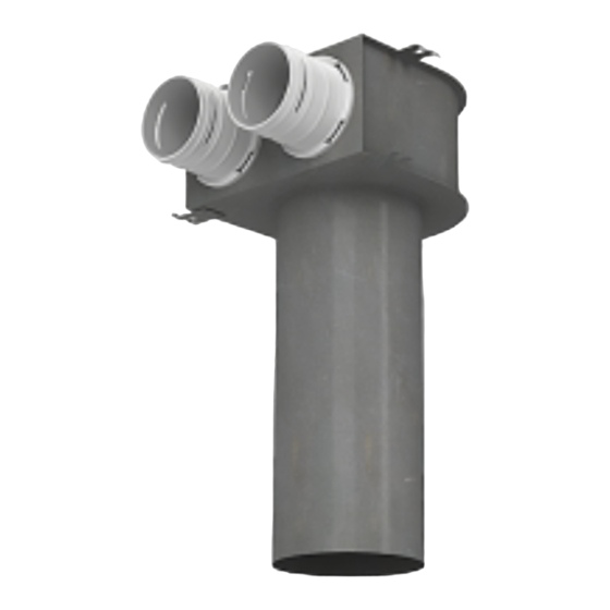
Page 11: Metal Air Distribution Boxes
METAL AIR DISTRIBUTION BOXES PREPARATION FOR MOUNTING If the air distribution box design enables changing location of the spigot, proceed as follows: 1. Unscrew the service panel and the spigot and disconnect 2. Change location of the spigot and the service these from the air distribution box. - Page 12 INSTALLATION OF A METAL AIR DISTRIBUTION BOX ON THE MOUNTING SURFACE The air distribution box is designed for wall, floor, and ceiling mounting. Fix the air distribution box to the mounting surface using bolts or threaded rods (not included in the delivery set). While choosing fasteners consider the material of the mounting surface and the unit weight.
- Page 13 MOUNTING OF FLANGES 0263, 0275 Before installation, make sure that the flanges are sealed. Insert the flange into the slotted hole so that the open lock symbol on the flange is opposite the arrow on the casing. To secure in the hole, simultaneously press the lock in the flange towards the inner wall face and rotate the flange clockwise so that the closed lock on the flange faces the arrow on the casing.
- Page 14 CONNECTION OF SEMI-RIGID DUCTS Place two seals on each duct end on the flange connection side. WARNING! If the ducts are to be covered with concrete, make sure to provide extra sealing for the joint between the duct and the flange and the joint between the flange and the plug using a cold shrink tape. Fixing the air ducts with a lock ring 1.
-
Page 15: Пленум Потолочный Пластиковый
PLASTIC CEILING CONNECTORS FOR ROUND DUCTS Mounting of the connector in the floor slab Drill a 130 mm hole in the non-removable slab Install and fix the connector. formwork for a 125 mm spigot of the connector. Fill the gaps between the spigot and the formwork surface with sealant (mounting foam). - Page 16 Lay the ducts, securing them to the formwork with Place two seals on each duct end on the flange masking tape if necessary. connection side. WARNING! Before the ducts are covered with concrete, make sure to provide extra sealing for the joint between the duct and the flange and the joint between the flange and the plug using a cold shrink tape.
-
Page 17: Пленум Напольный Металлический
Ceiling mounting of the connector Use the connector casing to mark and drill holes for Fasten the connector to the ceiling. fixing. While choosing fasteners (to be purchased separately) consider the material of the mounting surface as well as the weigh of the unit. - Page 18 Insert the air ducts with the sealing rings into the Secure the ducts in the flanges on both sides using flanges. the universal locks. Close the unused flanges with plugs. Secure the plugs in the flanges on both sides using the universal locks (included in the flange delivery set).
- Page 19 Mount the false ceiling and prepare a hole in it for the Cut the protruding part of the spigot flush with the connector outlet. ceiling, protecting the surface from damage with cutting tools. After finishing work, install the air disc valves (not included in the delivery set).
-
Page 20: Plastic Ceiling Connectors For Oval Ducts
PLASTIC CEILING CONNECTORS FOR OVAL DUCTS Mounting of the connector in the floor slab Drill a Ø 130 mm hole in the floor slab for a Ø 125 mm Install and fix the connector. connector spigot outlet. Fill the gaps between the spigot and the slab with sealant (mounting foam). -
Page 21: Пленум Настенный Металлический
Lay the air ducts by securing them to the surface with Put two seals on each end of the air ducts from the mounting tape. flange connection side. Put two seals on the plug. Insert the air ducts with the sealing rings into the Close the unused flanges with plugs. -
Page 22: Ceiling Mounting Of The Connector
Ceiling mounting of the connector Use the connector casing to mark and drill holes for Fasten the connector to the ceiling. fixing. While choosing fasteners (to be purchased separately) consider the material of the mounting surface as well as the weigh of the unit. -
Page 23: Переходная Flexivent-Пластивент
Insert the ducts with the seals into the flanges and Close the unused flanges with plugs and fix them on secure them on both sides using the universal locks (included both sides with universal locks (included in the flange delivery in the delivery set). -
Page 24: Ceiling-Mounted Metal Connectors
CEILING-MOUNTED METAL CONNECTORS Ceiling mounting of the connector Use the connector casing to mark and drill holes for Fasten the connector to the ceiling. fixing. While choosing fasteners (to be purchased separately) consider the material of the mounting surface as well as the weigh of the unit. -
Page 25: Воздуховод Flexivent
Remove the lock rings from the flanges (supplied Insert the ducts into the flanges. with the flanges). Close the unused flanges with plugs. Secure the duct and the plugs using the lock rings. Prepare a Ø130 mm hole in the ceiling for installation Protect the mounting surface against damages with of the connector spigot and install the suspended ceiling. -
Page 26: Plastic Floor-Mounted Connector For Oval Ducts
PLASTIC FLOOR-MOUNTED CONNECTOR FOR OVAL DUCTS Mounting the connector on top of the slab into the thickness of the floor insulation Make markings on the slab for mounting holes. Use the connector as a template. Drill three holes according to the marking and fix the connector to the surface. ventilation-system.com... -
Page 27: Воздуховод Гибкий Изолированный Изовент
Lay the air ducts by securing them to the surface with Put two seals on each end of the air ducts from the mounting tape. flange connection side. Put two seals on the plug. Insert the ducts with the seals into the flanges and Close the unused flanges with plugs and fix them on secure them on both sides using the universal locks (included both sides with universal locks (included in the flange delivery... -
Page 28: Соединение И Стыковка Гибких Изолированных Воздуховодов
FLOOR-MOUNTED METAL CONNECTORS Mounting of the connector into the slab with concrete casting Make markings on the non-removable formwork of the slab for fixing holes. Use the connector as a template. Drill holes according to the marking and fix the Remove the lock rings from the flanges (supplied with connector to the surface. -
Page 29: Крепление Гибких Изолированных Воздуховодов
Lay the air ducts by securing them to the surface with Place two seals on each duct end on the flange mounting tape. connection side. WARNING! Before the ducts are covered with concrete, make sure to provide extra sealing for the joint between the duct and the flange and the joint between the flange and the plug using a cold shrink tape. -
Page 30: Введение Вентиляционной Системы В Эксплуатацию
VENTILATION GRILLE MOUNTING Installation of a ventilation grille Cut the protruding part of the connector to be flush with the floor. The floor surface must be protected against damages with cutting tools. 1. Insert the grille into the connector after installation of the 2. - Page 31 Installation of a flush-mounted ventilation grille Cut the protruding part of the connector to be flush with the finishing screed before laying the finish floor. The floor surface must be protected against damages with cutting tools. 1. Insert the frame into the connector prior to installation of 2.
-
Page 32: Регулирование Расхода Воздуха
WALL-MOUNTED METAL CONNECTOR Bore a rectangular core hole in the wall. Insert the connector in the opening. Seal the gaps between the connector and the wall with expanding foam. ventilation-system.com... - Page 33 Remove the lock rings from the flanges (supplied with Cover the unused flanges with caps (not included in the flanges). the delivery set. Lay the air ducts by securing them to the surface with Place two seals on each duct end on the flange mounting tape.
-
Page 34: Flexivent-Plastivent Adapter Sleeve
FLEXIVENT-PLASTIVENT ADAPTER SLEEVE Connect the elements of the Plastivent system and Lay the air ducts by securing them to the surface with secure them to the surface with the Plastivent fastener. mounting tape. Secure the Flexivent-Plastivent adapter sleeve to the ceiling with perforated mounting tape. - Page 35 Insert the air ducts with the sealing rings into the Cover the unused flanges with plugs (not included in flanges. the delivery set). Secure the ducts and the plugs using the lock rings. Mount the ventilation grille upon completion of the interior decoration works.
-
Page 36: Flexivent Air Duct
FLEXIVENT AIR DUCT Cut the air duct to the required length. To prevent construction debris from entering the air ducts during installation, close them with plugs. Cover the air duct with the sealing ring for airtight connection with the flange. Two sealing rings should be used to provide air tightness of the class D. - Page 37 The air ducts are fixed in the fittings with a latch or universal locks on both sides. The bends are fixed to the mounting surface with screws. Vertical oval bend Horizontal oval bend Horizontal round bend WARNING! If the ducts and the air distribution box are to be covered with concrete, make sure to provide extra sealing for the joint between the duct and the flange using a cold shrink tape.
-
Page 38: Flexible Insulated Air Duct Isovent
FLEXIBLE INSULATED AIR DUCT ISOVENT General recommendations When installing flexible insulated ducts, it is necessary to take into account the route of laying, the number of bends, the angle of bends and the number of deflections between the fixing points, since these factors affect the resistance of the ducts. Use a minimum flexible air duct length for connection of ventilation elements. -
Page 39: Joining Of Flexible Insulated Air Ducts
Joining of flexible insulated air ducts The flexible insulated air duct must cover the flange of the fitting to which it is secured for not less than 50 mm. The nipple used for attaching air ducts should be not less than 100 mm. A corresponding adhesive tape and clamp should be used for providing air tightness and fixation of a joint. -
Page 40: Commissioning Of The Ventilation System
Ensuring the necessary minimum of air exchange in separate rooms. • General check • Only ventilation components made by Vents were used for installation. • Mounting is completed and the facility is ready to be put into operation. • Supply grilles and/or disk valves are in place. - Page 41 Connection of a differential pressure switch to air ducts for pressure difference measurement Supply Extract Intake Exhaust Anemometer Anemometer Air flow regulation through ventilation grilles or disk valves in the rooms An anemometer with an appropriate funnel should be used for measuring of the air flow through a ventilation grille. Measurement of the air flow through a ventilation grille or disk valve Funnel Anemometer...
-
Page 42: Air Flow Control
AIR FLOW CONTROL Air flow rate control with a disc valve The air flow rate through the air disc valve is adjusted by rotating its central part. Air flow regulation by means of installing the air throttling damper into the air distribution box 1. -
Page 43: Air Flow Regulation By Means Of Installing The Air Throttling Damper Into The Connector
Air flow regulation by means of installing the air throttling damper into the connector 1. Cut the jumpers between the air throttling damper rings with a knife and remove the excess rings. 2. Remove the ventilation grille from the connector. 3. - Page 44 All rings are in places FlexiVent 0763 rings removed - 1 rings removed - 2 rings removed - 3 All rings are cut out Air flow [m All rings are in places FlexiVent 0775 rings removed - 1 rings removed - 2 rings removed - 3 rings removed - 4 All rings are cut out...
-
Page 45: Air Flow Control In The Connector With A Rectangular Air Throttling Damper
Air flow control in the connector with a rectangular air throttling damper 1. Remove the ventilation grille. 2. Remove the excess inserts in the air throttling damper by using a knife to cut the jumpers holding them in place. 3. Place the air throttling damper in the connector. 4. -
Page 46: Air Flow Control In The Connector With A Circular Air Throttling Damper
Air flow control in the connector with a circular air throttling damper 1. Remove the grille from the connector. 2. Remove the excess inserts in the air throttling damper by using a knife to cut the jumpers holding them in place. 3. -
Page 47: Technical Maintenance
TECHNICAL MAINTENANCE Maintenance includes general cleaning of system components to remove dirt and dust deposits. 1. Cleaning of the air ducts. Clean the air ducts using a specially designed brush or a vacuum cleaner nozzle that matches the flange. The access to the air ducts is provided through the service panel and the ventilation grille. 2. - Page 48 V156EN-02...
Need help?
Do you have a question about the FlexiVent 0811125/63x2 and is the answer not in the manual?
Questions and answers