
Subscribe to Our Youtube Channel
Related Manuals for Lionel LCS BPC2


Summary of Contents for Lionel LCS BPC2
- Page 1 78-1640-250 8/14 BLOCK BLOCK BPC2 6-81640 LCS PDI CABLES PROGRAM AC Power use either connector Lionel Block Power Controller 2 (BPC2) Owner's Manual...
-
Page 2: Table Of Contents
But until now, combining those parts into a complete system could be a challenge. Lionel’s new Layout Control System or “LCS,” fulfills the LEGACY promise of integrated locomotive and layout control. - Page 3 The following Lionel marks are used throughout this Owner’s Manual and are protected under law. All rights reserved. Lionel ® , LionChief ™ , LionChief Plus ™ , LEGACY ™ , FasTrack ® , TrainMaster ® , Odyssey ® , RailSounds ®...
-
Page 4: What Is Lionel's Layout Control System
What is Lionel’s Layout Control System? LCS doesn’t replace your existing Lionel Legacy Control system. It adds to it! You can control your layout from Lionel Cab Remote controllers or from smart devices like an Apple iPad and run locomotives, operate track switches, accessories and lighting. Create automatic events to control passing locomotives and other layout accessories or switches. -
Page 5: Lcs Bpc2 Module
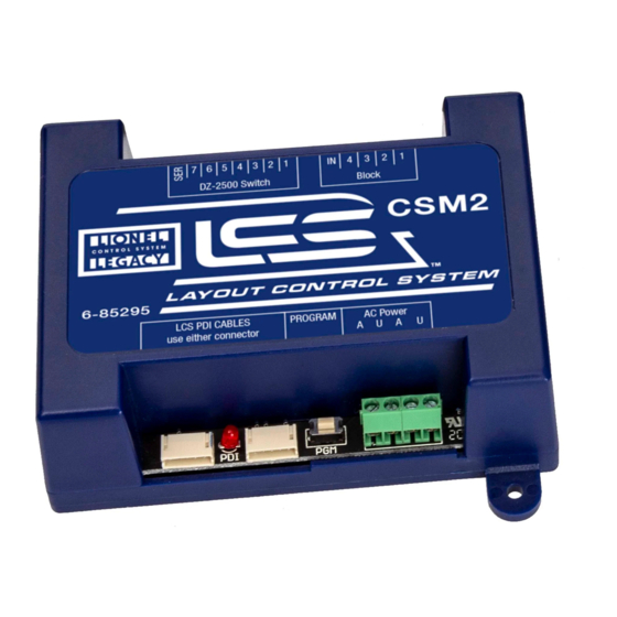
PROGRAM AC Power use either connector Figure 2. LCS BPC2 Module Wiring your railroad for blocks has several advantages: • By turning off track power blocks when not in use, you can store additional trains and reduce the draw on your power supplies in either conventional or command control. -
Page 6: Installing Your First Lcs Device
LCS component, please skip ahead to the next section titled “Installing additional LCS devices.” When installing a new LCS system, the process you will follow depends on which (if any) Lionel Command Base is to be connected to your LCS system. The following sections describe starting a new LCS installation with a Legacy Base, a Base-1L, or without any command base. -
Page 7: Installing A New Lcs System With A Legacy Base
Figure 4. Installing a new LCS system with a LEGACY Base Once connected and powered-up, the yellow LED on the Legacy Base will blink once every second. With this setup, you can control Lionel locomotives and Layout Control System products using a Legacy Remote(s) and optionally CAB-1L remote(s). -
Page 8: Installing A New Lcs System With A Base-1L
Figure 5. Installing a new LCS system with a Base-1L Once connected and powered-up, the red LED on the Base-1L will blink once every second. With this setup, you can control Lionel locomotives and Layout Control System products using a CAB-1L remote(s). -
Page 9: Installing Lcs With Legacy And Trainmaster Command Bases
Installing Your First LCS Device Installing LCS with Legacy AND TrainMaster Command Bases he following instructions apply ONLY if you are using one or more original CAB-1 remotes with a Legacy command base. It is not necessary to follow these instructions to use the CAB-1L remote with a Legacy command base. - Page 10 Once connected and powered-up, the yellow LED on the Legacy Base will blink once every second. With this setup, you can control Lionel locomotives and Layout Control System products using any combination of LEGACY Remotes, CAB-1L remotes and original CAB-1 remotes.
-
Page 11: Installing A New Lcs System With No Command Base
DCC. An LCS WiFi is required, as are one other LCS module (such as ASC2 or BPC2). To install a new LCS system on a layout that does NOT include Lionel Command Base: 1. Connect the DC wall-pack to the female cable-mount connector of the LCS DB-9 Cable. -
Page 12: Installing Additional Lcs Devices
The order of devices in the “chain” is up to you. The only exception is that an LCS WiFi must be the first device in the chain if no Lionel Command Base is present. To connect each additional LCS device: 1. -
Page 13: Configuring Your Bpc2
LCS BPC2 module. The function of each is described on following pages. A – Track Power Block terminals should be connected to electrically-isolated track power blocks. -
Page 14: Connect Accessory Transformer To Relay Power Terminals
Configuring Your BPC2 Connect Accessory Transformer to Relay Power Terminals our BPC2 requires an external power source to operate its 8 internal relays. This must be supplied from a separate accessory transformer. Connect an accessory transformer with an 12-14 VAC output to the BPC2’s front screw terminal connections marked “A” and “U” as shown in Figure 9 below. -
Page 15: Understanding Bpc2 Software Configuration
Configuring Your BPC2 Understanding BPC2 Software Configuration Your BPC2 software configuration is a single operation that controls four distinct areas: 1. Track Addressing vs. Accessory Addressing 2. The base address/TMCC ID used to control connected track power blocks 3. The optional "restore last relay settings on power-up" mode. When selected, any track blocks that were powered on when you last shutdown your layout will be automatically turned on at power-up. -
Page 16: Configuring The Bpc2 For Track Addresses
2. Press and hold the BPC2 PGM button for 1 second. The red LED will begin blinking slowly. 3. On your Lionel cab remote, press TR to choose TRACK-address operation. 4. Enter the 1 or 2 digit base address/TMCC ID. -
Page 17: Configuring The Bpc2 For Accessory Addresses
2. Press and hold the BPC2 PGM button for 1 second. The red LED will begin blinking slowly. 3. On your Lionel cab remote, press ACC to choose ACCESSORY-address operation. 4. Enter the 1 or 2 digit base address/TMCC ID. -
Page 18: Track Power Wiring Examples
Track Power Wiring examples his section of the manual describes configuring the BPC2 for operation of up to 8 individual track power blocks. Track power should be connected to the terminals on the BPC2. Refer to Figure 8, letter B. The label “Block” shows which terminals correspond to power blocks 1 through 8. -
Page 19: Wiring A Single Track Power Block
Track Power Wiring examples Wiring a single track power block To connect a single track power block to your BPC2: 1. Attach one wire to the Power/A terminal on your power supply and connect it to the COMM terminal of the BPC2. 2. -
Page 20: Wiring All Eight Blocks To A Single Transformer
Track Power Wiring examples Wiring four all 8 power blocks to a single transformer o connect all eight track power blocks to a single track power transformer using your BPC2, refer to the wiring diagram below. Note that the Power "A" terminal from the Track Power transformer must be jumpered to both the COMM terminals on the BPC2. -
Page 21: Wiring Multiple Blocks In Two Power Districts
Track Power Wiring examples Wiring multiple blocks in two power districts n the example below, two separate Track Power transformers are used, creating two separate "power districts." In this case, Sidings 1-4 are part of one power district and two Main tracks are part of the other. -
Page 22: Finding The Correct Id For Each Of The Bpc2'S Blocks
Controlling Tracks wired to the BPC2 o address your switch, press TR or ACC and the TMCC ID# of the block on the CAB remote controller. Be sure to enter the specific ID# corresponding to the BPC2 terminals to which the block is wired. -
Page 23: Appendix
LCS PDI cabling or your command base. During operation, the Red LED flickers when commands are passing through the LCS PDI bus. Specifications of the LCS BPC2 Mechanical • Size: 3.7” x 2.7” x 1.2”... -
Page 24: Lionel Limited Warranty Policy & Service
(or copy) from an Authorized Lionel Retailer*, will at the discretion of Lionel LLC, be repaired or replaced, without charge for parts or labor. In the event the defective product cannot be repaired, and a suitable replacement is not available, Lionel will offer to replace the product with a comparable model (determined by Lionel LLC), if available.
Need help?
Do you have a question about the LCS BPC2 and is the answer not in the manual?
Questions and answers