Table of Contents
Advertisement
Quick Links
Advertisement
Table of Contents

Related Manuals for Insta 780


Summary of Contents for Insta 780
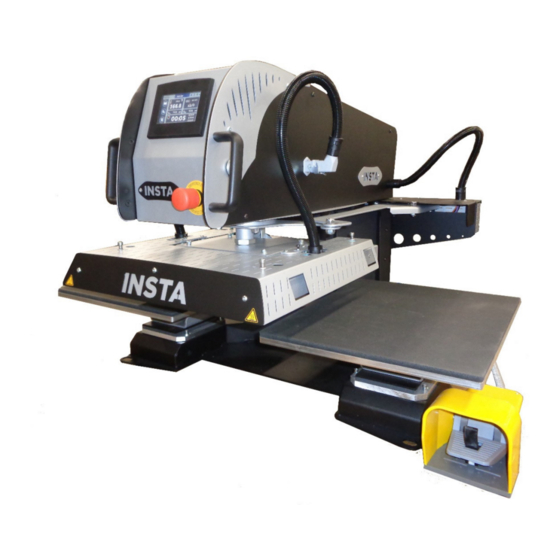
- Page 1 MNL90780 Rev. - 02.11.2020 MODEL 780 OPERATION AND MAINTENANCE MANUAL...
-
Page 2: Safety Summary
Safety Summary WARNING In case of power cord damage, do not attempt to repair or replace the power cord. Contact the manufacturer or the local distributor. WARNING Hot surface. Avoid contact. CAUTION The machine is to be operated by one person only. CAUTION To reduce the risk of electric shock and injury to persons, turn the machine off and disconnect the machine from the power supply before servicing and/or cleaning. -
Page 3: International Symbols
International Symbols Power Off Power On Hot Surface Risk of Electrical Shock Protective Earth Terminal Ground Wet Conditions Start Action Caution – Warning... -
Page 4: General Description
This manual provides the installation, operation, and maintenance procedures for your 780 series machine, as well as easy to follow instructions for on-the-spot maintenance. Your model 780 machine will have a long, trouble-free life. Read this manual. Keep it with your machine; it’s your key to proper operation and lasting service. - Page 5 This warranty does not apply to any machine that has been subjected to misuse, negligence, or has been damaged accidentally or intentionally. Insta shall not be liable for the injury, loss, or damage, directly or indirectly, arising from the use or the inability to use the product.
-
Page 6: Specifications
Specifications Machine Weight (Dry) 425 lbs 450 lbs Shipping Weight (Dry) Height 30 inches Depth 40 inches Width 42 inches Dimensions of the plate 400 x 500 mm 220/240 V Single phase + Ground 50/60 Hz Power supply Power 3300 W Amperage Electronic temperature controller Accurate to... - Page 7 Features This heat-press machine has been designed for intensive production by an operator working in front of the machine. Pneumatic supply connection Power supply Touchscreen Hood + Relay + Fuses Automatic rotation cylinder Heating plate Emergency stop Foot Pedal Silicone foam Removable lower plates...
-
Page 8: Important Points
Otherwise, the company INSTA graphics systems will release all responsibilities on possible problems related to the said machine. THIS DEVICE IS DESIGNED TO BE USED BY ONE USER... -
Page 9: After An Emergency Stop
In order to restart the nominal operation, check if there are any other problems on the machine. Unlock the emergency stop by turning the red part: the machine will reset automatically. Manual It is provided during the delivery of the machine, technical documentation on the components used. Please read it before handling the INSTA machine. -
Page 10: Installation Of The Machine
2. INSTALLATION OF THE MACHINE USE BY QUALIFIED PERSONNEL Do not handle the machine by the trays! 780 MODEL, 230 VOLT Use a designated 16 Amp AC circuit. Only industrial extension cords with proper wire size (2.5 mm ) shall be used. - Page 11 e. Center the machine between the two plates. Position the transport bars and handle the machine only by them. Warning! Do not lift the machine by the trays. g. Hold the machine on a stable and level table by manipulating it with the transport bars. Position and secure the bottom plates if it is not done.
- Page 12 3. START-UP Supply compressed air to the machine. The compressor must provide at least 58 psi - 4 bars. Power the machine with the supplied power cord. Position the button on the back of the stem to "1" and check that the emergency stop button on the front of the stem is unlocked.
- Page 13 Power cord is equipped with a locking system to avoid disconnecting it during operation. Pneumatic network connection Filter Main Power Switch Electrical connection 230VAC-20A Turn on the machine by flipping the main switch on the back of the machine. The touch screen will display the following start page:...
-
Page 14: Control Panel
4. CONTROL PANEL 1) Measured temperature and temperature setting (0 to 220 ° C): The numbers are when the temperature is above the set value Blue when the temperature is below the set value c. White when the temperature is at the set value 2) Time 3) Name of active recipe 4) Status bar (Heat –... - Page 15 The green start buttons and foot pedal allow the start of the pressing cycle. This action is only possible on this screen. For shutdown, there are two modes: 1) STOP button : The heating plate goes up and the press stops moving. 2) Press the Foot Pedal or green button: the plate goes up, moves to the opposite position and stops.
-
Page 16: Description Of The Operating Cycle
Mode Semi-Auto (pedal) Mode Auto c) Rotation Speed Contact your official INSTA distributor to adjust this setting. 6. DESCRIPTION OF THE OPERATING CYCLE Move the upper platen to the opposite side of where you want to work. Test by pressing the pedal or the green push button to validate your choice. - Page 17 7. PARAMETERS a) Status bar The status bar allows you to know the status of the machine on any activated page. Logo Time Active Recipe Heat status – Cycle – Eco – Warning Heating status: Blue flake = Stop Red flame = On. Blinks between the two states in regulation. Cycle : Machine ready to work.
- Page 18 c) Recipes The system is designed to receive up to 6 different recipes. Each recipe can be renamed with 16 characters. You can access the appointment page for recipes and choice of regulation as follows: The recipe store : The name The type of regulation 4 different timers 2 differents pressure...
- Page 19 d) Setting menu and diagnosis Push the button on the left of the screen to access the settings. Click on the desired menu to access it. Press the arrow on the bottom right to get out. Settings (Buzzer, timers, etc.) ECO Modes (2 pages) Firmware information Time...
- Page 20 e) Ergonomics settings (1) Buzzer ON/OFF = Disables or activates the buzzer when touching the screen and at the end of the cycle. The buzzer remains operational in the event of a fault (5 rings). (2) Buzzer « End of cycle » ON/OFF = ring 2 seconds before the end of the cycle. (3) Access to the page "Rotation - temperature range"...
- Page 21 automatic mode, it stops at the set time. The program displays the idle page to indicate that it is paused. The brightness decreases and oscillates slightly. This mode also allows an early start of the heating, for example before taking post. For this, it is necessary to leave the machine under tension. (1) Extended standby mode ON / OFF.
- Page 22 Regarding the temperature, in eco mode, it is impossible to ask for a lower temperature than the set point of the current recipe. In standby mode, it is impossible to ask for a temperature higher than the temperature of the eco mode.
- Page 23 h) Information Manufacturer – Firmware version. i) Factory settings Change the factory settings, vital settings for the machine. Changing them voids the warranty. Enter the password in the field dedicated : Additionnal pretected access Offset Setting Factory setting...
- Page 24 8. DIAGNOSIS To know the status of the inputs / outputs of the PLC. On this page all operating cycles are possible by pressing the pedal and the green buttons. Shutdown possible by button touch : No action possible. This screen is used for troubleshooting and evaluating sensor and actuator states. The support service can ask the operator to display it during a telephone intervention for example.
- Page 25 a) Alarms and warnings If a fault is detected, the machine is in STOP mode Following screen is diplayed : Press the red area to acknowledge the fault and the job page is displayed. If an event is detected, the machine is Waiting Following screen is diplayed : Press the orange area to acknowledge the fault and the job page is displayed.
- Page 26 b) Summary Alarms-Events If the problem that caused the fault (faulty sensor, lack of air, temperature problem) is solved, the fault light goes out automatically. : Removes unpaid defects that are no longer in progress (repair done). If this support is not enough, stop and restart the machine (press the emergency stop). List of alarms / events : Active fault Inactive fault...
- Page 27 Alarm 06 : Pressing lower sensor not Signal not detected after 5 seconds. Result of sensor reached failure, lack of compressed air supply, mechanical lock, ...). Alarm 8 : Right sensor rotation not Signal not detected after 5 seconds. Result of sensor achieved failure, lack of compressed air supply, mechanical lock, ...)
- Page 28 9. OPERATING CYCLE a) Operating mode The MS 780 can operate according to 3 cycle variants: Semi-automatic pedal mode: after pressing the pedal, the stem changes its position and presses. Single post mode: After pressing the pedal, the stem changes its position, presses, and returns to the starting plate.
- Page 29 c) Automatic pressure It is possible to change automatically the pressure between two stations. It’s independent of number of timers. If work needs only one pressure, sets the same value on the two stations. Find the settings on next page: 1) Left pressure –...
- Page 30 IMPLANTATION OF EQUIPMENT Pressing cylinder Pressing electro valve Check valve Cylinder stopper mounted on cylinder bottom port Rotation regulator Rotation Electro valve Left sensor Rotation cylinder Right sensor Interior of the gallows Back of the machine (DUPLEX PRO & DUPLEX AIR PRO)
- Page 31 Press Cylinder Limit switch up magentic Limit switch sensor down magnetic sensor Communs 24VDC 0VDC Green push button Front...
- Page 32 Note: the front facade tilts leaving the 2 Automatic bottom screws Manometer Emergency stop Automatic pressure valve USB cable connector (not Buzzer included) PLC-HMI Inside the top cover...
- Page 33 Laser option Switch ON-OFF Power supply 220VAC Power supply 230V Foot switch connection Protection fuse Power supply 24 VDC 230V-24V Security relay Heating plate Protection fuse static relay 230 VAC...
-
Page 34: Electrical Diagram
ELECTRICAL DIAGRAM... -
Page 35: Pneumatic Diagram
PNEUMATIC DIAGRAM... -
Page 36: Maintenance
Contact your dealer to evaluate their change or repair. 2. MAINTENANCE Insta heat presses are virtually maintenance-free. To ensure proper operation, follow the precautions listed below: Do not heat objects that could damage or cut the silicone mat or damage the teflon coating of the heating plate. - Page 37 PIECES SUBJECT TO WEAR When ordering: specify the description, the reference and the quantity. Reference Description Quantity ELECTRICAL PARTS AUT-SM43 PLC IHM SON-PT100 3V TEMPERATURE SENSOR UL MICA RESISTANCE 400x500 3200W RES-500x400-3200W-UL PNEUMATIC PARTS VER-SM25 AIR CYLINDER Ø125 C100 VER-SM23 AIR CYLINDER Ø40 C200 FIL-013 AIR FILTER...
- Page 38 QUICK RESPONSE TIPS All maintenance repairs must be done at standstill and machine recorded (electrical and pneumatic energy stopped). The heating plate can cause burns. The operator must ensure that the temperature of the plate is below 77 ° F / 25 ° C on the display, before any manipulation. SYMPTOMS POSSIBLE TROUBLES TROUBLESHOOTING...
- Page 39 13925 E. 166 St. ● Cerritos, CA USA 90702 ● (800) 421-6971 ● Fax (562) 404-3010 Parts Orders ● (800) 426-3609 ● (562) 404-3000 Ext. 215 Technical Support ● (800) 426-3609 ● (562) 404-3000 Ext. 208 In-House Repair ● (800) 426-3609...
Need help?
Do you have a question about the 780 and is the answer not in the manual?
Questions and answers