Table of Contents
Advertisement
Quick Links
Advertisement
Table of Contents

Related Manuals for Marco FRIIA Lite


Summary of Contents for Marco FRIIA Lite
- Page 1 Instruction Manual FRIIA LITE Machine P/N: 1000201#, 1000202#...
-
Page 2: Table Of Contents
User manual User manual It is highly recommended to fit a water regulator to the supply feed. In the event of mechanical failure a regulator set correctly will ensure the water supply is cut. Marco suggests 10 litres continuous flow. Accessories Part no. -
Page 3: Introduction
Introduction The information provided in this manual is intended to assist in the installation and maintenance of the Marco FRIIA Lite System. Please read the instructions carefully to prevent accidents and ensure an efficient installation. This manual is not a substitute for any safety instructions or technical data affixed to the machine or its packaging. -
Page 4: Chiller Specification
1. Chiller Specification Model 1000201 1000202 Description FRIIA Lite Chiller FRIIA Lite Chiller/Carbonator Power Supply Voltage & Frequency (V/Hz): 230V ~ 50/60Hz 220-240V ~ 50/60Hz Power Consumtion: 177W 220W Colling capacity: >12 L/h ( ΔT ≥ 10°C ) >12 L/h ( ΔT ≥ 10°C ) Pouvoir Hydrogène PH... -
Page 5: Safety
Do not run any other liquid besides water through the system. • If you believe the system to be damaged, contact Marco Beverage Systems. If the inlet hose is damaged, it must be replaced with an new inlet hose-set compliant to EN 61770 or IEC 61770. - Page 6 DANGER EXTERNAL GAS CYLINDER LOCATION To prevent the risk of injury or damage, the CO2 cylinder must always be kept in a vertical position against a wall, held in place by a chain fixed to a bracket. Do not expose the bottle to heat sources or very low temperatures.
- Page 7 WARNING WATER SUPPLY Connect the water dispenser exclusively to a line of drinkable water supply. WARNING WATER SUPPLY In order to avoid accidental flooding due to losses that may occur on the water supply line, external or internal device it is necessary to install the appropriate anti-flooding valve “WATER BLOCK” (not included in the unit).
-
Page 8: Basic Installation
3. Basic Installation 3.1 UNPACKING INSTRUCTIONS •The chiller must be handled only in a vertical position. Transporting the appliance in a horizontal position can cause severe damage to the refrigerator. •If the chiller arrives in a horizontal position, leave to sit for 3-4 hours in the verticle position before turning the chiller on. •Remove the exterior and interior packing. -
Page 9: Co2 Installation
There are different type of CO2 cylinder available. Always use a pressure reducer suitable for the type of valve on the cylinder. If you use CO2, especially in a small area, ventilate the contaminated area at once. We advise using a Dual gauge CO2 regulator, Marco part number 1400195. Check for leaks using a solution of soapy water. Recommended CO2 Regulator... -
Page 10: Operation
3.5 BACKFLOW PREVENTION This chiller must be installed with adequate backflow protection to comply with all applicable federal, state and local codes. 3.6 ENVIRONMENTAL CONDITIONS • The equipment is not suitable for external use. • The equipment must be placed so it is protected from rain and water splashes, and in a location with the temperature appropriate to its climate class (stated in specification);... - Page 11 4.2 MAINTENANCE Maintenance procedures (described below) are required for optimum equipment operation. 4.2.1 DAILY MAINTENANCE 1. The font. Clean the font nozzle and remove any residue using warm water; do not use solvents or abrasive detergents. If required, remove any scale with a food descaling solution. 2.
-
Page 12: Friia Lite Installation Guide
5. FRIIA Lite Installation Guide Font Positioning... - Page 13 FRIIA Font Counter Cut Out Check scale of template 32mm before cutting. Scale 1:1 / 1 ¼” 100mm / 4” For drip tray only...
- Page 14 Recommended Plumbing...
- Page 15 Chiller Installation Electrical Connection 1/4” Cold Output to Font Electrical Connection to Font to Boiler (Cable Supplied with Font) Filter & CO2 Cord socket Hatch Cooling Switch (Compressor on) Water In (3/8”) CO2 Connection (8mm tube)
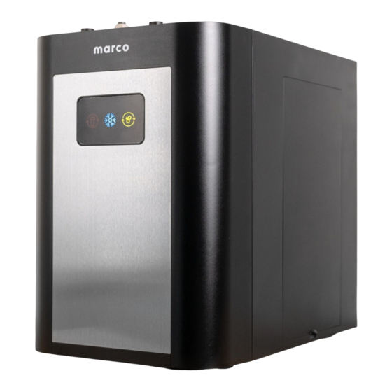
- Page 16 Chiller Screen Icons Sparkling & Cold model Cold only model Icon Description Filter Light Lights up to indicate the filter needs to be replaced. Flashing indicates a shortage of water. Cooling Light Lights up to indicate the chiller is ready to use (allow 70 - 120min for the chiller to get down to temperature).
- Page 17 Boiler Installation The boiler paired with the chiller is the MIX Boiler UC3 (p/n. 1000880). For more details on boiler installation please consult boiler instruction manual.
- Page 18 Font Installation 1. No Drip Tray 32mm / 1 ¼”...
- Page 19 Font Installation 2. Drip Tray (sold seperately p/n. 2300268) 32mm/ 1 ¼” 100mm/ 4” The drain outlet to the drip tray should be plumbed to waste...
- Page 20 Connecting Hoses (8mm) COLD VENT (1/4”) ELECTRICAL (FONT CONNECTION) CHILLER TO BOILER CONNECTOR (1501180) Hot Water Cold Water Power 1/4” Vent Vent connects to boiler vent outlet...
- Page 21 Cabinet Ventilation Please Note: In all cases remove the back panel from the cabinet. Front ventilation Side ventilation Base ventilation Ventillation grilles cut out of Ventillation grilles cut out of standard Ventilation grilles cut in base standard cabinet door. 600mm cabinet. Grilles may be fitted on panel and base plinth, a grille either side as long as they ventilate into must also be cut out at the top...
- Page 22 Cabinet Ventilation Fan Installation Exhaust fan Exhaust fan Intake fan Intake fan (optional) (optional) Exhaust fan Exhaust fan...
-
Page 23: Sanitsation And Cleaning
2. Turn the compressor off by turning off the cooling switch at the back of the machine 3. Replace the filter cartridge with a sanitising filter recommended by Marco and fill with clean water and with sanitising fluid in the concentration and contact time recommended by the manufacturer. - Page 24 6.3 Maintenance 1. Keep the chiller in a dry and cool place and avoid direct sunshine. Never put the chiller on paper or foam, which may store water and then cause creepage. Do not place flammable objects near the chiller. Do not use the machine outdoors or where it may be splashed by water.
-
Page 25: Troubleshooting
7. Chiller Troubleshooting Cold & Sparkling Model ● Illuminated Flash ○ Product 1000202 Filter Cooling Cylinder Cause Solution -RED -BLUE -YELLOW Power ON + Cooling ON + Cylinder ○ ○ Normal FULL Power ON + Cooling ON + Cylinder ○ ●... - Page 26 Cold Only Model Product 1000201 Filter - Cooling - Cause Solution Blue Power ON + Cooling ○ Normal Power ON + Cooling ○ ● Normal Finished Filter reminder + Cool- ● Filter needs replacing Replace the filter,reset the filter ing ON recovery button (located beside filter) Filter reminder + Cool-...
- Page 27 Failure Cause Solution Low water pressure Check the tap water Filter not replaced in time, beyond the use Replace the filter time Over consumption of water in a short time Wait a moment, and water is available again Unsuitable water temperature Turn on the cooling switch at the rear of the The cooling switch is not turned on...
- Page 28 Marco Beverage Systems Limited, 74 Heather Road, Sandyford Business Park, Dublin 18, Ireland Tel: 00353 (0) 1 295 2674 Email: sales@marcobeveragesystems.com...
Need help?
Do you have a question about the FRIIA Lite and is the answer not in the manual?
Questions and answers