Table of Contents
Advertisement
SERVICE MANUAL
FRIIA RANGE:
•
1000861* – FRIIA Chiller/Carbonator
•
1000860* – FRIIA Chiller
* regional variance
Marco Beverage Systems Ltd.
74 Heather Road,
Sandyford Business Park,
Dublin 18,
Ireland
Tel Ireland:
00353 (0) 1 295 2674
Tel UK:
0044 (0) 1933 666 488
Tel US:
206 641 7692
Email:
sales@marco.ie
Advertisement
Table of Contents
Troubleshooting

Subscribe to Our Youtube Channel
Related Manuals for Marco FRIIA Series


Summary of Contents for Marco FRIIA Series
- Page 1 SERVICE MANUAL FRIIA RANGE: • 1000861* – FRIIA Chiller/Carbonator • 1000860* – FRIIA Chiller * regional variance Marco Beverage Systems Ltd. Tel Ireland: 00353 (0) 1 295 2674 74 Heather Road, Tel UK: 0044 (0) 1933 666 488 Sandyford Business Park,...
-
Page 2: Table Of Contents
CONTENTS: INTRODUCTION MANUFACTURER IDENTIFICATION SAFETY INSTRUCTIONS BASIC INSTRUCTIONS Installation Details Green LED Troubleshooting Maintenance Routine maintenance Check for CO2 pressure Cleaning the chiller condenser Sanitizing Cleaning Cautions and safety tips 5. TECHNICAL DATA General Description External Arrangement R290 Refrigerating circuit Overview Servicing R290 Equipment R290 Refrigerant circuit... -
Page 3: Introduction
All information in this manual is current at the time of publication and is subject to change without notice. Only technicians or service providers authorised by MARCO should carry out installation and maintenance of these machines. -
Page 4: Manufacturer Identification
This version of the use and Maintenance Manual describes the characteristics of the standard production equipment as of the date of printing. Contact Marco Beverage Systems for any technical queries or to order spare parts. When replacing equipment parts, you are advised to use original spare parts;... -
Page 5: Safety Instructions
Allow to cool before removing components. • The use of spares and accessories not recommended by Marco may cause damage and/or injuries. • Do not use outdoors. Do not place on or near a hot gas or electric burner. -
Page 6: Basic Instructions
4. BASIC INSTRUCTIONS: 4.1. INSTALLATION DETAILS: Positioning • The equipment must be placed on a surface capable of bearing the weight of the chiller complete with water. Install the equipment following the schematic described in this user guide. • The chosen position must in any case allow satisfactory ventilation; in particular, there must be a gap of at least 10 cm (3.9 in) around the back and top for ventilation. - Page 7 Backflow prevention • This equipment must be installed with adequate backflow prevention to comply with all applicable federal, state and local codes. • NSF compliant version already integrates a backflow prevention device ASSE1032 certified with a dedicated 100 mesh strainer; both devices are enclosed in a stainless steel frame with dedicated hydraulic fittings.
- Page 8 CO2 installation procedure Connect CO2 using the appropriate 8mm polyethylene tube. CO2. • Only use super-dry food grade CO2. Before connecting the pressure reducer to the gas cylinder, always vent any dirt from the valve and close the cylinder valve after few seconds.
- Page 9 Thermostat setting • The temperature of the dispensed beverages can be adjusted using the thermostat on the back of the chiller. • To avoid an accidental change of the set point, the thermostat is protected by a tamper protection; remove the protection to access the thermostat knob. •...
- Page 10 Operating chiller for the first time: • Before connecting the appliance to the power source, let it stand upright for approximately 2 hours. This will reduce the possibility of a malfunction. • Check that all installation procedures have been carried out. •...
-
Page 11: Green Led Troubleshooting
4.2 GREEN LIGHT TROUBLESHOOTING: After about 3.5 minutes of continuous carbonation pump operation, without the usual stops and starts dictated by the carbonation level probes the internal carbonation pump controller shuts carbonation pump and LED starts blinking. Refer to Troubleshooting chapter of this manual for corrective actions. 4.3 MAINTENANCE: 4.3.1 ROUTINE MAINTENANCE: To always ensure good equipment operation, certain maintenance procedures (described... -
Page 12: Check For Co2 Pressure
4.3.2 CHECK FOR CO PRESSURE: Review pressure CO2 gauges for proper settings. DANGER ELECTRICAL MAINS Always isolate chiller from power supply before doing any work on it, to prevent damage and health hazards. Replacing a carbon dioxide (CO2) cylinder When the needle of the reducer high pressure gauge is in the red segment, the cylinder needs replacing: 1. -
Page 13: Sanitizing
This procedure should only be carried out by persons trained by Marco Beverage Systems or their approved distributors. The operation of higienization/sterilization has to be carried out every time the refrigerator is installed and: - every 6 months when it is used. - Page 14 SANITIZING 1. Turn off Electrical Power Supply. 2. Replace the filter cartridge with a sanitizing filter recommended by Marco Beverage Systems and fill with clean water and with sanitizing fluid in the concentration and contact time recommended by the manufacturer.
-
Page 15: Cleaning
4.3.5 CLEANING: DANGER ELECTRICAL MAINS Always isolate chiller from power supply before doing any work on it, to prevent damage and health hazards. The exterior of these machines may be cleaned with a damp cloth and a light detergent. Do not use abrasive cloths or creams, as this will spoil the finish of the machine. -
Page 16: Technical Data
5. TECHNICAL DATA: 5.1 GENERAL DESCRIPTION: FRIIA Specifications Max Dimensions (W/D/H) Width: 259 mm Depth: 436 mm Height: 457 mm (w/feet and Overpressure valve) Voltage and frequency ratings 230 V/50 Hz 110V/60 Hz Max Power consumption 200 W Compressor nominal power 1/8 HP Refrigerant type and quantity R290 / 45 gr... -
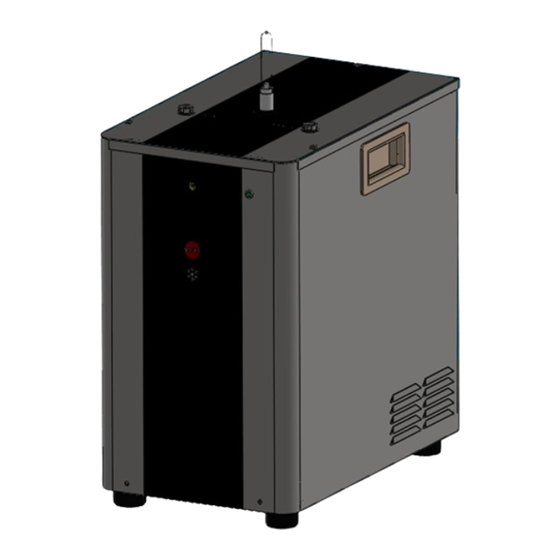
Page 17: External Arrangement
5.2. EXTERNAL ARRANGEMENT: Boiler Font Outer lid connection connection. Handles Surround PR Valve “Power On” Green LED Service Push button Front label Feet FRIIA Service manual Page 17... -
Page 18: R290 Refrigerating Circuit
• Refrigerant charge in an R290 system is 40 – 60% less than an equivalent R134A system. • Only Marco technicians or service providers trained on procedures for handling R290 refrigerant gas can carry out repairs on the chillers charged with R290. -
Page 19: R290 Refrigerant Circuit
5.3.3 R290 Refrigerant circuit What are R290 refrigerant circuit components? • Compressor and copper pipes welded on the compressor; • Priming pipe • Suction pipe • Filling pipe with its cap. • Condenser and condenser pipes, priming pipe from compressor and filter pipe to filter/drier. -
Page 20: Access To Internal Components
6. ACCESS TO INTERNAL COMPONENTS: To inspect the chiller from the top: 1. Disconnect the machine from the electrical supply. 2. Disconnect all water and CO2 connectors. 3. Purge the CO2 from the machine. 4. Allow to cool sufficiently. 5. Remove the outer lid. To remove outer lid, undo 3 Phillips Screws. 6. - Page 21 To access to internal components. 1. Disconnect the machine from the electrical supply. 2. Allow to cool sufficiently. 3. Remove the outer lid. To remove outer lid, undo 3 Phillips Screws. 4. Remove surround, To remove surround, undo 2 Phillips Screws on front and 4 on back. Place the panels to the side of the machine.
- Page 22 Inlet Pressure Regulator Sporadically, dust or iron particles from the outer tubes during the first installation and during maintenance operations to external filters can clog the regulator. To replace the pressure regulator, disconnect inlet and outlet tubes and undo the 2 screws (a,b) located on the backside of the chiller.
- Page 23 Carbonation Pump To replace the carbonation pump, disconnect the black wirings from the carbonation control module, loosen the 2 screws (c,d) located on the right side of the pump auxiliary bracket and remove the 2 screws on the left side (a,b); the pump can now be removed for maintenance.
- Page 24 Carbonation Pump Electronic Control Unit To replace the carbonation pump ECU, disconnect the wirings from the ECU, and undo the screw (a) located on the top side of the bracket; the ECU can be removed for maintenance. During removal, be careful not to damage the electric wiring or the refrigeration group pipes.
- Page 25 Dispense Solenoid Access: To access the dispense solenoid(s), the solenoid bracket need to be removed. Unscrew the four Phillips screws holding the bracket. If the dispense solenoid(s) need to be replaced unscrew the two Phillips screws holding the solenoid in place and remove tubing from solenoid body. During removal, be careful not to damage the electric wirings, refrigeration group pipes and water circuit pipes.
- Page 26 Electronic PCB access Remove the lid of the chiller. Remove the PCB enclose lid by undoing two screws (a,b) this will give access to the PCB. Carefully remove the electrical connectors, do not apply too much force to avoid damage. Remove the PCB by undoing the 4 screws (c) located on the PCB itself.
- Page 27 Compressor PCB, PRV valve access for replacement To access the compressor PCB and/or the PRV the top bracket needs to be removed. To remove the internal top bracket sub-assembly with all components assembled on it (Electronic Control Unit and PRV), remove the 2 screws (a,b) located on the back of the panel and (c,d, e, f) located on the two corners of the top bracket.
- Page 28 Pressure Relief Valve access and replacement Please ensure the CO2 is disconnected and purged from the machine. To remove the PRV, firstly remove the tubing from hydraulic fitting and afterwards undo the fitting (a) from the PRV. Carefully unscrew the PRV bolt (b) from the bracket and repair or replace the valve. During removal, be careful not to damage the electric wirings, refrigeration group pipes and water circuit pipes.
- Page 29 Pressure Relief Valve cleaning and replacement In case of leakage from PRV, the movable plunger can be easily remove for check and cleaning. Please ensure the CO2 is disconnected and purged from the machine. This can be done without removal of the outer lid; simply keep the PRV with a pliers simply hold the steel valve body (a) in place while at the same time unscrew the plastic body of the PRV by acting on the cylindrical part (b).
- Page 30 Carbonator NRV cleaning and replacement (CO2 in cold still water) Sporadically, dust or iron particles may be present in the pipes or coils of the chiller or may come from the outer tubes during the first installation or during maintenance operations to external filters.
-
Page 31: Troubleshooting - Diagnostic Guide
It is normal that the appliance works at a continuously high room temperature Gas leak from the cooling system Contact a specialized technician (refrigerator repairman) or The compressor Marco Beverage Systems works continuously, but the water is not The compressor is faulty Check wirings and voltage on compressor terminals and cold replace the faulty component if needed. - Page 32 ISSUE PROBABLE CAUSE SOLUTION pressure too low Restore correct CO pressure (typically about 4 bar / 60 psi) cylinder empty Replace CO cylinder Too low CO volume Water temperature too high because cooling capacity is See refrigeration/equipment specifications vs. volume exceeded by over drawing requirements and reduce amount of glasses taken per given time of install higher volume unit.
-
Page 33: Wiring Diagram
8. WIRING DIAGRAM: FRIIA Service manual Page 33... -
Page 34: Hydraulic Circuit
9. HYDRAULIC DIAGRAM: FRIIA Service manual Page 34... - Page 35 Functional Hydraulic Schematic FRIIA Service manual Page 35...
-
Page 36: Installation Diagram
10. INSTALLATION DIAGRAM: 1. REAR WATER INLET 10. CARBONATOR 2. STOP VALVE H 11. TOP SPARKLING WATER OUT 3. FILTER H 12. TOP COLD STILL WATER OUT 4. WATER INLET LINE 5. CO CYLINDER 6. CO PRESSURE REDUCER 7. CO INLET TUBING 8. -
Page 37: Exploded View
11.2 Outer frame: FRIIA Service manual Page 37... -
Page 38: Top Bracket
11.3 Top bracket: FRIIA Service manual Page 38... -
Page 39: Front Electronic Bracket
11.4 Front electronic bracket: FRIIA Service manual Page 39... -
Page 40: Pump Bracket
11.5 Pump and Electrovalve brackets: FRIIA Service manual Page 40... -
Page 41: Base
11.6 Base : FRIIA Service manual Page 41... -
Page 42: Spare Parts
CABLES AND HARNESSES 115Vac FRIIA Service manual Page 42... - Page 43 FRIIA Service manual Page 43...
- Page 44 FRIIA Service manual Page 44...
- Page 45 FRIIA Service manual Page 45...
- Page 46 FRIIA Service manual Page 46...
Need help?
Do you have a question about the FRIIA Series and is the answer not in the manual?
Questions and answers