Sony TCM-40DV Service Manual
Hide thumbs
Also See for TCM-40DV:
- Operating instructions (2 pages) ,
- Operating instructions (2 pages) ,
- Service manual (14 pages)

Related Manuals for Sony TCM-40DV


Summary of Contents for Sony TCM-40DV
- Page 1 TCM-40DV SERVICE MANUAL US Model Canadian Model Ver 1.0 1999. 04 AEP Model E Model Model Name Using Similar Mechanism TCM-36 Tape Transport Mechanism Type MT-40-118 SPECIFICATIONS CASSETTE-CORDER MICROFILM...
-
Page 2: Table Of Contents
SECTION 1 SERVICING NOTES TABLE OF CONTENTS In this set, the S102 (POWER) detects REC/PLAYBACK on. It is mounted on the MAIN board, and therefore the REC/PLAY- BACK on cannot be detected with the MAIN board removed. SERVICING NOTES ..........2 When making an operation check and voltage check of mechani- cal deck with the MAIN board removed, fix the S102 at turn on. -
Page 3: General
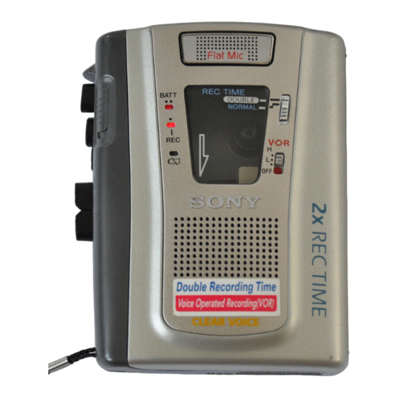
SECTION 2 This section is extracted from instruction manual. GENERAL • Location of Controls TAPE COUNTER Flat mic Micropohone plat REC TIME r REC p STOP BATT/REC/ i 9 PLAY SPEED CONTROL 0 REW/REVIEW ) FF/CUE PAUSE c DC IN 3 V –... -
Page 4: Disassembly
SECTION 3 DISASSEMBLY • This set can be disassembled in the order shown below. Cabinet (Rear), Cassette Lid MAIN Board, Mechanism Deck Belt (MT-40-118) Note: Follow the disassembly procedure in the numerical order given. CABINET (REAR), CASSETTE LID 8 cassette lid 7 boss 9 cassette spring 3 claw... - Page 5 MAIN BOARD, MECHANISM DECK (MT-40-118) Note: On installation MAIN board adjust the S105 6 three screws and button (pause). (IB lock) 7 claw button (pause) 8 mechanism deck (MT-40-118) 1 Remove four solders of motor leads (M901). S105 5 MAIN board 3 screw 2 Remove the two solders 4 screw...
-
Page 6: Mechanical Adjustments
SECTION 4 MECHANICAL ADJUSTMENTS BELT 1. Clean the following parts with a denatured-alcohol-moistened swab: record/playback head pinch roller 1 capstan belt erase head rubber belt capstan 2. Demagnetize the record/playback head with a head demagne- tizer. (Do not bring the head demagnetizer close to the erase 2 FR belt head.) 3. -
Page 7: Electrical Adjustments
TCM-40DV SECTION 5 SECTION 6 ELECTRICAL ADJUSTMENTS DIAGRAMS Setting: Tape Speed Adjustment 6-1. BLOCK DIAGRAM • Supplied voltage: 2.5 V Mode: playback • Switch and control position • SIGNAL PATH MIC101 test tape VOL contorl (RV401) : mechanical center (MIC) -
Page 9: Schematic Diagram
TCM-40DV 6-3. SCHEMATIC DIAGRAM • See page 17 for IC Block Diagrams. Note on Schematic Diagram: • All capacitors are in µF unless otherwise noted. pF: µµF 50 WV or less are not indicated except for electrolytics and tantalums. • All resistors are in Ω and W or less unless otherwise specified. -
Page 10: Exploded Views
SECTION 7 EXPLODED VIEWS • IC Block Diagrams IC601 LB1877V-TLM NOTE: (2) MECHANISM DECK SECTION-1 • -XX and -X mean standardized parts, so they • Items marked “*” are not stocked since they (MT-40-118) IC101 LA4168ML-TE-L may have some difference from the original are seldom required for routine service. - Page 11 (3) MECHANISM DECK SECTION-2 (MT-40-118) supplied supplied HE901 Ref. No. Part No. Description Remark Ref. No. Part No. Description Remark 3-321-483-11 RING, RETAINING (0.25) 3-035-368-01 SPRING (PR2), TORSION 3-701-437-51 WASHER 3-924-684-01 SPRING (LOCK PLATE), TENSION X-3372-171-1 FLYWHEEL ASSY 3-924-619-01 LEVER (SW) 3-924-623-01 LEVER (PLAY) 3-924-639-01 LEVER (CR) 3-924-621-01 LEVER (REW)
-
Page 12: Electrical Parts List
SECTION 8 MAIN ELECTRICAL PARTS LIST NOTE: When indicating parts by reference • Due to standardization, replacements in the • Items marked “*” are not stocked since they number, please include the board. parts list may be different from the parts speci- are seldom required for routine service. - Page 13 MAIN Ref. No. Part No. Description Remark Ref. No. Part No. Description Remark D603 8-719-404-50 DIODE MA111-TX R112 1-216-071-00 METAL CHIP 8.2K 1/10W R113 1-216-081-00 METAL CHIP 1/10W < FERRITE BEAD > R114 1-216-065-00 RES, CHIP 4.7K 1/10W R116 1-216-089-00 RES, CHIP 1/10W FB101 1-414-235-22 FERRITE...
- Page 14 TCM-40DV MAIN Ref. No. Part No. Description Remark Ref. No. Part No. Description Remark RV606 1-238-663-11 RES, ADJ, CARBON 4.7K < SWITCH > S101 1-771-321-11 SWITCH, SLIDE (REC/PB) S102 1-771-092-21 SWITCH, PUSH (1 KEY) (POWER) S105 1-572-922-11 SWITCH, SLIDE (PAUSE c) <...
Need help?
Do you have a question about the TCM-40DV and is the answer not in the manual?
Questions and answers