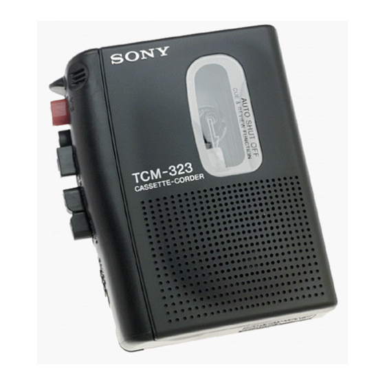
Sony TCM-323 Service Manual
Hide thumbs
Also See for TCM-323:
- Operating instructions manual (6 pages) ,
- Operating instructions (2 pages) ,
- Operating instructions (2 pages)
Advertisement
SERVICE MANUAL
Ver 1.2 2004.03
Sony Corporation
9-923-304-12
2004C05-1
Personal Audio Company
© 2004.03
Published by Sony Engineering Corporation
TCM-323
Model Name Using Similar Mechanism
Tape Transport Mechanism Type
SPECIFICATIONS
US Model
Canadian Model
AEP Model
E Model
NEW
MT-323-118
CASSETTE-CORDER
Advertisement
Table of Contents

Related Manuals for Sony TCM-323


Summary of Contents for Sony TCM-323
- Page 1 TCM-323 SERVICE MANUAL US Model Canadian Model Ver 1.2 2004.03 AEP Model E Model Model Name Using Similar Mechanism Tape Transport Mechanism Type MT-323-118 SPECIFICATIONS CASSETTE-CORDER Sony Corporation 9-923-304-12 2004C05-1 Personal Audio Company © 2004.03 Published by Sony Engineering Corporation...
-
Page 2: Table Of Contents
SECTION 1 SERVICING NOTES TABLE OF CONTENTS In this set, the S102 (power) detects REC/PLAYBACK on. It is mounted on the MAIN board, and therefore the REC/PLAY- BACK on cannot be detected with the MAIN board removed. SERVICING NOTES ..........2 When making an operation check and voltage check of mechani- cal deck with the MAIN board removed, fix the S102 at turn on. -
Page 3: General
SECTION 2 This section is extracted from instruction manual. GENERAL – 3 –... -
Page 4: Disassembly
SECTION 3 DISASSEMBLY • This set can be disassembled in the order shown below. MAIN BOARD, MECHANISM DECK (MT-323-118) CABINET (REAR), CASSETTE LID BELT Note: Follow the disassembly procedure in the numerical order given. CABINET (REAR), CASSETTE LID 9 cassette lid 7 boss 8 cassette spring 6 Remove the two solders... - Page 5 MAIN BOARD, MECHANISM DECK (MT-323-118) 5 three screws (IB lock) 6 claw 7 mechanism deck (MT-323-118) 1 Remove the two solders electret condenser microphone (MIC901). 1 Remove the two solders motor (M901). 4 MAIN board 1 Remove the two solders 3 screw magnetic head (HRP901).
- Page 6 INSTALLATION MAIN BOARD On installation MAIN board, adjust to the S101 and the S102. screw (1.7) screw (M1.4) MAIN board S102 (POWER) S101 (REC/PB) lever (REC) – 6 –...
-
Page 7: Mechanical Adjustments
SECTION 4 MECHANICAL ADJUSTMENTS 1. Clean the following parts with a denatured-alcohol-moistened swab: record/playback head pinch roller erase head rubber belt capstan idlers 2. Demagnetize the record/playback head with a head demagne- tizer. (Do not bring the head demagnetizer close to the erase head.) 3. -
Page 8: Electrical Adjustments
SECTION 5 ELECTRICAL ADJUSTMENTS Precaution Tape Speed Adjustment • Supplied voltage: 2.5 V • Switch and control position Procedure: PAUSE switch (S105): OFF Mode: playback VOL (RV101): mechanical mid Standard tape for adjusting frequency WS-48A Test Tape counter (3 kHz, 0 dB) 10 k Ω... -
Page 9: Diagrams 6-1. Block Diagram
Ver 1.2... - Page 10 Ver 1.2...
-
Page 11: Schematic Diagram
Ver 1.2... - Page 12 Ver 1.1 SECTION 7 EXPLODED VIEWS NOTE: • -XX and -X mean standardized parts, so they • Items marked “*” are not stocked since they may have some difference from the original are seldom required for routine service. Some one. delay should be anticipated when ordering •...
-
Page 13: Printed Wiring Board
(2) MECHANISM DECK SECTION-1 (MT-323-118) HRP901 HE901 M901 supplied Ref. No. Part No. Description Remark Ref. No. Part No. Description Remark X-3370-386-1 PINCH ROLLER ASSY 3-924-637-01 GEAR (FF) 3-925-146-11 BUTTON (FF) ()) 3-924-673-01 GEAR (S REEL) 3-925-147-01 BUTTON (REW) (0) 3-924-674-01 SPRING (B. -
Page 14: Exploded Views
(3) MECHANISM DECK SECTION-2 (MT-323-118) supplied Ref. No. Part No. Description Remark Ref. No. Part No. Description Remark 3-321-483-11 RING, RETAINING (0.25) 3-924-628-01 LEVER (FR) 3-315-495-31 WASHER 3-924-633-01 SPRING (STOP), TENSION X-3370-384-1 FLYWHEEL ASSY 3-924-622-01 LEVER (STOP) 3-924-623-01 LEVER (PLAY) 3-924-643-01 SPRING (PR), TORSION 3-924-621-01 LEVER (REW) 3-924-684-01 SPRING (LOCK PLATE), TENSION... - Page 15 SECTION 8 MAIN ELECTRICAL PARTS LIST NOTE: • Due to standardization, replacements in the • Items marked “*” are not stocked since they When indicating parts by reference are seldom required for routine service. parts list may be different from the parts speci- number, please include the board.
- Page 16 TCM-323 MAIN Ref. No. Part No. Description Remark R605 1-216-049-11 RES,CHIP 1/10W R606 1-216-073-00 METAL CHIP 1/10W < VARIABLE RESISTOR > RV101 1-223-293-11 RES, VAR, CARBON 50K (VOL) RV601 1-238-663-11 RES, ADJ, CARBON 4.7K < SWITCH > S101 1-572-964-11 SWITCH, SLIDE (REC/PB)
-
Page 17: Electrical Parts List
TCM-323 MEMO – 19 –... -
Page 18: Revision History
TCM-323 REVISION HISTORY Clicking the version allows you to jump to the revised page. Also, clicking the version at the upper right on the revised page allows you to jump to the next revised page. Ver. Date Description of Revision 1998.01...
Need help?
Do you have a question about the TCM-323 and is the answer not in the manual?
Questions and answers