Sony TCM-20DV Service Manual
Hide thumbs
Also See for TCM-20DV:
- Service manual (16 pages) ,
- Specifications (2 pages) ,
- Operating instructions manual (10 pages)
Table of Contents
Advertisement
Quick Links
SERVICE MANUAL
Ver 1.0 2000. 02
Get user manuals:
See SafeManuals.com
Recording system
2-track 1 channel monaural
Tape speed
4.8 cm/s or 2.4 cm/s
Frequency range
250 - 6,300 Hz using nomal (TYPE
I) cassette (with REC TIME switch
at "NORMAL")
Speaker
7
Approx. 3.6 cm (1
/
in.) dia.
16
Power output
250 mW (at 10 % harmonic
distortion)
Input
Microphone input jack (minijack)
sensitivity 0.2 mV for 3 kilohms or
lower impedance microphone
Output
Earphone jack (minijack) for 8 - 300
ohms earphone
Variable range of the tape speed
From approx. +30% to –15% (with
REC TIME switch at "NORMAL")
Power requirements
3 V DC batteries R6 (AA) × 2/
External DC 3 V power sources
Dimensions (w/h/d) (incl. projecting
parts and controls)
Approx. 112 × 36.6 × 90.3 mm
× 1
1
1
5
(4
⁄
⁄
x 3
⁄
in.)
2
2
8
Mass
Approx. 175 g (6.2 oz.)
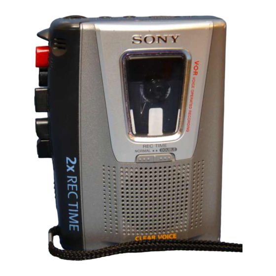
Photo: TCM-20DV
Model Name Using Similar Mechanism
Tape Transport Mechanism Type
SPECIFICATIONS
Supplied accessories
The instructions in this manual are for
4 models.
The TCM-20DV is the model used for
illustration purposes.
TCM-
23DV 22DV 21DV 20DV
AC power adaptor (1)
—
a
—
—
Battery charger adaptor (1)
—
a
—
—
Rechargeable batteries (2)
(NC-AA, 1.2V, 700mAh,
—
a
—
—
Ni-Cd)
Cassette tape C-90 (1)
—
—
a
—
Battery LR6 (2)
—
—
a
—
Monaural microphone (1)
—
—
a
—
Super-directional
a
—
—
—
microphone (1)
Carrying pouch (1)
—
—
a
—
Hand strap (1)
a
a
a
a
(attached to the unit)
Battery life
(Approx. hours) (EIAJ*)
Playback
Recording
Sony alkaline
11
11
LR6 (SG)
Sony R6P (SR)
3
3
Sony
rechargeable
battery
3
3
(NC-AA) fully
charged (TCM-
22DV only)
* Measured value by the standard of
EIAJ (Electronic Industries
Association of Japan). (Using a Sony
HF series cassette tape and playing
back with speakers)
Note
The battery life may shorten
depending on the operation of the
unit.
For maximum performance we
recommend that you use alkaline
batteries.
TCM-20DV/21DV/
22DV/23DV
US Model
TCM-20DV/21DV/22DV/23DV
Canadian Model
TCM-20DV/22DV
AEP Model
TCM-20DV/21DV
TCM-20DV/23DV
Chinese Model
NEW
MT-20DV-118
House Current
(see Fig. A- )
Connect the AC power adaptor to
DC IN 3V and to a wall outlet. The
AC power adaptor is supplied only
with the TCM-22DV. For other
models, use the AC-E30HG AC
power adaptor (not supplied). Do
not use any other AC power
adaptor.
Polarity of
the plug
Note
Specifications for AC-E30HG vary for
each area. Check your local voltage
and the shape of the plug before
purchasing.
Design and specifications are subject
to change without notice.
CASSETTE-CORDER
E Model
TCM-20DV
Advertisement
Table of Contents

Related Manuals for Sony TCM-20DV


Summary of Contents for Sony TCM-20DV
- Page 1 Tape speed 4 models. DC IN 3V and to a wall outlet. The 4.8 cm/s or 2.4 cm/s The TCM-20DV is the model used for AC power adaptor is supplied only Frequency range illustration purposes. with the TCM-22DV. For other...
-
Page 2: Table Of Contents
DE FONCTIONNEMENT. NE REMPLACER CES COM- • Never reuse a disconnected chip component. POSANTS QUE PAR DES PIÈCES SONY DONT LES • Notice that the minus side of a tantalum capacitor may be dam- NUMÉROS SONT DONNÉS DANS CE MANUEL OU aged by heat. -
Page 3: General
SECTION 2 This section is extracted from instruction manual. GENERAL • Location of Controls Built-in mic BATT z REC x STOP B PLAY REC TIME m REW/ REVIEW SPEED CONTROL PAUSE M FF/CUE DC IN 3 V – 3 – Get user manuals: See SafeManuals.com... -
Page 4: Disassembly
SECTION 3 DISASSEMBLY • This set can be disassembled in the order shown below. BELT MAIN BOARD, MECHANISM DECK (MT-20DV-118) CABINET (REAR), CASSETTE LID Note: Follow the disassembly procedure in the numerical order given. CABINET (REAR), CASSETTE LID INSTALLATION CASSETTE SPRING cabinet front 9 cassette lid cassette lid... - Page 5 MAIN BOARD, MECHANISM DECK (MT-20DV-118) 5 three screws (IB lock) 6 claw 7 mechanism deck (MT-20DV-118) 1 Remove the two solders electret condenser microphone (MIC101). 1 Remove the two solders motor (M901). 4 MAIN board 1 Remove the two solders 3 screw magnetic head (HRP901).
- Page 6 INSTALLATION MAIN BOARD On installation MAIN board, adjust to the S101 and the S102. screw (1.7) screw (M1.4) MAIN board S102 (POWER) S101 (REC/PB) lever (REC) – 6 – Get user manuals: See SafeManuals.com...
-
Page 7: Mechanical Adjustments
SECTION 4 MECHANICAL ADJUSTMENTS 1. Clean the following parts with a denatured-alcohol-moistened swab: record/playback head pinch roller erase head rubber belt capstan idlers 2. Demagnetize the record/playback head with a head demagne- tizer. (Do not bring the head demagnetizer close to the erase head.) 3. -
Page 8: Electrical Adjustments
SECTION 5 ELECTRICAL ADJUSTMENTS Tape Speed Adjustment Setting: • Supplied voltage: 2.5 V Mode: playback • Switch and control position test tape [VOL control (RV101) : mechanical center frequency WS-48A [PAUSE switch (S105) : OFF counter (3 kHz, 0 dB) [SPEED CONTROL] (RV602): center click 10 k Ω... -
Page 9: Diagrams
TCM-20DV/21DV/22DV/23DV SECTION 6 DIAGRAMS 6-1. BLOCK DIAGRAM MIC101 • SIGNAL PATH : PLAY : RECORD J101 VREF (PLUG IN POWER) Q101 S101 (2/6) CONTROL MIC AMP, REC/PB EQ AMP Q104 POWER AMP, VOR CONTROL,REGULATOR S101 (3/6) (REC/PB) IC101 (1/3) PB EQ... -
Page 10: Printed Wiring Board
TCM-20DV/21DV/22DV/23DV 6-2. PRINTED WIRING BOARDS J101 J102 (PLUG IN POWER) D101 MIC101 (CONDUCTOR SIDE) MAIN BOARD (COMPONENT SIDE) MAIN BOARD BATT S104 RV101 R118 C144 –2 C146 –1 R125 C133 S101 R115 (REC/PB) C148 R103 R102 R105 –3 –6 C107 R106 –2... -
Page 11: Schematic Diagram
TCM-20DV/21DV/22DV/23DV 6-3. SCHEMATIC DIAGRAM • See page 15 for IC Block Diagram. Note on Schematic Diagram: • All capacitors are in µF unless otherwise noted. pF: µµF • Voltages are dc with respect to ground under no-signal 50 WV or less are not indicated except for electrolytics conditions. -
Page 12: Exploded Views
SECTION 7 EXPLODED VIEWS • IC Block Diagram NOTE: • Items marked “*” are not stocked since they • -XX and -X mean standardized parts, so they IC101 LA4168ML-TE-L may have some difference from the original are seldom required for routine service. Some one. - Page 13 (2) MECHANISM DECK SECTION-1 (MT-20DV-118) HRP901 HE901 M901 supplied Ref. No. Part No. Description Remark Ref. No. Part No. Description Remark X-3377-250-1 LEVER, (2) ASSY, PINCH 3-924-674-01 SPRING (B. T), COMPRESSION 3-925-146-01 BUTTON (FF) (M) 3-924-641-01 GEAR (T REEL) 3-925-147-01 BUTTON (REW) (m) 3-924-726-01 SPRING (M GROUND), TORSION 3-925-148-01 BUTTON (PLAY) (N) 3-907-943-01 BELT (CAPSTAN)
- Page 14 (3) MECHANISM DECK SECTION-2 (MT-20DV-118) supplied Ref. No. Part No. Description Remark Ref. No. Part No. Description Remark 3-321-483-11 RING, RETAINING (0.25) 3-924-633-01 SPRING (STOP), TENSION 3-315-495-31 WASHER 3-924-622-01 LEVER (STOP) X-3370-384-1 FLYWHEEL ASSY 3-924-643-01 SPRING (PR), TORSION 3-924-623-01 LEVER (PLAY) 3-924-684-01 SPRING (LOCK PLATE), TENSION 3-924-621-01 LEVER (REW) 3-924-619-01 LEVER (SW)
-
Page 15: Electrical Parts List
SECTION 8 MAIN ELECTRICAL PARTS LIST NOTE: • Due to standardization, replacements in the • Items marked “*” are not stocked since they The components identified by mark 0 or dotted line with mark parts list may be different from the parts speci- are seldom required for routine service. - Page 16 TCM-20DV/21DV/22DV/23DV MAIN Ref. No. Part No. Description Remark Ref. No. Part No. Description Remark R105 1-216-049-11 RES-CHIP 1/10W < THERMISTOR > R106 1-216-049-11 RES-CHIP 1/10W THP601 1-810-007-11 THERMISTOR, POSITIVE R108 1-216-085-00 METAL CHIP 1/10W THP602 1-809-350-21 THERMISTOR, NTC (2125) R109...
Need help?
Do you have a question about the TCM-20DV and is the answer not in the manual?
Questions and answers