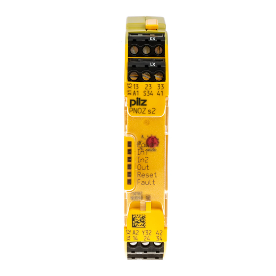
Pilz PNOZ s2 Operating Manual
Safety relays
Hide thumbs
Also See for PNOZ s2:
- Operating instructions manual (8 pages) ,
- Operating instructions manual (16 pages)
Table of Contents
Advertisement
Advertisement
Table of Contents

Related Manuals for Pilz PNOZ s2


Summary of Contents for Pilz PNOZ s2
- Page 1 PNOZ s2 Safety relays Operating Manual-21394-EN-11...
- Page 2 Preface This document is the original document. All rights to this documentation are reserved by Pilz GmbH & Co. KG. Copies may be made for the user's internal purposes. Suggestions and comments for improving this documenta- tion will be gratefully received.
-
Page 3: Table Of Contents
..........................Status indicators ........................Error indicators ......................... Faults - malfunctions ......................Dimensions in mm ......................... Technical Details ........................Safety characteristic data ......................Classification according to ZVEI, CB24I ................... Supplementary data ......................Service life graph ........................Operating Manual PNOZ s2 21394-EN-11... - Page 4 Contents Permitted operating height......................Remove plug-in terminals ..................... Order reference ........................EC declaration of conformity ....................Operating Manual PNOZ s2 21394-EN-11...
-
Page 5: Introduction
PNOZ s2 Introduction Validity of documentation This documentation is valid for the product PNOZ s2. It is valid until new documentation is published. This operating manual explains the function and operation, describes the installation and provides guidelines on how to connect the product. -
Page 6: Safety
EN ISO 13849 and EN 62061. However, this does not guarantee the functional safety of the overall plant/machine. To achieve the relevant safety level of the overall plant/ machine’s required safety functions, each safety function needs to be considered separ- ately. Operating Manual PNOZ s2 21394-EN-11... -
Page 7: Use Of Qualified Personnel
Note for overvoltage category III: If voltages higher than low voltage (>50 VAC or >120 VDC) are present on the unit, connected control elements and sensors must have a rated insulation voltage of at least 250 V. Operating Manual PNOZ s2 21394-EN-11... -
Page 8: Unit Features
The circuit is internally redundant with built-in self-monitoring. The safety device remains effective in the case of a component failure. The correct opening and closing of the safety device relays is tested automatically in each on-off cycle. Operating Manual PNOZ s2 21394-EN-11... -
Page 9: Block Diagram/Terminal Configuration
(see technical details). Increase in the number of available instantaneous safety contacts by connecting contact expander modules or external contactors/relays; A connector can be used to connect 1 PNOZsigma contact expansion module. Operating Manual PNOZ s2 21394-EN-11... -
Page 10: Timing Diagram
Remove the plug terminator at the side of the base unit and at the contact expansion module. Connect the base unit and the contact expansion module to the supplied connector be- fore mounting the units to the DIN rail. Operating Manual PNOZ s2 | 10 21394-EN-11... -
Page 11: Wiring
Adequate protection must be provided on all output contacts with capacitive and inductive loads. The power supply must comply with the regulations for extra low voltages with protective electrical separation (SELV, PELV) in accordance with VDE 0100, Part 410. Operating Manual PNOZ s2 | 11 21394-EN-11... -
Page 12: Preparing For Operation
If the operating mode selector switch "mode" is in its start position (vertical position), an error message will appear. Operating mode se- Automatic/manual Monitored start rising Monitored start fall- lector switch "mode" start edge ing edge without detection of shorts across con- tacts Operating Manual PNOZ s2 | 12 21394-EN-11... -
Page 13: Connection
(see Safety characteristic data [ 23]). Start circuit/feedback loop Without feedback loop monit- with feedback loop monitoring oring Automatic start 13 (23,33) 14 (24,34) Monitored, manual start/restart 13 (23,33) 14 (24,34) Operating Manual PNOZ s2 | 13 21394-EN-11... - Page 14 *Connect together the 0V connections on all the external power supplies INFORMATION If a base unit and a contact expansion module from the PNOZsigma range are connected via the connector, no additional wiring is necessary. Operating Manual PNOZ s2 | 14 21394-EN-11...
-
Page 15: Application Example
SIL CL 2/PL d at least 1x per year NOTICE The safety function should be checked after initial commissioning and each time the plant/machine is changed. The safety functions may only be checked by qualified personnel. Operating Manual PNOZ s2 | 15 21394-EN-11... -
Page 16: Status Indicators
Diagnostics: Internal error, unit defective Remedy: Switch supply voltage off and then on again, change unit if neces- sary. POWER Diagnostics: Supply voltage too low Remedy: Check supply voltage and increase if necessary. RESET FAULT Operating Manual PNOZ s2 | 16 21394-EN-11... -
Page 17: Faults - Malfunctions
Faults - malfunctions Contact malfunctions: If the contacts have welded, reactivation will not be possible after the input circuit has opened. Dimensions in mm *with spring-loaded terminals 98 (3.86") 17,5 (0.69") * 100 (3,94") Operating Manual PNOZ s2 | 17 21394-EN-11... -
Page 18: Technical Details
0,1 mA 0,1 mA Max. internal voltage drop Conditional rated short circuit cur- rent 100 A 100 A Lowest operating current 0 mA 0 mA Utilisation category in accordance with EN 60947-1 DC-12 DC-12 Operating Manual PNOZ s2 | 18 21394-EN-11... - Page 19 DC13 (6 cycles/min) at 24 V 24 V Max. current Utilisation category of auxiliary con- tacts AC15 at 230 V 230 V Max. current DC13 (6 cycles/min) at 24 V 24 V Max. current Operating Manual PNOZ s2 | 19 21394-EN-11...
- Page 20 751102 while loading several contacts Ith per contact at UB DC; AC1: 240 V, DC1: 24 V Conv. therm. current with 1 con- tact Conv. therm. current with 2 con- tacts Conv. therm. current with 3 con- tacts Operating Manual PNOZ s2 | 20 21394-EN-11...
- Page 21 93 % r. h. at 40 °C 93 % r. h. at 40 °C Condensation during operation Not permitted Not permitted EN 60947-5-1, EN 61000-6-2, EN EN 60947-5-1, EN 61000-6-2, EN 61000-6-4, EN 61326-3-1 61000-6-4, EN 61326-3-1 Operating Manual PNOZ s2 | 21 21394-EN-11...
- Page 22 Conductor cross section with spring-loaded terminals: Flexible with/without crimp connector – 0,2 - 2,5 mm², 24 - 12 AWG Spring-loaded terminals: Terminal points per connection – Stripping length with spring-loaded terminals – 9 mm Operating Manual PNOZ s2 | 22 21394-EN-11...
-
Page 23: Safety Characteristic Data
A safety function's SIL/PL values are not identical to the SIL/PL values of the units that are used and may be different. We recommend that you use the PAScal software tool to calculate the safety function's SIL/PL values. Operating Manual PNOZ s2 | 23 21394-EN-11... -
Page 24: Classification According To Zvei, Cb24I
Relay outputs Interfaces Source Interface Module Class Drain Interface Actuator Class Source parameters Min. switching voltage 12 V Max. switching voltage 250 V Min. switching current 0,003 A Max. switching current Potential isolation Operating Manual PNOZ s2 | 24 21394-EN-11... -
Page 25: Supplementary Data
The service life graphs indicate the number of cycles from which failures due to wear must be expected. The wear is mainly caused by the electrical load; the mechanical load is negli- gible. Switching current (A) Fig.: Service life graphs at 24 V DC and 230 V AC Operating Manual PNOZ s2 | 25 21394-EN-11... - Page 26 To increase the service life, sufficient spark suppression must be provided on all output contacts. With capacitive loads, any power surges that occur must be noted. With DC con- tactors, use flywheel diodes for spark suppression. Operating Manual PNOZ s2 | 26 21394-EN-11...
- Page 27 From an operating height of 2000 m the max. permitted ambient temperature is reduced by 0.5 °C/100 m Operating height Permitted ambient temperature 3000 m 50 °C 4000 m 45 °C 5000 m 40 °C Operating Manual PNOZ s2 | 27 21394-EN-11...
- Page 28 European Parliament and of the Council. The complete EC Declaration of Conformity is available on the Internet at www.pilz.com/downloads. Authorised representative: Norbert Fröhlich, Pilz GmbH & Co. KG, Felix-Wankel-Str. 2, 73760 Ostfildern, Germany Operating Manual PNOZ s2...
- Page 29 We are represented internationally. Please refer to our homepage www.pilz.com for further details or contact our headquarters. Headquarters: Pilz GmbH & Co. KG, Felix-Wankel-Straße 2, 73760 Ostfildern, Germany Telephone: +49 711 3409-0, Telefax: +49 711 3409-133, E-Mail: info@pilz.com, Internet: www.pilz.com...
Need help?
Do you have a question about the PNOZ s2 and is the answer not in the manual?
Questions and answers