Table of Contents
Advertisement
Advertisement
Table of Contents

Related Manuals for Pilz PNOZ s7.2


Summary of Contents for Pilz PNOZ s7.2
- Page 1 PNOZ s7.2 Safety relays Operating Manual-21866-EN-10...
- Page 2 Preface This document is the original document. All rights to this documentation are reserved by Pilz GmbH & Co. KG. Copies may be made for the user's internal purposes. Suggestions and comments for improving this documenta- tion will be gratefully received.
-
Page 3: Table Of Contents
Wiring Preparing for operation Operation Status indicators Faults - malfunctions Dimensions in mm Technical details Safety characteristic data Supplementary data Service life graph Permitted operating height Remove plug-in terminals Order reference EC declaration of conformity Operating Manual PNOZ s7.2 21866-EN-10... -
Page 4: Introduction
PNOZ s7.2 Introduction Validity of documentation This documentation is valid for the product PNOZ s7.2. It is valid until new documentation is published. This operating manual explains the function and operation, describes the installation and provides guidelines on how to connect the product. -
Page 5: Safety
In order to achieve the re- quired safety level for the overall plant/machine, define the safety requirements for the plant/machine and then define how these must be implemented from a technical and organ- isational standpoint. Operating Manual PNOZ s7.2 21866-EN-10... -
Page 6: Use Of Qualified Personnel
Note for overvoltage category III: If voltages higher than low voltage (>50 VAC or >120 VDC) are present on the unit, connected control elements and sensors must have a rated insulation voltage of at least 250 V. Operating Manual PNOZ s7.2 21866-EN-10... -
Page 7: Unit Features
The safety function remains effective in the case of a component failure. Earth fault in the feedback loop: Detected, depending on the base unit that is used. Earth fault in the input circuit: The output relays de-energise and the safety contacts open. Operating Manual PNOZ s7.2 21866-EN-10... -
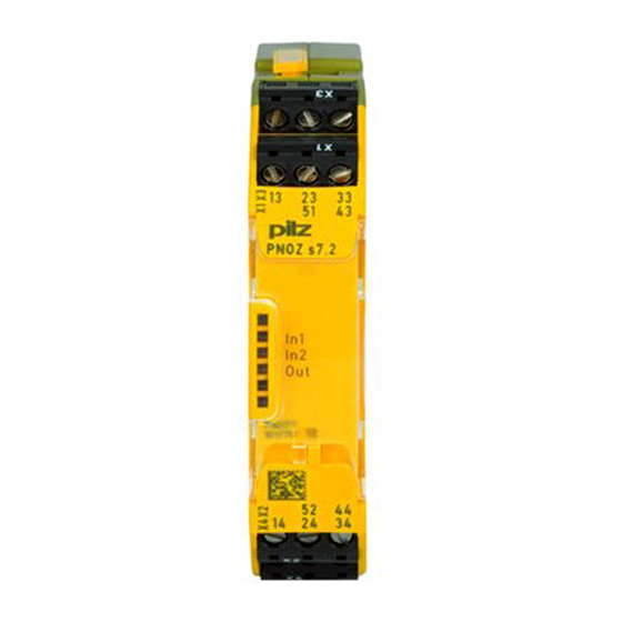
Page 8: Block Diagram/Terminal Configuration
Dual-channel operation and supply voltage via PNOZsigma connector with PNOZsigma expander modules: Dual-channel operation and supply voltage via PNOZsigma connector Installation Connect contact expansion module PNOZ s7.2 to PNOZsigma contact expansion modules Connect the contact expansion modules using the connector supplied. Control cabinet installation The safety relay should be installed in a control cabinet with a protection type of at least IP54. - Page 9 : Contact expansion module PNOZ s7.2 : Expansion module PNOZ s7, s8, s9, s10, s11 as a terminator : Contact expansion module PNOZ s7.1 with ter- minator : Contact expansion module PNOZ s7.2 : Contact expansion module PNOZ s7.2 with ter- minator Operating Manual PNOZ s7.2 21866-EN-10...
-
Page 10: Wiring
To prevent contact welding, a fuse should be connected before the output contacts (see Technical details [ 12]). Use copper wire that can withstand 60/75 °C. Sufficient fuse protection must be provided on all output contacts with capacitive and in- ductive loads. Operating Manual PNOZ s7.2 21866-EN-10... -
Page 11: Preparing For Operation
The safety functions may only be checked by qualified personnel. LEDs indicate the status and errors during operation: LED on Status indicators Channel 1 actuated. Channel 2 actuated. IN1, IN2, OUT Safety contacts are closed. Operating Manual PNOZ s7.2 21866-EN-10... -
Page 12: Faults - Malfunctions
Relay outputs 750177 751177 Number of output contacts Safety contacts (N/O), instant- aneous Auxiliary contacts (N/C) 1 kA 1 kA Max. short circuit current IK Utilisation category In accordance with the standard EN 60947-4-1 EN 60947-4-1 Operating Manual PNOZ s7.2 21866-EN-10... - Page 13 Max. current Utilisation category in accordance with UL Voltage 240 V AC G.U. (same polarity) 240 V AC G.U. (same polarity) With current 24 V DC G. U. 24 V DC G. U. Voltage With current Operating Manual PNOZ s7.2 21866-EN-10...
- Page 14 With power failure max. Environmental data 750177 751177 Climatic suitability EN 60068-2-78 EN 60068-2-78 Ambient temperature -10 - 55 °C -10 - 55 °C Temperature range Storage temperature Temperature range -40 - 85 °C -40 - 85 °C Operating Manual PNOZ s7.2 21866-EN-10...
- Page 15 – Conductor cross section with spring-loaded terminals: Flexible with/without crimp connector – 0,2 - 2,5 mm², 24 - 12 AWG Spring-loaded terminals: Terminal points per connection – Stripping length with spring-loaded terminals – 9 mm Operating Manual PNOZ s7.2 21866-EN-10...
-
Page 16: Safety Characteristic Data
A safety function's SIL/PL values are not identical to the SIL/PL values of the units that are used and may be different. We recommend that you use the PAScal software tool to calculate the safety function's SIL/PL values. Operating Manual PNOZ s7.2 21866-EN-10... -
Page 17: Supplementary Data
The service life graphs indicate the number of cycles from which failures due to wear must be expected. The wear is mainly caused by the electrical load; the mechanical load is negli- gible. Switching current (A) Fig.: Service life graphs at 24 V DC and 230 V AC Operating Manual PNOZ s7.2 21866-EN-10... - Page 18 To increase the service life, sufficient spark suppression must be provided on all output contacts. With capacitive loads, any power surges that occur must be noted. With DC con- tactors, use flywheel diodes for spark suppression. Operating Manual PNOZ s7.2 21866-EN-10...
-
Page 19: Permitted Operating Height
From an operating height of 2000 m the max. permitted ambient temperature is re- duced by 0.5 °C/100 m Operating height Permitted ambient temperature 3000 m 50 °C 4000 m 45 °C 5000 m 40 °C Operating Manual PNOZ s7.2 21866-EN-10... -
Page 20: Remove Plug-In Terminals
European Parliament and of the Council. The complete EC Declaration of Conformity is available on the Internet at www.pilz.com/downloads. Representative: Norbert Fröhlich, Pilz GmbH & Co. KG, Felix-Wankel-Str. 2, 73760 Ost- fildern, Germany Operating Manual PNOZ s7.2... - Page 21 Back cover Support Technical support is available from Pilz round the clock. Americas Australia Scandinavia +45 74436332 Brazil +61 3 95600621 +55 11 97569-2804 Spain Canada Europe +34 938497433 +1 888-315-PILZ (315-7459) Austria Switzerland Mexico +43 1 7986263-0 +41 62 88979-30...
Need help?
Do you have a question about the PNOZ s7.2 and is the answer not in the manual?
Questions and answers