Table of Contents
Advertisement
Quick Links
Service Manual
SDA601
Serial Digital Analyzer
070-8914-04
Warning
The servicing instructions are for use by qualified
personnel only. To avoid personal injury, do not
perform any servicing unless you are qualified to
do so. Refer to all safety summaries prior to
performing service.
www.tektronix.com
Advertisement
Table of Contents

Related Manuals for Tektronix SDA601


Summary of Contents for Tektronix SDA601
- Page 1 Service Manual SDA601 Serial Digital Analyzer 070-8914-04 Warning The servicing instructions are for use by qualified personnel only. To avoid personal injury, do not perform any servicing unless you are qualified to do so. Refer to all safety summaries prior to performing service.
- Page 2 Copyright © Tektronix, Inc. All rights reserved. Licensed software products are owned by Tektronix or its subsidiaries or suppliers, and are protected by national copyright laws and international treaty provisions. Tektronix products are covered by U.S. and foreign patents, issued and pending. Information in this publication supercedes that in all previously published material.
- Page 3 Tektronix, with shipping charges prepaid. Tektronix shall pay for the return of the product to Customer if the shipment is to a location within the country in which the Tektronix service center is located.
-
Page 5: Table Of Contents
2- -1 Connecting the SDA601 ......... . . - Page 6 Table of Contents Adjust SLM (Signal Level Meter) ....... . 4- -2 Adjust the Deserializer VCO (“Serial Pot”) .
- Page 7 ..... 2- -9 Figure 2- -7: The Initial SDA601 Utility Menu Display ... .
- Page 8 ......5- -7 Figure 5- -3: Exploded View of the SDA601 .....
- Page 9 Table of Contents List of Tables Table 1- -1: Serial Digital Video Input ......1- -2 Table 1- -2: Signal Level Meter .
-
Page 11: General Safety Summary
General Safety Summary Review the following safety precautions to avoid injury and prevent damage to this product or any products connected to it. To avoid potential hazards, use this product only as specified. Only qualified personnel should perform service procedures. To Avoid Fire or Use Proper Power Cord. - Page 12 General Safety Summary Do Not Operate in an Explosive Atmosphere. Keep Product Surfaces Clean and Dry. Terms in this Manual These terms may appear in this manual: WARNING. Warning statements identify conditions or practices that could result in injury or loss of life. CAUTION.
-
Page 13: Service Safety Summary
Service Safety Summary Only qualified personnel should perform service procedures. Read this Service Safety Summary and the General Safety Summary before performing any service procedures. Do Not Service Alone. Do not perform internal service or adjustments of this product unless another person capable of rendering first aid and resuscitation is present. - Page 14 Directive 2002/96/EC on waste electrical and electronic equipment (WEEE). For information about recycling options, check the Support/Service section of the Tektronix Web site (www.tektronix.com). Battery Recycling. This product may contain a Nickel Cadmium (NiCd) rechargeable battery, which must be recycled or disposed of properly. Please properly dispose of or recycle the battery according to local government regulations.
-
Page 15: Specifications
Specifications... -
Page 17: Introduction
Specifications Introduction The material in this section is organized into two main groupings: the specifica- tion tables and the supporting figures. The specification tables include: H General input and output signal characteristics and specifications H Physical and environmental specifications The supporting figures (waveform diagrams and related data) follow the specification tables. -
Page 18: Specification Tables
Specifications Specification Tables Table 1- - 1: Serial Digital Video Input Characteristic Performance Requirements Supplemental Information Format CCIR 601 Component 525/625, 10 bits data, Scrambled NRZI; 270 Mb/s. Complies with SMPTE 259M and CCIR 656. 75 Ω Input Impedance 800 mV ± 80 mV (peak-to-peak) at signal source Input Level ≥... -
Page 19: Table 1- -5: Physical Characteristics
Specifications Table 1- - 4: Power Supply (Cont.) Characteristic Performance Requirements Supplemental Information Power Limit without adapter with adapter Power Consumption Typical: Back light off 5.0 W Back light on 5.5 W Table 1- - 5: Physical Characteristics Characteristic Information Height 5.6 cm (2.2 in) Width... -
Page 20: Certifications And Compliances
Specifications Certifications and Compliances EC Declaration of Meets intent of Directive 89/336/EEC for Electromagnetic Compatibility. Conformity - - EMC Compliance was demonstrated to the following specifications as listed in the Official Journal of the European Communities: EN 55103. Product family standard for audio, video, audio-visual and entertain- ment lighting control apparatus for professional use. -
Page 21: Operating Information
Operating Information... -
Page 23: Getting Started
Supplying Power The SDA601 is DC powered. You may power it with the standard AC adapter, the optional 9.6 V NiCad battery pack, eight standard AA batteries, or a “BP” type external battery pack with the correct voltage and polarity. The external DC power connector is on the left side of the instrument. -
Page 24: Figure 2- 1: Opening The Battery Compartment
To install AA batteries or the battery pack, open the battery compartment of the SDA601 by pressing down on the cover and sliding it in the direction of the inscribed arrow, as shown in Figure 2- -1. When the cover tabs line up with the slots in the case, lift the cover away from the instrument. -
Page 25: Connecting The Sda601
(This may be disabled through the Utility/Diagnostics/ Power Manage menu; see page 2- -12.) H To guard against battery discharge if you forget to turn the SDA601 off, enable Auto Power Off through the Utility/Diagnostics/Power Manage menu (see page 2- -11). -
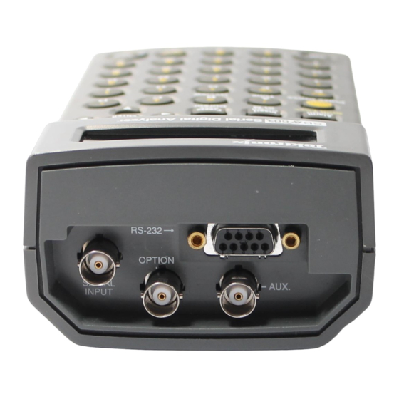
Page 26: Serial Input
PROCOMMR or the Terminal accessory of MicrosoftR WindowsT. With a printer or PC connected, you can choose—through the Alarm menu—to have the SDA601 log every error as it occurs, or to print a Watch report every ten seconds. This will permit unattended monitoring of your system. -
Page 27: Figure 2- 3: Connecting To A Dte Device With A Db25 Serial Port
NOTE. RS-232 signals are named from the perspective of the DTE device. Since the SDA601 is a DCE device, pin 2 (“Received Data”) is an output from the instrument; that is, the data is received by the connected DTE device. - Page 28 RS-232 connector. If you have trouble outputting from the SDA601, first verify that communication parameter and Baud rate settings are correct, then try reversing the conductors at pins 2 and 3 and 7and 8 at the cable end that is connected to the SDA.
-
Page 29: Figure 2- 5: A Printed Analysis Report
Operating Information Figure 2- 5: A Printed Analysis Report 2- 7 SDA 601 Serial Digital Analyzer... -
Page 30: Keypad And Display Conventions
Keypad and Display Conventions Please see the Instruction card (Tektronix part number 070-8912-00) supplied with your SDA601 for a “tour” of the keypad and an explanation of the display symbols. For your convenience, the following panels are taken from the card. -
Page 31: The On-Screen Display (Osd)
Analysis or Watch session on the SDA601 LCD. See page 2- -23. The On-Screen Display (OSD) The OSD is a 12 line, 24 column display that can contain results from SDA601 Analyze and Watch sessions. It can be superimposed on the AUX output and Insert viewed on an attached video monitor. -
Page 32: Preliminary Settings
Operating Information H Similar reversed “S” and “SL” icons (not shown) will appear when SDA601 keypad is shifted and shift locked. H The down-arrow in the lower right indicates that the key may be used to reveal another (higher-numbered) page. An up-arrow will appear in all other pages to indicate that the key may be used. -
Page 33: Set The Battery Type
“Auto Power Off” will switch the instrument off when ten minutes have passed Power Off without a key press. Enable this feature when you are using battery power and operating in an environment in which unplanned shutdown of the SDA601 is permissible. 1. While still in the Utility/Diagnostics/Power Manage submenu, press the key twice to scroll to the Auto Power Off item. -
Page 34: Disable (Enable) Timed Lcd Backlight Turn Off
Disable (Enable) Timed Another power saving feature of the SDA601 is timed turn-off of the LCD LCD Backlight Turn Off backlight. It is enabled by default in a new or reset instrument. If you will always operate with the AC adapter, you may wish to disable the feature. -
Page 35: Analyzing A Signal
Operating Information H View decoded video on an analog picture monitor attached to the AUX output (see page 2- -4) H Highlight, on the picture monitor, selected signal conditions or errors in the context of the video signal. (page 2- -24) H Measure the approximate level of the digital input signal with the built-in Signal Level Meter (SLM;... -
Page 36: Figure 2- 10: The Analyze Osd
Operating Information video monitor) as well as on the SDA601 LCD. The SDA601 up and down arrow keys are used to scroll through the list of detected “conditions.” The conditions detected and reported in an SDA601 analysis are: Video format... -
Page 37: Watching A Signal
Other stuck bits may suggest either an incorrect signal or faulty equipment. Zero-length ANC. Is reported by the SDA601 when a Ø-value ANC “Data Count word” is detected in the input data. The detection of zero-length ANC is... -
Page 38: Figure 2- 11: The Initial Sda601 Utility Menu Display
Zero length ANC (yes/no) EDH flag set/not set When only the Data Value group is set to “Watch,” then, the SDA601 will actually observe the status of ten conditions—the eight default conditions, plus Illegal Values and Video In/Out of Range. If all four groups are selected, all 20 conditions will be monitored. -
Page 39: Figure 2- 12: The Sda601 "Watching" Display
Insert On/Off , if necessary. Figure 2- 12: The SDA601 “Watching” Display 4. Review the condition list on the SDA601 LCD by pressing the key until you reach the END OF LIST message. Use to scroll back up the list as desired. -
Page 40: Figure 2- 13: Watch Errors Reported On The Osd
Watch menu. After the analysis, or on leaving the Watch Watch menu, you may begin a new Watch session by pressing . Note that the SDA601 will “forget” all data collected during a Watch session when the session is concluded. Watch Restarting a Watch session. Pressing... -
Page 41: Alarms
H Log each error — or as many as the printer buffer allows. Intended for extended monitoring of the signal when few, if any errors are expected. You can leave the SDA601 (powered by the AC adapter) and a printer unattended to log and help diagnose intermittent problems. This is the... -
Page 42: Lcd Display Modes
On through the “Alarm On/Off” menu item or with the On/Off key. LCD Display Modes Three SDA601 LCD display modes—SLM (Signal Level Meter), Cursor, and Time—may be invoked directly with the corresponding key (see Figure 2- -14), or Display Select through the key/menu. -
Page 43: Figure 2- 14: The Display Mode Selection Keys
Review four display modes are explained in the next few paragraphs. Figure 2- 14: The Display Mode Selection Keys SLM Display Mode. The SDA601 displays the relative level of the serial digital SLM (A) input signal when you press the key, or toggle “Disp Sig Level”... -
Page 44: Figure 2- 16: The Cursor Data Display
Operating Information that follow. See Figure 2- -16. The location of the selected word in the video frame is also indicated by “cross hair” cursors in the AUX output; connect an analog video monitor to see the cross hairs. Figure 2- 16: The Cursor Data Display The first line of the cursor data display contains the hexadecimal values of the selected word and the three that follow it. -
Page 45: Aux Output Modes
Review sion—or the most recent Analysis—on the LCD. Once you have pressed , the SDA601 display will resemble one of the two shown in Figure 2- -18; use key to review the status of individual Analyze or Watch items. Figure 2- 18: The First Review Display AUX Output Modes Recall that the AUX output signal is “pseudo-video”... - Page 46 Highlighting. See page 2- -9 for an explanation of the OSD; Pulse Cross and Highlighting are discussed in the following paragraphs. Pulse Cross. Pulse Cross is an SDA601 AUX output mode that allows the user to “see” the horizontal and/or vertical intervals, which are normally blanked in video monitors.
-
Page 47: Saving And Recalling Presets
Note that the ANC highlight conditions occur in the horizontal or vertical interval. Use Pulse Cross to “see” those conditions. Saving and Recalling The configuration of the SDA601 at any given time may be saved as a Preset for Presets later recall. Three different instrument configurations can be saved. Using... -
Page 48: Software Reset
NOTE. Recalling a preset will turn Watch mode off. Software Reset To reset the instrument NVRAM and restore the SDA601 to “factory” default settings, select the Factory Reset item in the Utility/Diagnostics/NVRAM/TIC Dgs submenu. See page 3- -6 for instructions. -
Page 49: Performance Verification
Performance Verification... -
Page 51: Required Test Equipment
Table 3- 1: Required Test Equipment Item Information/Requirements Example AC Adapter Std. SDA601 accessory Cable Simulator Able to simulate 25 and 150 Faraday Cable Clone meters of Belden 8281 coax- ial cable. Video Measurement Set... - Page 52 60% Sweep; Erroneous FF CRC Erroneous AP CRC Zero-value (Ø) AP CRC Spectrum Analyzer Freq. Range: 325 MHz Tektronix 2712 Option 04 Sensitivity: up to 50 dB Internal tracking generator N-to-BNC adapter Male N to female BNC Standard Tektronix 2712 accessory;...
- Page 53 Performance Verification Procedures Performance Verification Checklist Use the following checklist if you are familiar with the operation of the SDA601 as well as digital video performance verification techniques. Step-by-step instructions for all of the procedures begin on page 3- -4.
-
Page 54: Preparation
Performance Verification Procedures Performance Verification Procedures Use the following step-by-step procedures to verify that the SDA601 meets published specifications (see Section 1 of this manual). The order of these procedures has been chosen to minimize changes in equipment setup. Perfor- mance parameters may be checked in any order. -
Page 55: Table 3- 2: Initial Settings For The Video Measurement Set
Performance Verification Procedures 2. Switch the equipment on and allow a 20-minute warm-up. Set the front panel controls of the Tektronix 1780 (or 1781) as listed in Table 3- -2. Table 3- 2: Initial Settings for the Video Measurement Set... -
Page 56: Procedures
Performance Verification Procedures Figure 3- 3: The Initial SDA601 Utility Menu Display 4. Reset the SDA601 software through the Utility:Diagnostics:NVRAM/TIC Dgs:Factory Reset menu item. To do so: H Press once to reach the “Diagnostics..” menu item, then press Enter “drop into” the Diagnostics submenu. -
Page 57: Figure 3- 4: The Tsg601 Display Indicating Normal Crcs
Continuing from the previous procedure, press the button, then press to access the “Keypad Test” menu item. ENTER b. Press every SDA601 key and button (except ) one at a ENTER time. Verify that the name of each key/button is written to the second LCD line when the key or button is pressed. -
Page 58: Figure 3- 5: The Analyze Osd
Performance Verification Procedures Figure 3- 5: The Analyze OSD Press on the SDA601 to view the second page of the analysis report. Verify that this page contains the following lines: No Illegal Value Video in Range Line/Fld Len OK TRS OK... - Page 59 Performance Verification Procedures Figure 3- 6: The TSG601 Display Indicating an Erroneous FFCRC b. Press the SDA601 Analyze button. The instrument will analyze the incoming signal and, in a few seconds, return to the first page of the analysis report.
-
Page 60: Figure 3- 8: The Tsg601 Display Indicating A Zero Apcrc
Enter Figure 3- 8: The TSG601 Display Indicating a Zero APCRC b. Press the SDA601 Analyze button. The instrument will analyze the incoming signal and, in a few seconds, return the OSD to the first page of the analysis report. -
Page 61: Figure 3- 9: The Sda601 Cursor Display
Performance Verification Procedures Figure 3- 9: The SDA601 Cursor Display c. Move the Cursor vertically to the indicated line. H For 525 line signals, press the SDA601 key once. Verify that the second line of the LCD reads “F2 W 175 L262”... -
Page 62: Figure 3- 10: The First Watch Menu Display
Press Watch e. If the OSD is present on the left display of the video measurement set, press (on the SDA601) to toggle the OSD off. Insert On/Off Enter the SDA601 I/O menu (press , then ). The LCD... - Page 63 Enter b. Press any rectangular SDA601 key to exit the I/O menu. c. On the TSG601, press to select the “60% Sweep” signal. Confirm that the sweep signal is visible on the left “PIX” display of the video measurement set.
- Page 64 SDA601 output is between 225 mV and 375 mV. e. Use the measurement set voltage cursors to verify that the peak Y amplitude of the SDA601 output is between 525 and 875 mV (700 ± 175 mV) above blanking level.
-
Page 65: Figure 3- 12: Page Five Of The Watching Osd
Performance Verification Procedures c. Through the SDA601 Watch menu, set the EDH group to “Watch” and all other groups to “Off.” H Press , then to enter the Watch menu. Shift Watch H Use the keys to select the watch groups. -
Page 66: Figure 3- 13: Sda601-To-Pc Cable Connections
RS-232 Port. 17. Print Report a. Connect a cable wired as shown in Figure 3- -13 between the SDA601 RS-232 connector and the DB25 COM2 port of a personal computer. b. At the PC, run the Terminal accessory of MicrosoftR WindowsT, or another communications application. -
Page 67: Figure 3- 14: Initial Return Loss Setup
Performance Verification Procedures e. Set the following parameters in the SDA601 Utility:RS232 Setup submenu: H Baud Rate = 9600 H Set Parity = None Press , then on the SDA601. Verify that the PC receives a Shift Analyze Analysis report similar to the one shown in Figure 2- -5. - Page 68 Bridge and the SDA, and increases the accuracy of this measurement. m. Confirm that the SDA601 is switched on, then Verify that the spectrum analyzer reference level readout is ≥ 15 dBm (that is, at least 15 dBm down), and that the spectrum analyzer trace is below the reference level at every frequency below the marker frequency.
-
Page 69: Adjustment Procedures
Adjustment Procedures... -
Page 71: Required Test Equipment
Use of inadequate equipment may result in faulty measurements or calibration. Table 4- 1: Required Test Equipment Item Information/Requirements Example AC adapter Std. SDA601 accessory Serial Digital Television Generates (CCIR rec 601) Tektronix Signal Generator Equalizer SDI Checkfield TSG 601 or TSG 422... -
Page 72: Adjust Slm (Signal Level Meter)
Adjustment Procedures Adjustment Procedures Adjust SLM (Signal Level To ensure greatest accuracy of the SDA601 Signal Level meter over the entire Meter) range of operating temperatures, perform this two-part procedure once every twelve months. Please read completely through the following procedure before attempting to adjust the SLM. -
Page 73: Figure 4- 2: The First Slm Calibration Display
ENTER button. c. The SDA601 LCD will be blank for a few seconds. Wait until the message “Set to 100 meter” appears on the top line of the LCD. Set the cable simulator to 100 meters (if using an attenuator, set it to 10 dB), then press the SDA601 button. - Page 74 Wait until the “Calibrate SLM; Saving” message disappears from the SDA601 display to ensure acceptance of the new Cal Factors. 5. Place the SDA601 in an elevated temperature (50_ C = 122_ F) environ- ment for at least one hour. Power the instrument with an AC adapter and leave it switched On, but do not provide an input signal.
- Page 75 Adjustment Procedures Figure 4- 3: A Setup for Adjusting the De-serializer VCO 5. Select the SDA601 Utility/Diagnostics/Calibration/Adj Serial Pot menu item with the following steps: H Hold the Lock Out key down, and press the button. H Press the key once, then press...
- Page 76 313.2 11. Round your result (not the example!) from the previous step to the nearest integer, and enter the value with the SDA601 numeric keys; press ENTER twice to confirm the new setting. When this step is complete, the display should again resemble Figure 4- -4, with the asterisk (*) at the end of the second line.
-
Page 77: Set The Date And Time
During normal instrument operation, press the key. If the date or time Time (F) displayed on the LCD is incorrect, follow these steps to reset the internal clock. 1. Enter the SDA601 Utility menu by holding down, while pressing Lock Out key. - Page 78 Adjustment Procedures 4- 8 SDA 601 Serial Digital Analyzer...
-
Page 79: Maintenance
Maintenance... -
Page 81: Battery Hints
“battery low” message, and also controls the cut-off voltage for instrument operation. Be sure this setting matches the type of battery installed in the SDA601. (See page 2- -11) The Auto Power Down function, when enabled, switches the SDA601 Off to conserve battery life after approximately 10 minutes with no keypress. -
Page 82: Static-Sensitive Components
Maintenance CAUTION. The SDA601 case is made of molded plastic. Do not allow water to get inside of any enclosed assembly or component. Do not clean any plastic materials with organic cleaning solvents, such as benzene, tuolene, xylene, acetone, or similar compounds, because they may damage the plastic. -
Page 83: Troubleshooting Aids
The circuit board assemblies are assigned assembly numbers starting with A1. Circuit boards have been assigned an assembly number so that they may be ordered from Tektronix, Inc. The assembly numbers are as follows: A1 Main Board Assembly A2 Keypad Board Assembly... -
Page 84: Self-Diagnostics
Diagnostics choices, which are listed below. Some of the Diagnostic submenu items are explained in other parts of this manual, or in the SDA601 User manual; the remaining submenu items are discussed after this listing. Show SW/FW Vers Press Enter Power Manage .. - Page 85 Maintenance RS232 loop back Press Enter Disp RS232 outs Off <> On Disp SLM Numeri Off <> On Previous Menu Press Enter NVRAM/TIC Dgs.. Press Enter Get TIC Serial Press Enter Get TIC Time Press Enter Read TIC Memory <> 0 Factory Reset Press Enter Previous Menu...
- Page 86 Fill OSD Screen see page 3- -6 e. Keypad Test see page 3- -7 RS232 loop back — This is a test of the SDA601 RS-232 hardware. To perform this test, short conductors two and three (pins 2 and 3) of the RS-232 connector, then press .
- Page 87 SLM (A) 4. NVRAM/TIC Dgs. The NVRAM/Timer (Touch MemoryT) microprocessor in the SDA601 is contained in a button-shaped stainless steel can with its own lithium battery. It is known widely as the “time in a can”—or “TIC.” a. Get TIC Serial — Press...
- Page 88 Pressing will put the ENTER SDA601 into an infinite loop; switch the instrument Off to exit the loop. 6. Calibration. a. Calibrate SLM see page 4- -2 b. Adj Serial Pot see page 4- -4 c.
-
Page 89: Corrective Maintenance
Tektronix field office or representative will contact you concerning any change in the part number. After repair, the circuits may need readjustment. Torque Specification Small, #4 screws are used to secure the SDA601 case halves together. DO NOT USE MORE THAN 3 INCH POUNDS OF TORQUE ON THESE SCREWS. 5- 9... -
Page 90: Replacing Assemblies
Spacer Main board Back cover Figure 5- 3: Exploded View of the SDA601 Back Cover. Follow this procedure to remove and replace the back cover of the SDA601: 1. Remove the four screws securing the back cover to the front cover. - Page 91 INCH POUNDS OF TORQUE ON THE CASE SCREWS. Connector Panel. Follow this procedure to remove and replace the connector (“rear”) panel of the SDA601: 1. With the back cover off, remove the 6-pin connector from J21 on the connecter panel board. Again, pull on the connector housing, not on the wires.
- Page 92 Maintenance Keypad — Removal. Follow this procedure to remove the SDA601 Key board and keypad: 1. Once the Main board is out of the way, lift the plastic spacer out of the instrument. It is held in place by a friction fit only. Note: The spacer has a front and a back;...
-
Page 93: Replaceable Electrical Parts
Replaceable Electrical Parts... -
Page 95: Parts Ordering Information
Replaceable Electrical Parts This section contains a list of the components that are replaceable for the SDA601. Use this list to identify and order replacement parts. There is a separate Replaceable Electrical Parts list for each instrument. Parts Ordering Information Replacement parts are available from or through your local Tektronix, Inc., Field... -
Page 96: Column Descriptions
Chassis-mounted parts and cable assemblies have no assembly number prefix and are located at the end of the electrical parts list. Tektronix Part No. Indicates part number to be used when ordering replacement part from (Column 2) Tektronix. -
Page 97: Replaceable Electrical Parts
CIRCUIT BD ASSY:MAIN BD,678- - 2966- - 01,389- - 1724- - 00 WIRED,SDA601, 671- - 2966- - 02 B030480 B030589 CIRCUIT BD ASSY:MAIN BD,678- - 2966- - xx TESTED,389- - 1724- - xx WIRED,SDA601 671- - 2966- - 03 B030590 B030512... - Page 98 Replaceable Electrical Parts Component Tektronix Serial / Assembly number Name & description number part number Effective Discontinued A1C23 283- - 5114- - 00 CAP,FXD,CER:MLC;0.1UF,10%,50V,X7R,1206 A1C24 283- - 5114- - 00 CAP,FXD,CER:MLC;0.1UF,10%,50V,X7R,1206 A1C25 283- - 5203- - 00 CAP,FXD,CER:MLC;1000PF,10%,100V,X7R,1206 A1C26 283- - 5114- - 00 CAP,FXD,CER:MLC;0.1UF,10%,50V,X7R,1206...
- Page 99 Replaceable Electrical Parts Component Tektronix Serial / Assembly number Name & description number part number Effective Discontinued A1C79 283- - 5203- - 00 CAP,FXD,CER:MLC;1000PF,10%,100V,X7R,1206 A1C80 283- - 5114- - 00 CAP,FXD,CER:MLC;0.1UF,10%,50V,X7R,1206 A1C81 283- - 5203- - 00 CAP,FXD,CER:MLC;1000PF,10%,100V,X7R,1206 A1C82 283- - 5114- - 00 CAP,FXD,CER:MLC;0.1UF,10%,50V,X7R,1206...
- Page 100 Replaceable Electrical Parts Component Tektronix Serial / Assembly number Name & description number part number Effective Discontinued A1CR4 152- - 0843- - 00 DIODE,SIG:SCHTKY;SER- - PAIR,20V,410MV,1.3PF A1CR5 152- - 5000- - 00 DIODE,SIG:ULTRA FAST;70V,0.15A,6NS,COM- - CATH A1CR6 152- - 5027- - 00 DIODE,RECT:SCHTKY;40V,1A...
- Page 101 Replaceable Electrical Parts Component Tektronix Serial / Assembly number Name & description number part number Effective Discontinued A1Q19 151- - 5066- - 00 TRANSISTOR,SIG:MOS,N- - CH;60V,0.115A,7.5 OHM A1R1 321- - 5015- - 00 RES,FXD:THICK FILM;562 OHM,1%,0.125W,TC=100 A1R2 321- - 5030- - 00 RES,FXD:THICK FILM;10.0K OHM,1%,0.125W,TC=100 PPM...
- Page 102 Replaceable Electrical Parts Component Tektronix Serial / Assembly number Name & description number part number Effective Discontinued A1R61 321- - 5016- - 00 671-2966-01 RES,FXD:THICK FILM;681 OHM,1%,0.125W,TC=100 A1R61 321- - 5051- - 00 671-2966-02 RES,FXD:THICK FILM,0 OHM,1%,0.125W,TC=100 PPM,1206 A1R62 321- - 5014- - 00 RES,FXD:THICK FILM;475 OHM,1%,0.125W,TC=100...
- Page 103 Replaceable Electrical Parts Component Tektronix Serial / Assembly number Name & description number part number Effective Discontinued A1U22 156- - 6846- - 00 671-2966-04 IC,MEMORY:CMOS,DRAM;256K X 16,70NS,FAST PAGE MODE,SELF- - REFRESH A1U23 156- - 6846- - 00 671-2966-04 IC,MEMORY:CMOS,DRAM;256K X 16,70NS,FAST PAGE MODE,SELF- - REFRESH...
-
Page 105: Diagrams
Diagrams... -
Page 107: Diagrams And Circuit Board Illustrations
Diagrams and Circuit Board Illustrations Circuit board illustrations and schematic diagrams follow page 7- -4. Block Diagrams Hardware Diagram AUX BNC (Pixmon) 7- 1 SDA 601 Serial Digital Analyzer... - Page 108 Diagrams and Circuit Board Illustrations Data Path Diagram 7- 2 SDA 601 Serial Digital Analyzer...
-
Page 109: Circuit Board Illustrations
For example: ID CONTROL, (ID CONTROL), or /ID CONTROL Abbreviations are based on ANSI Y1.1- -1972. Other ANSI standards used by Tektronix, Inc. in the preparation of diagrams are: Y14.15- -1966 — Drafting Practices. Y14.2, 1973 — Line Conventions and Lettering. - Page 110 Diagrams and Circuit Board Illustrations Assembly Numbers Each assembly in the instrument is assigned an assembly number (e.g., A20). The assembly number appears on the diagram (in circuit board outline), the circuit board illustration title, and the component locator chart(- -s). The Replaceable Electrical Parts List is arranged by assembly number in numerical sequence;...
- Page 112 TP28 C106 TP29 C107 C108 C109 C110 C111 C112 C113 C114 C115 C116 C120 C130 C131 C132 C133 C134 C135 C136 C137 C138 C139 C141 C142 C143 C177 C178 C179 C180 C198 C199 A1 Main Board (Back of Board) SDA601...
- Page 113 U9 & U10 TOP VIEW TOP VIEW AUTO DIAGNOSTICS PADS NOT INSTALLED /BFR_RASA /BFR_RASA /BFR_RASB /BFR_RASB /BFR_CASA 332.0K /BFR_CASA DAC[0..4] /BFR_CASB PWR_MON /BFR_CASB IN_CLK DES_CLK 100.0K 220PF 150.0 DAC[0..4] C180 UPD78237 BFR_D[0..47] BFR_D[0..47] TP10 .1UF BFR_D[0..47] PWRMON_SAFE 220PF P70/AN10 P40/AD0 TP11 CONTR_UP BFR_A[0..8]...
- Page 114 Schematic Diagram <2> Component Locator Chart The schematic diagram has an alphanumeric grid to assist in locating parts within that diagram. Assembly A1. Comp Diag C100 C101 C102 C104 C105 C106 C107 C108 C109 C110 C111 C112 C113 C114 C115 C116 C177 C178 C179 SDA601...
- Page 115 BFR_A[0..8] BFR_A[0..8] BFR_D[0..47] BFR_D[0..47] 42S4260 42S4260 42S4260 BFR_A0 BFR_D0 BFR_A0 BFR_D16 BFR_A0 BFR_D32 BFR_A1 BFR_D1 BFR_A1 BFR_D17 BFR_A1 BFR_D33 BFR_A2 BFR_D2 BFR_A2 BFR_D18 BFR_A2 BFR_D34 BFR_A3 BFR_D3 BFR_A3 BFR_D19 BFR_A3 BFR_D35 BFR_A4 BFR_D4 BFR_A4 BFR_D20 BFR_A4 BFR_D36 BFR_A5 BFR_D5 BFR_A5 BFR_D21 BFR_A5 BFR_D37...
- Page 116 Schematic Diagram <3> Component Locator Chart The schematic diagram has an alphanumeric grid to assist in locating parts within that diagram. Assemblies A1 and A4. Comp Diag Comp Diag Comp Diag Comp Diag Comp Diag TP25 TP26 C103 C120 C198 C199 SDA601...
- Page 117 SIGNAL STRENGTH METER RECEIVER AND MIXER IF FILTER LOGGING 90Mhz LO (10.7 MHZ) MC13055D NE602 .01UF 1000PF 22PF 100.0 OUTA LIMIN DOUT LMBIAS OUTB +COMP 100.0 56.2 LMBIAS 10UH 332.0 68UH .047UF --- COMP .01UF OSCI QUADB CDECT OSCO 4.99K COMPVCC METER SIG_STRENGTH...
- Page 118 Schematic Diagram <4> Component Locator Chart The schematic diagram has an alphanumeric grid to assist in locating parts within that diagram. Assembly A1. Diag Comp Diag Comp Diag Comp CR11 C130 C131 C132 C133 C134 C135 C136 TP29 C137 C138 C139 C141 C142 C143 SDA601...
- Page 119 RS--232 I/O MAX243 +10V 10.0K 2.2UF 0 OHM 2.2UF 2.2UF SPEAKER 2.2UF --- 10V 10.0K XS_TXD S_TXD S_TXD /TXD RS---232 S_RTS S_RTS XS_CTS S_RXD S_RXD /CTS S_CTS S_CTS XS_RXD /RXD XS_RTS /RTS VPACK VPACK .001UF VPACK VPACK 12.1 12.1 10.0K AUX OUTPUT 562.0 (COMPOSITE/TRIGGER)
- Page 120 Schematic Diagram <5> Component Locator Chart The schematic diagram has an alphanumeric grid to assist in locating parts within that diagram. Assembly A2. Comp Diag Comp Diag Static Sensitive Devices See Maintenance Section A2 Key Board SDA601...
- Page 121 ROW3 ROW2 ROW4 ROW5 ROW1 CONNECTS ROW6 TO J3 ROW0 ROW0 ROW7 COL0 ON_KEY COL1 MAIN BOARD PRINT REPORT WATCH MENU PRESETS MENU COL2 COL3 ANALYZE WATCH DISPLAY SELECT COL4 ROW1 ALARM MENU I/O MENU FRAME BUFFER MENU ON_KEY ALARM ON/OFF INSERT ON/OFF FREEZE PASS...
-
Page 123: Replaceable Mechanical Parts
Replaceable Mechanical Parts... -
Page 125: Parts Ordering Information
Replaceable Mechanical Parts This section contains a list of the components that are replaceable for the SDA601. Use this list to identify and order replacement parts. There is a separate Replaceable Mechanical Parts list for each instrument. Parts Ordering Information Replacement parts are available from or through your local Tektronix, Inc., Field... -
Page 126: Column Descriptions
Figure & Index No. Items in this section are referenced by figure and index numbers to the illustra- (Column 1) tions. Tektronix Part No. Indicates part number to be used when ordering replacement part from (Column 2) Tektronix. Serial No. -
Page 127: Replaceable Mechanical Parts
200- - 4075- - 00 DOOR,BATTERY:POLYCARBONATE - - 5 333- - 4146- - 01 B039999 PANEL,REAR:PLASTIC,SDA601 333- - 4146- - 02 B040000 PANEL,REAR:PLASTIC,SDA601 - - 6 - - - - - - - - - - - - - - - - - - - - - -... - Page 128 Replaceable Mechanical Parts Figure 1: Exploded View SDA 601 Serial Digital Analyzer 8- 4...
-
Page 129: Index
Index... - Page 131 Index Alarms, 2- - 19 Group (watch menu type), 2- - 16 beeper, 2- - 19 printer, 2- - 19 Analyze “conditions”, 2- - 14 Analyze mode, 2- - 13 Highlighting, 2- - 24 Assemblies, replacing, 5- - 10 Audio (analysis result), 2- - 15 Auto Power Off, enabling/disabling, 2- - 11 AUX output, 2- - 4, 2- - 23 Insert On/Off key, 2- - 9...
- Page 132 Index Print Report, 2- - 15 Time and date Pulse Cross, 2- - 24 displaying on LCD, 2- - 23 setting, 2- - 10 Time key, 2- - 23 Timed LCD backlight turn off, 2- - 12 Torque specification, 5- - 9 Recharging batteries, 2- - 2 Replacement parts, ordering, 5- - 9 Reset software, 2- - 26...
Need help?
Do you have a question about the SDA601 and is the answer not in the manual?
Questions and answers