Table of Contents
Advertisement
Quick Links
User Manual
SDA601
Serial Digital Analyzer
S/N B020000 and above
070-8913-04
Warning
The servicing instructions are for use by qualified
personnel only. To avoid personal injury, do not
perform any servicing unless you are qualified to
do so. Refer to all safety summaries prior to
performing service.
www.tektronix.com
Advertisement
Table of Contents

Related Manuals for Tektronix SDA601


Summary of Contents for Tektronix SDA601
- Page 1 User Manual SDA601 Serial Digital Analyzer S/N B020000 and above 070-8913-04 Warning The servicing instructions are for use by qualified personnel only. To avoid personal injury, do not perform any servicing unless you are qualified to do so. Refer to all safety summaries prior to performing service.
- Page 2 Copyright © Tektronix. All rights reserved. Licensed software products are owned by Tektronix or its subsidiaries or suppliers, and are protected by national copyright laws and international treaty provisions. Tektronix products are covered by U.S. and foreign patents, issued and pending.
- Page 3 Tektronix, with shipping charges prepaid. Tektronix shall pay for the return of the product to Customer if the shipment is to a location within the country in which the Tektronix service center is located. Customer shall be responsible for paying all shipping charges, duties, taxes, and any other charges for products returned to any other locations.
-
Page 5: Table Of Contents
........SDA601 Serial Digital Analyzer User Manual... - Page 6 ......... . SDA601 Serial Digital Analyzer User Manual...
- Page 7 Figure 8: Watch Errors Reported on the OSD ... Figure 9: The SDA601 Signal Level Display ... . . Figure 10: The Cursor Data Display .
- Page 8 Table of Contents SDA601 Serial Digital Analyzer User Manual...
-
Page 9: General Safety Summary
Avoid Exposed Circuitry. Do not touch exposed connections and components when power is present. Replace Batteries Properly. Replace batteries only with the specified type and rating. SDA601 Serial Digital Analyzer User Manual... - Page 10 WARNING indicates an injury hazard not immediately accessible as you read the marking. CAUTION indicates a hazard to property including the product. The following symbol(s) may appear on the product: Double CAUTION Insulated Refer to Manual SDA601 Serial Digital Analyzer User Manual...
-
Page 11: Environmental Considerations
Restriction of Hazardous Substances This product has been classified as Monitoring and Control equip- ment, and is outside the scope of the 2002/95/EC RoHS Directive. This product is known to contain lead, cadmium, and hexavalent chromium. SDA601 Serial Digital Analyzer User Manual... - Page 12 Environmental Considerations SDA601 Serial Digital Analyzer User Manual viii...
-
Page 13: Getting Started
OFF and the AC adapter disconnected. Electrical shock or equipment damage can result. CAUTION. Do not attempt to operate the SDA601 with an improper AC adapter. Damage to the instrument can result. For best results, use the AC adapter and power cord supplied with the instrument. -
Page 14: Supplying Power
Figure 1: Opening the Battery Compartment To install AA batteries or the battery pack, open the battery compart- ment of the SDA601 by pressing down on the cover and sliding it in the direction of the inscribed arrow, as shown above. When the cover tabs line up with the slots in the case, lift the cover away from the instrument. - Page 15 SDA601 off, enable Auto Power Off through the Utility/Diagnos- tics/Power Manage menu (see page 10). H The SDA601 can sense low battery voltage. It will warn you when the charge is sufficient for approximately ten more minutes of op- eration. The instrument will shut itself down when the battery volt- age becomes too low for reliable operation.
-
Page 16: Connecting The Sda601
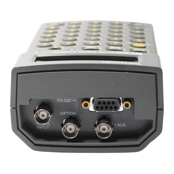
Figure 2: Connecting the SDA601 Connect the instrument as shown in Figure 2. The OPTION connector is reserved for later versions of the instrument. Note that the SDA601 has many capabilities and features, and you may wish to gain familiar-... -
Page 17: Aux Output
H Can contain the On-screen Display (OSD; see page 8), which shows the most recent Watch or Analyze results one page at a time—instead of one item at a time as on the SDA601 display. H With Pulse Cross enabled (see page 24), lets you “see” the contents of the vertical and horizontal interval portions of the serial video signal. -
Page 18: Figure 3: A Printed Analysis Report
Figure 3: A Printed Analysis Report The RS-232 interface is also designed to support in-field upgrade of the operating software. Information regarding any such upgrades will be available from your Tektronix representative or field office. SDA601 Serial Digital Analyzer User Manual... -
Page 19: Keypad And Display Conventions
Keypad and Display Conventions Please see the Instruction card (Tektronix part number 070-8912-00) supplied with your SDA601 for a “tour” of the keypad and an ex- planation of the display symbols. For your convenience, the following panels are taken from the card. -
Page 20: The On-Screen Display (Osd)
The On-screen Display (OSD) The OSD is a 12 line, 24 column display containing results from an SDA601 Analyze or Watch session. It can be superimposed on the AUX output and viewed on an attached video monitor. Toggle the OSD On/Off with the Insert On/Off key. The default OSD will resemble Figure 4 when the instrument is in Watch mode. -
Page 21: Preliminary Settings
The Analyze OSD is similar; see Figure 6, on page 15. Preliminary Settings Once the SDA601 is up and running, you should choose some settings depending on how you’ll be using the instrument. These settings are made through the Utility menu. Invoke the Utility menu by holding... -
Page 22: Set The Battery Type
3. The top item in the Power Manage submenu is Battery Type. Toggle to the selection that matches the type of battery you have " installed in your SDA601 by pressing either . The choices are “rechargeable” and “disposable.” Select rechargeable when using NiCad AA cells or the optional battery pack;... -
Page 23: Disable (Enable) Timed Lcd Backlight Turn Off
Disable (Enable) Timed LCD Backlight Turn Off Another power saving feature of the SDA601 is timed turn-off of the LCD backlight. It is enabled by default in a new or reset instrument. If you will always operate with the AC adapter, you may wish to disable the feature. - Page 24 Getting Started SDA601 Serial Digital Analyzer User Manual...
-
Page 25: Operating Basics
Your SDA601,” below. For additional information on selected top- ics, turn to the Reference section of this manual, beginning on page 27. Using Your SDA601 Here’s what you can do with your SDA601. Instructions for each function begin on the indicated page. SDA601 Serial Digital Analyzer User Manual... -
Page 26: Analyzing A Signal
Review List. The Review List may be viewed on the OSD (on an attached video monitor) as well as on the SDA601 LCD when no menu is active. The up and down arrow keys scroll through the list of de- tected “conditions.”... -
Page 27: Figure 6: The Analyze Osd
Line/field length (OK/incorrect) Performing an Analysis — To analyze a signal, simply press Ana- lyze . The SDA601 will observe the incoming signal for one second, analyze the data, and write the results to a “condition review list” and the OSD. -
Page 28: Watching A Signal
L when an 8-bit video signal is received. Other stuck bits sug- gest either an incorrect signal or faulty equipment. Zero-length ANC — is reported by the SDA601 when an ancillary data “Data Count word” with value Ø is detected. Analyze mode... - Page 29 Zero length ANC (yes/no) EDH flag set/not set When only the Data Value group is set to “Watch,” the SDA601 will actually observe the status of ten conditions—the eight de- fault conditions plus Illegal Values and Video In/Out of Range. If all four groups are selected, all 20 conditions are monitored.
-
Page 30: Figure 7: The Sda601 "Watching" Display
Alarm menu); and the “E” icon will appear when an error is detected. Figure 7: The SDA601 “Watching” Display 4. Review the condition list on the SDA601 LCD by pressing the key until you reach the END OF LIST message. Use to scroll back up the list as desired. -
Page 31: Alarms
254 seconds (254 is the highest count pos- sible), and the last error was detected in the last reported second, 7:12 into the Watch session. A similar format is used on the SDA601 liquid crystal display. Alarms Alarms are enabled through the Alarm menu. When enabled, an alarm is generated when one or more signal conditions or errors are detected by the SDA601 in Watch mode. - Page 32 Log each error — or as many as the printer buffer allows. In- tended for extended monitoring of the signal when few, if any errors are expected. You can leave the SDA601 (powered by the AC adapter) and a printer unattended to log and help diag- nose intermittent problems.
-
Page 33: Displaying The Signal Level
Displaying the Signal Level The relative level of the serial digital input signal is displayed by default on every new (or reset) SDA601. This display can be helpful in identifying points in your system where the signal may be margin- al because of long cable runs or faulty equipment. -
Page 34: Cursor
Review (G) key. The address/coordinates of the word, and its actual hexadecimal val- ue, may be viewed on the SDA601 display, as shown in Figure 10. Figure 10: The Cursor Data Display The first line of the cursor data display contains the hexadecimal values of the selected word and the three that follow it. -
Page 35: Highlighting
Out of range video levels To use Highlighting: 1. Configure the SDA601 to monitor one or more of the above items; see “Watching a Signal” beginning on page 16. 2. Enter the I/O menu (press Shift , then Insert On/Off ). -
Page 36: Pulse Cross
Use Pulse Cross to “see” those conditions. Pulse Cross Pulse Cross is an SDA601 AUX output mode that allows the user to “see” the horizontal and/or vertical intervals, which are normally blanked in serial video monitors. The original four-word timing ref-... -
Page 37: Presets
5. Press any rectangular key to exit the I/O menu. Presets The configuration of the SDA601 at any given time may be saved as a Preset for later recall. Three different configurations can be saved. Using presets, you can easily change between completely different combinations of (for instance) Watch conditions, alarm settings, LCD display options, and AUX output options. -
Page 38: Software Reset
Operating Basics Software Reset To reset the instrument NVRAM and restore the SDA601 to “facto- ry” default settings, select the Factory Reset item in the Utility/Diag- nostics/NVRAM/TIC Dgs submenu. See page 34. NOTE. All user settings and presets will be lost. -
Page 39: Reference
Utility/OSD Setups submenu; see page 32). The aster- " isk will disappear if you press the key once to change the value to 16. It will reappear if you then press Enter to confirm 16 as the new position. SDA601 Serial Digital Analyzer User Manual... -
Page 40: Figure 12: The Osd Setups/Horizontal Position Item
NOTE. In the menu listings that follow, the factory default for each item is the first listed option. Defaults for items that can be set within a range of numeric values are given within square brackets [for example] on the option line. SDA601 Serial Digital Analyzer User Manual... -
Page 41: Watch Menu (Groups Enabled)
Off <> Watch (10) Line/Field Len Off <> Watch Status is reported but not treated as an error. Word length is reported. Missing Ancillary data packet, which is neither Audio nor EDH, is detected. SDA601 Serial Digital Analyzer User Manual... -
Page 42: Alarm Menu
Non- - zero APCRC is reported as an error and will trigger an alarm, if set. Sets all items to Off. Only when alarms are toggled On. Independent of alarm settings. Alarm On/Off Duplicates the action of the key. SDA601 Serial Digital Analyzer User Manual... -
Page 43: I/O Menu
Note that some items in the Diagnostics submenu—are for use by qualified service personnel only (these items are marked with a ¦) symbol); see the SDA601 Service manual (Tektronix part number 070-8914-0x) for instructions on their use. Current time and date, set through the Utility menu. - Page 44 Watch is started or restarted. As selected in item NO TAG. Three end of lines as selected in item NO TAG, may be used as an alternative to Form Feed in order to save paper. SDA601 Serial Digital Analyzer User Manual...
- Page 45 Press Enter Keypad Test Press Enter RS232 loop thru Press Enter Previous Menu Press Enter NVRAM/TIC Dgs.. Press Enter Get TIC Serial Press Enter Get TIC Time Press Enter Read TIC Memory <> 0 * SDA601 Serial Digital Analyzer User Manual...
- Page 46 Write Test Reg tr: 0 <> 255 Will reset the instrument to factory defaults. Value is adjusted during manufacture. To be changed only by qualified service personnel; see the Service manual, Tektronix p/n 070-8914-0x. SDA601 Serial Digital Analyzer User Manual...
-
Page 47: The Aux Output
Previous Menu Press Enter The AUX Output The analog signal present at the SDA601 AUX output is derived from the Serial Video input. It is a single channel, 5-bit decoded and unfiltered, suitable for identifying the input and displaying the cursor cross hairs, Highlighting, and OSD. -
Page 48: Rs-232/Printer Setups
When in doubt, set Parity to None. Using the Watch Mode Here are some notes and hints regarding the use of the SDA601 Watch mode to verify the integrity of Serial Digital Video signals. Format Error Checking... - Page 49 “Video Missing.” In order to reestablish horizontal and vertical synchronization to the input signal, the SDA601 must be able to recognize the presence of EAVs in the incoming signal for 64 consecutive video lines. When this is achieved, then horizontal synchronization is immediately rees- tablished.
-
Page 50: Using The Crc Change Watch Group
Eight-bit signals which are encoded may be used to check either 8-bit equipment or the eight higher-order bits of 10-bit equipment, and 10-bit signals which are encoded may be used to check 10-bit equipment. SDA601 Serial Digital Analyzer User Manual... - Page 51 This allows the check to be used with signals that have constantly changing ancillary data, as do sig- nals that contain embedded audio. With this checking method, data in the vertical and horizontal re- gions is completely unchecked. SDA601 Serial Digital Analyzer User Manual...
- Page 52 Reference SDA601 Serial Digital Analyzer User Manual...
-
Page 53: Appendix A: Characteristics
Appendix A: Characteristics The information in this section is included for the convenience of the SDA601 operator. For a full list of instrument specifications, as well as performance verification and adjustment procedures, please see the SDA601 Service Manual (Tektronix part number 070-8914- NOTE. -
Page 54: Australia / New Zealand Declaration Of Conformity - Emc
Complies with EMC provision of Radiocommunications Act per these standard(s): H AS/NZS 2064.1/2. Industrial, Scientific, and Medical Equipment: 1992 FCC Compliance Emissions comply with FCC 47 CFR, Part 15, Subpart B for Class A equipment. SDA601 Serial Digital Analyzer User Manual... -
Page 55: Specification Tables
300 mV ± 25% Terminated into 75 Ω Sync Amplitude ≤ 500 mV Terminated into 75 Ω DC Offset Quantization 22 mV 75 Ω nominal Impedance ≥ 10 dB to 10 MHz Return Loss SDA601 Serial Digital Analyzer User Manual... -
Page 56: Table 4: Signal Level Meter
Category II (as defined in IEC 1010-1, Annex J) Note: Rated for indoor use only. Pollution Degree Pollution Degree 2 (as defined in IEC 1010-1) Transportation Meets the requirements of NTSB Test Procedure 1A, category II (24 inch drop) SDA601 Serial Digital Analyzer User Manual... -
Page 57: Appendix B: Replaceable Parts
Appendix B: Replaceable Parts The following replaceable parts for the SDA601 are available through your local Tektronix, Inc. field office or representative. It is important when ordering parts to include the following informa- tion in your order: Part number; instrument type and number; instru- ment serial number;... - Page 58 Appendix B: Replaceable Parts Table 7: Power Cords (Cont.) Option Description Part Number Australia power 161-0066-13 Japan power 161-0298-00 China power 161-0304-00 SDA601 Serial Digital Analyzer User Manual...
-
Page 59: Appendix C: User Service
The BATTERY LOW Message The warning “BATTERY LOW” will appear on the second line of the SDA601 display when the battery voltage drops below a prede- termined level. The level depends on the Battery Type setting. The SDA will operate for approximately ten minutes after the message first appears. -
Page 60: Replacing The Batteries Or Battery Pack
Replacing the Batteries or Battery Pack To install AA batteries or the battery pack, open the battery compart- ment of the SDA601 by pressing down on the cover and sliding it in the direction of the inscribed arrow, as shown above. When the cover tabs line up with the slots in the case, lift the cover away from the instrument. -
Page 61: Replacing The Touch Memory/Timer Module
See the Ser- vice manual for performance verification and adjustment procedures. CAUTION. The SDA601 case is made of molded plastic. Do not allow water to get inside any enclosed assembly or component. Do not clean any plastic materials with organic cleaning solvents—benzene,... -
Page 63: Glossary
Audio Engineering Society and European Broadcasting Union. analyze When Analyze is pressed the SDA601 locks to the incoming sig- nal (if possible) and monitors it for one second. The status of a predefined set of signal characteristics (“conditions”) may then be read on the instrument LCD—and the OSD, when an external... - Page 64 A CRC derived from the samples in the active picture only. De- scribed in SMPTE RP 165. In the SDA601, the auxiliary output. The AUX output can be configured as analog “pseudo-video” (unfiltered DAC output) or as the trigger pulse.
- Page 65 “error second” basis. cursor In the SDA601, the “cursor” is used to pinpoint a single word in the digital video frame and discover the actual value of the se- lected word and the three that follow. The location of the cursor may also be shown with “cross hairs”...
- Page 66 Glossary data value group An SDA601 Watch group that contains: G Illegal (data word) values G Video samples in/out of range The data word values are monitored; illegal values and out of range samples are reported on an “error second” basis.
- Page 67 The flags defined in RP-165 are: error detected here; error detected already; internal error detected here; internal error detected already; and unknown error status. EDH Group An SDA601 Watch group that contains: G APCRC EDH errors G FFCRC EDH errors G EDH flags (set/not set) The CRCs and flags are monitored.
- Page 68 See Watch Group. highlighting An SDA601 operating mode in which pixels in the AUX output that correspond to selected error conditions “flash” when that error occurs. Permits visual monitoring of the frequency and placement of the errors in context of the video signal and picture.
- Page 69 OSD (on-screen display) In the SDA601, a 12 line, 24 column character display that may be superimposed on the AUX output and viewed on an attached video monitor. For convenient review of Analysis results and Watch status.
- Page 70 Digital information that is transmitted in serial form. Often used informally to refer to serial digital television signals. SMPTE (Society of Motion Picture and Television Engineers) A professional organization that recommends standards for the television and film industries. SDA601 Serial Digital Analyzer User Manual...
- Page 71 A stuck bit may indicate a defective component in the digital video system “upstream” of the SDA601. synchronous A transmission procedure by which the bit and character stream are slaved to accurately synchronized clocks, both at the receiv- ing and sending end.
- Page 72 “stripped,” or simply ignored. In digital video, 10-bit samples may be truncated for compatibility with 8-bit equipment. Utility Menu The “catch-all” menu of the SDA601 in which seldom-used con- figuration and diagnostic utilities are found. Selected by holding Lock Out down while pressing ON .
Need help?
Do you have a question about the SDA601 and is the answer not in the manual?
Questions and answers