
Related Manuals for Toshiba TDP-MT700


Summary of Contents for Toshiba TDP-MT700
- Page 1 FILE NO. 330-200503 SERVICE MANUAL DLP PROJECTOR TDP-MT700 Document Created in Japan May.,2005...
-
Page 2: Table Of Contents
MT700 Service Manual MT-700 SERVICE MANUAL CAUTION BEFORE SERVICING THE PROJECTOR, READ THE SAFETY PRECAUTIONS IN THIS MANUAL. Contents Safety Precautions ......................2 Servicing Precautions ......................3 Specification ........................4 Circuit Operation ....................... 8 Alignment Procedure....................... 23 Trouble Shooting Guide ....................34 Appendix A: Exploded View.................... -
Page 3: Safety Precautions
MT700 Service Manual 1. Safety Precautions 1. Be sure to read this manual before servicing and save it for future reference. 2. The lamp becomes extremely hot during operation. Allow the projector to cool for approximately 45 minutes prior to removing the lamp assembly for replacement. Do not operate lamps beyond the rated lamp life. -
Page 4: Servicing Precautions
MT700 Service Manual 2. Servicing Precautions 1. When replace the lamp, be sure to avoid burns your fingers because the lamp becomes too hot. 2. Never touch the lamp bulb with a finger or anything else. Never drop it or give it a shock. -
Page 5: Specification
MT700 Service Manual 3. Specification 1.0 Optical Performance Tested under 52” (diagonal) image size unless other specified. Measurement Details refer to Appendix A. 1.1 Lamp OSRAM P-VIP 250 lamp --250W 1.2 ANSI Brightness(Spoke on) Minimum Typical [Base on BenQ RD Meter 800 Lumens 1000 Lumens CL-200]... - Page 6 MT700 Service Manual 1.7.1 White 0.020 1.7.2 Red 0.033 1.7.3 Green 0.020 1.7.4 Blue 0.020 1.7.5 Dark 0.030 2.0 Image Quality 2.1 Throw Ratio 102” ±5% Diagonal at 3m (Wide) 2.2 Zoom Ratio >1.35:1 2.3 Distortion 2.3.1 Horizontal TV Distortion <1.0% 2.3.2 Vertical TV Distortion <1.0%...
- Page 7 MT700 Service Manual level) Standard mode: 28dBA @ 25°C Maximum High mode: 32dBA @ 25°C Standard mode: 29 dBA @ 25°C 6.4 Altitude 0-5999 feet at 30°C 6000-10000 feet at 23°C test 6000 feet above sea level@ 30°C & 10000 feet above sea level@ 23°C only Final data to be confirmed at C3 stage around mid of Nov.
- Page 8 MT700 Service Manual 12.1 D-Sub RGB Input None 12.2 Composite RCA x 1 12.3 S-Video S-Video x 1 12.4 Component RCA x 3 12.5 Progressive component and BNC x 5 DTV RGBHV 12.6 Digital Video HDMI 13.0 Control Interface 13.1 IR Receiver 2 receiver (Front and Rear) 13.2 Serial Input 8 pin Mini-Din (Female) x 1 , Base on RS-232 Standard...
-
Page 9: Circuit Operation
MT700 Service Manual 4. Circuit Operation 4.1. System Block Diagram MT700 consist of the connector, main, chip board. The connector board provides the input terminal and RS-232 for service ,video input(Composite, S-video, YcbCr) and graph input(RGB BNC , Y Pb Pr). The main board provides the A/D converter for the graph input (HDMI, RGB BNC, YPbPr) and decoder function for the video input. - Page 10 MT700 Service Manual HDMI Main Board HDMI Receiver HD2 DMD SDRAM x3 DDC Link EEPROM (2M x 32) (SII9993) (EDID,2K) RGBHV Scalar RGB888 Format Mux 1 YPBPR 1 (RM103) CHIP (AD9883A) AD74132 Mux 1 BOARD YPBPR 2 (AD8183) YCBCR 1 YCBCR 2 YCBCR VIDEO DECODER...
- Page 11 MT700 Service Manual 4.1.1. Main Board 4.1.1.1. Overview 1. The Main Board includes five input connectors. They are HDMI input, component 1 input, component 2 input, S-video input, composite video input, RGBHV input and download connector. 2. The Graphic port input includes (1) HDMI input connector, (2). Component YPBPR1 and (3).
- Page 12 MT700 Service Manual EDID EEPROM (2K) HDMI Receiver D_INA[0..23] D_HSYNC, D_VSYNC (SII9993) To Scalar HDMI DIN_CLK RGBHV Mux 2 YPBPR 1 (AD9883A) Comp 1 (AD8183) Mux 1 YPBPR 2 Comp 2 (AD8183) Hsync, Vsync Hs, Vs RGBHV SCHMITT NAND GATE (74AHCT132) Graphic Port Input Circuits...
- Page 13 MT700 Service Manual 4.1.1.3. Video port input circuit 1. Video decoder SAA7118: The video decoder can accept 480i, 576i via component 1 and component 2 input connectors. It also supports NTSC M, NTSC-J, PAL (included PAL M, PAL N), and SECAM via S-Video connector and composite video connector.
- Page 14 MT700 Service Manual 2. Scalar Rembrandt-103 Rembrandt-103 can process dual channel data: graphic port and video port data. It receives data with YCBCR 4:2:2 (video input) as well as RGB 8:8:8 (graphic input). Rembrant-1’s processing also needs to install 3 set of SDRAM. 3.
- Page 15 MT700 Service Manual 4.1.2. DLP Processor 1. DLP data processor DDP1010: The function block of DDP1010 includes video graphic processing, micro- controller, formatter, real-time control and system support function. DDP1000 accepts RGB 4:4:4 signals from the scalar, and formats the signals into XGA DMD acceptable signals.
- Page 16 MT700 Service Manual The DAD1000 will generate DMD reset signals MBRST[0..15] as well as VCC2 (7.5V) for DMD chip. 4. Motor Controller SH6742: The DDP1010 electronics support driving three phase, 12 poles, Y configuration, brushless DC color wheel motor. The DDP1010 electronics use a combination of back EMF from motor and the CWINDEX signal to frequency and phase lock the color wheel revolution to 2.5 times of VSYNCZ rate.
- Page 17 MT700 Service Manual FAN2_G Reserved CONTROLLER FANSPIN2 (MAX6660AEE) TO THERMAL SENSOR BOARD FAN1_E, FAN1_B FAN1_G To BLOWER ( Inlet ) CONTROLLER FANSPIN1 (MAX6660AEE) TO THERMAL SENSOR FAN3_G BOARD FAN4_E, FAN4_B To MAIN CONTROLLER FANSPIN3 (ON LAMP BOX) (MAX6660AEE) FAN4_G To DMD IIC (SDA, SCL) CONTROLLER IIC level shift...
- Page 18 MT700 Service Manual 4.1.3. Power Supply Circuits 4.1.3.1. Block Diagram 4.1.3.2. General specification Input voltage : AC 90~264V Input Frequency: 47~63Hz Input power: 330W max The power circuit shall supply DC power outputs as followings: Outpu Nominal MAX. Load Current...
- Page 19 MT700 Service Manual 4.1.4. Circuit Operation Theorem 4.1.4.1. EMI filter EMI components have CM inductor,DM inductor,CX1,CX2,CY1, and CY2 1. CM inductor:To be used the High μFerrite core,and the inductance is high (~mH or more 10mH) 2. DM inductor:To be used the low μ Iron poweder core ,and the inductance is lower(10uH or more 100uH) 3.
- Page 20 MT700 Service Manual 4.1.4.2. Bridge rectifier and filter Bridge convert the AC input into DC output ,and the CAP is AC filter. 4.1.4.3. Power Factor Correction The Power Factor Correction (PFC) like a Boost converter . The AC mains voltage is rectified by a bridge and the rectified voltage delivered the the boost converter .
- Page 21 MT700 Service Manual 4.1.5. SPS BLOCK DIAGRAM 4.1.5.1. Snubber circuit The snubber circuit, which is reduce the spike voltage .This had its benefits in the Safe Operating Area (SOA) of the semiconductors ,and it lowers the spectral content if any radiated RFI thus radiating less RF energy.
- Page 22 MT700 Service Manual 4.1.5.2. Flyback Circuit In a flyback converter operated in the discontinuous mode, the energy stored in the flyback transformer must be zero at the beginning and end of each swiching period. During the on-time energy is stored in the transformer and energy taken from the transformer when the switching transistor turn-off, the stored energy is all delivered to the output.
- Page 23 MT700 Service Manual 4.1.5.4. Voltage Feedback The seconddary referenced error amplifier control system is implemented with the TL431. The device consists if an accurate 2.5V reference, error amplifer a, and driver. The output voltage is sensed , diveded by R5 and R6 ,and applied to the inverting of the error amplifier is internally connected to the reference voltage .
-
Page 24: Alignment Procedure
MT700 Service Manual 5. Alignment Procedure 5.1. DMD Bias Voltage Alignment • Check the Label on DMD Chip Ex : 5954604 – 2118C (Four Types B,C,D,E) • Switch the DIP Switch on DMD Board according to the Red character (XGA) (SVGA) 5.2. - Page 25 MT700 Service Manual 5.2.2. Use RS232 Code Function Comment Z011 User brightness User's picture settings Z012 User contrast User's picture settings Z013 User intensity User's picture settings Z014 User color User's picture settings Z015 User tint User's picture settings Z016 User sharpness User's picture settings Z017 Color temperature User's picture settings...
- Page 26 MT700 Service Manual Z052 YPbPr input -- Pb offset Graphic signal adjustment Z053 YPbPr input -- Pr offset Graphic signal adjustment Z054 Frequency Graphic signal adjustment Z055 Phase Graphic signal adjustment Z056 Horizontal postion Graphic signal adjustment Z057 Vertical position Graphic signal adjustment Z058 Clamp placement Graphic signal adjustment...
- Page 27 MT700 Service Manual Z106 Gamma gain -- Blue Gamma correction Z107 Gamma offset -- Red Gamma correction Z108 Gamma offset -- Green Gamma correction Z109 Gamma offset -- Blue Gamma correction Z121 DLP Contrast -- Red Gamma correction Z122 DLP Contrast -- Green Gamma correction Z123 DLP Contrast -- Blue Gamma correction...
- Page 28 MT700 Service Manual 5.2.3. The normal point Higher Lower Normal...
- Page 29 MT700 Service Manual 5.2.4. MT700 Color Alignment 1. Load All User default 2. Load Factory default 3. Adjust Color wheel delay 4. Restore color Temperature 0-5 to default for data and video color temperature...
- Page 30 MT700 Service Manual 5. ADC setting 5.1 YPbPr input Timing: 480P Pattern: SMPTE (DVD Disk) Switch 0 or 7.5 IRE (Projector and DVD recorder’s IRE must be synchronized) The ideal environment to adjust the brightness and contrast value is in the dark room. Adjust the ADC brightness value to make the left column to darkest to get the best brightness result.
- Page 31 MT700 Service Manual...
- Page 32 MT700 Service Manual 5.2 GBRHV input Timing :XGA Pattern :SMPTE (DVD Disk) The ideal environment to adjust the brightness value is in the dark room. Offset-R, Offset-G, Offset-B Adjust the ADC Offset-R, Offset-G, Offset-B value to make the left column to darkest, to get the best brightness result.
- Page 33 MT700 Service Manual 5.3 YCbCr input Timing :480i Pattern :SMPTE (DVD Disk) Switch 0 or 7.5 IRE (Projector and DVD recorder’s IRE must be synchronized) The ideal environment to adjust the brightness and contrast value is in the dark room. Adjust the ADC brightness value to make the left column to darkest, to get the best brightness result.
- Page 34 MT700 Service Manual 5.4 S-Video input Timing :480i Pattern :SMPTE (DVD Disk) Switch 0 or 7.5 IRE (Projector and DVD recorder’s IRE must be synchronized) The ideal environment to adjust the brightness and contrast value is in the dark room. Adjust the ADC brightness value to make the left column to darkest, to get the best brightness result.
-
Page 35: Trouble Shooting Guide
MT700 Service Manual 6. Trouble Shooting Guide 6.1. System LED Message Thermal After error Note turn on SW/off step 3 ( finish again ? step 1 step 2 (cooling) cooling ) Power Lamp Temp Power Lamp Temp intake sensor blink Shutdown over heat orange Off... - Page 36 MT700 Service Manual Lamp life warning Note After turn on SW/off Power Lamp Temp OSD message again ? Lamp hour (P- ON) 1950 ~ Action 2000 Lamp hour (P- OFF) 1950 ~ Action 2000 Lamp hour (P- blink Lamp exceed service ON) 2000 ~ green hours.
- Page 37 MT700 Service Manual Keypad LED no displayed Change AC inlet Check thermal breaker cable Change Keypad Check Keypad Board Board Change PWR Board Change PWR Board Change Main Board...
- Page 38 MT700 Service Manual Temp. LED Error (Temp error massage) Abnormal Enter the factory mode fan control menu check Change the Thermal temp. range is normalor abnormal. The Temp. sensor Board must between 0 to 90 Normal Change Main Board Fan Error message Good Check Which fan no spin Change Main board...
- Page 39 MT700 Service Manual Lamp Error Color wheel Check PWR/B PWR/B NG DC 360V spin? Check C/W M/B NG Index Sensor/B or wire Lamp or Ballast NG...
- Page 40 MT700 Service Manual The image exist virtical or horizontal bar always Check the connection between chip board Plug in the and Main board connecter again Good Check the chip board Change the is good or not Chip board Good Change the Check the DMD socket DMD socket Change the Main board...
-
Page 41: Appendix A: Exploded View
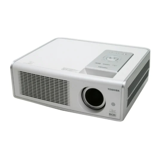
MT700 Service Manual Appendix A: Exploded View 1. The appearance of projector... - Page 42 MT700 Service Manual 2. The front side of projector Thermal Breaker Ballast Lamp Module Main Board E05 (2) Thermal Sensor E05 (1) Zoom Assy Thermal Sensor...
- Page 43 MT700 Service Manual 3. The rear side of the projector Blower Connector BD Module Connector Board Main power supply Terminal Cover...
- Page 44 MT700 Service Manual 4. Side view of the projector Lamp Cover 5. Top View of the projector Key Pad IR Board...
- Page 45 MT700 Service Manual 6. Optical Unit Engine Sensor board Color wheel PCBA Chip Board Focus Ring DMD Chip Zoom Ring...
- Page 46 MT700 Service Manual 7. Packing Materials and Accessory...
-
Page 47: Appendix B: Spare Parts List
ZOOM ASSY 23587534 DIGITAL MICRO MIRROR DEVICE, HD2 VALUE 23587535 PC BOARD ASSY, SNS-B, TDP-MT700 23587541 COLOR WHEEL ASSY, DIA50 PE7700 PRPDISC. TDP-MT700 23587542 PC BOARD ASSY, LAMP, TDP-MT700 23587543 LOWER COVER ASSY, TDP-MT700 23587544 PC BOARD ASSY, MAIN, TDP-MT700... - Page 48 MT700 Service Manual Appendix C: OSRAM Lamp Date Code Year 2005 2006 2007 2008 2009 Month...
- Page 49 T O S H I B A C O R P O R A T I O N 1- -1, SHIBAURA 1- - CHOME, MINATO - - KU, TOKYO 105 -- 8001, JAPAN...
Need help?
Do you have a question about the TDP-MT700 and is the answer not in the manual?
Questions and answers