
Related Manuals for Erskine Attachments 965RM


Summary of Contents for Erskine Attachments 965RM
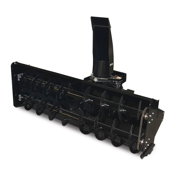
- Page 1 Model 965RM-1085RM Rear Mounted – CAT. II or III 3-Point Snowblower Tractors 50-100 HP Operator’s Manual Set-Up Assembly Maintenance Parts Information Read this Manual Before Use...
-
Page 2: Table Of Contents
Serial Number………….._____________ YOUR ATTACHMENTS DEALER ADDRESS: PHONE: CONTACT: NOTE: Erskine Attachments LLC reserves the right to make improvements in design or changes in specifications at any time without notice and without incurring any obligations to install them on units previously sold. -
Page 3: Safety
Indicates potentially Erskine Attachments LLC cannot anticipate every hazardous situation which, if not avoided, possible circumstance that might involve potential will result in death or serious injury. hazard. The safety messages found in this manual ... - Page 4 Escaping fluid under pressure can Do not modify equipment or add attachments that penetrate the skin causing serious are not approved by Erskine Attachments LLC. injury. Use adequate safety warning lights and devices as Avoid the hazard by relieving the required by local regulations.
- Page 5 SERIAL NUMBER AND SAFETY DECAL LOCATIONS Serial Number Location: It is important to refer to the serial number of the attachment when making repairs or ordering parts. Early or later models (identification made by serial number) may use different parts, or it may be necessary to use different procedures in doing a specific operation.
- Page 6 SERIAL NUMBER AND SAFETY DECAL LOCATIONS________ Safety Decals Locations: The locations of the safety decals are shown. If these decals are missing, damaged, or painted over they must be replaced. Call Erskine Attachments LLC (218-435-4045) for replacement decals. Part number: 310820 Part number: 200001...
-
Page 7: Set-Up Assembly
SET-UP ASSEMBLY Discharge Chute Installation 1. Remove the roller guide opposite the rotation motor from the blower housing by removing the bolt securing the roller guide to the snowblower. 2. Remove the chain cover from the blower housing by removing the two bolts securing the cover to the snowblower. - Page 8 SET-UP ASSEMBLY Cylinder and Hose Installation The chute rotator hydraulic hoses (and optional chute deflector hoses, equipped) shipped preassembled from the factory. If the hoses are disconnected for any reason, make sure that the restrictor fitting is kept in the hydraulic orbit motor. IMPORTANT: Properly route the hoses to prevent them from being damaged when the snow blower is raised and lowered.
- Page 9 SET-UP ASSEMBLY Mounting and Adjusting the Snowblower 1. The snowblower mounting arms are designed to be mounted on standard Category II and narrow Category III 3-point hitch systems. They are also quick hitch compatible. The arms are set at the factory in the innermost position, which should work for most 3-point quick hitch systems.
- Page 10 SET-UP ASSEMBLY 4. After the snowblower tilt is determined and set, the driveline telescoping length must be checked. 5. With the snowblower resting on the ground, connect the driveline to the tractor PTO shaft and mark the location of the overlap on the driveline. Also check that there is sufficient clearance between the driveline and the tractor drawbar.
- Page 11 SET-UP ASSEMBLY 9. With the operator in the seat of the tractor and the seat belt fastened, start the engine. With the engine at an idle, check that the hydraulic functions are working properly by rotating the chute all the way in both directions and angling the chute deflector all the way up and down (if hydraulic chute deflection kit is equipped).
-
Page 12: Mounting Instructions
MOUNTING INSTRUCTIONS After the initial set-up is complete, use the following instructions to mount the snowblower to the tractor. 1. With the operator in the seat of the tractor and the seat belt fastened, back the tractor up to the snowblower, aligning the 3-point arms with the snowblower arms. -
Page 13: Operating Instructions
OPERATING INSTRUCTIONS Know your work area. Avoid obstructions and debris. 1. Before starting the tractor engine, check that the snowblower is either level or tilted slightly away from the tractor. This creates a straighter driveline angle, and can be accomplished by lengthening the tractor’s 3-point top link (refer to tractor’s operator’s manual for top link adjustment instructions). - Page 14 OPERATING INSTRUCTIONS 4. With the operator in the operator’s position, check 9. Increase the tractor engine speed to full throttle. to be sure all operating controls are in neutral and Always operate the snowblower with the engine at start the engine. full throttle for maximum efficiency.
- Page 15 _____________________ROUTINE MAINTENANCE________________ Lower the attachment to rest flat on the ground, disengage the PTO drive, shut down the engine, relieve hydraulic pressure to the attachment, set the park brake, and wait for all motion to stop before leaving the operator’s position or approaching the attachment to perform service of any kind. It is the operator’s responsibility to make daily inspections of the tractor and attachment for damage, loose bolts, fluid leaks, or anything else that could cause a potential service or safety problem.
-
Page 16: Routine Maintenance
ROUTINE MAINTENANCE Grease the auger drive shaft U-joint every 40 hours of operation. Grease each of the four roller guide zerks every 40 hours of operation. Use clean engine oil or roller chain lubricant to lubricate the chute rotator chain every 40 hours of operation. - Page 17 ROUTINE MAINTENANCE Grease the bearings on each end of the augers every 80 hours of operation. IMPORTANT: Do not over-grease the auger bearing units. Excessive grease can cause premature failure. Only add two pumps of grease to each bearing at each greasing interval. Grease the bearing on the end of the auger drive shaft every 80 hours of operation.
- Page 18 ROUTINE MAINTENANCE Gearbox Fluid Check and Fill Parallel GB The gearbox is a combination gearbox consisting of a parallel shaft gearbox that reduces the input speed Vent and a right angle gearbox that drives the fan and auger. This gearbox is designed to be used with 1000 RPM input speed only.
- Page 19 ROUTINE MAINTENANCE Auger Drive Chain Adjustment A properly tensioned auger drive chain will extend the roller chain life. To adjust the chain tension: 1. Loosen the locking bolt, and push the bolt down to move the tension idler down until all slack is removed from the chain.
- Page 20 ROUTINE MAINTENANCE Auger Shaft Shear Coupler The auger drive is shear bolt protected in the event that the auger should strike a solid object. The auger driveshaft shear coupler is located on the left side of the gearbox, under the shield. If sheared, align the holes in the coupler flange and install a 5/16”...
-
Page 21: Bolt Torque Information
BOLT TORQUE INFORMATION... -
Page 22: Parts Information
PART NO. DESCRIPTION STOCK NO. 311900 BODY 965 X 96 CCW W/A 311901 BODY 1085 X 108 CCW W/A 311904 ARM PUSH 965RM W/A 310574 DEFLECTOR LINKAGE BRKT W/A ELEC. DEFLECTOR PKG 310403 CHUTE 12" FM/RM W/A 315067 CHUTE DEFLECTOR W/A... - Page 23 ELEC. DEFLECTOR PKG 33010 WASHER FLAT 7/16" 33016 WASHER FLAT 5/8" 36314 NUT HEX FULL 5/8" NC 965RM ONLY 36314 NUT HEX FULL 5/8" NC 1085RM ONLY 37216 NUT REV LOCK 5/8 NC 13209 BOLT HEX 1/2 X 1‐1/2 NC GR 5...
- Page 24 PARTS INFORMATION ITEM PART NO. DESCRIPTION STOCK NO. 311902 AUGER 16D X 96 W/A 311903 AUGER 16D X 108 W/A 201097 FAN 30D 960FM 2.0 CCW W/A 104713 BRG 1‐1/2 4‐B FLG 311716 AUGER DS 14S 21T X 37.75 925 311735 AUGER DS 14S 21T X 44.12 1085 310652...
- Page 25 PARTS INFORMATION Add 96oz. of 80W-90 to Right Angle Gearbox Add 40oz. of 80W-90 to Parallel Gearbox...
- Page 26 PARTS INFORMATION ITEM PART NO. DESCRIPTION STOCK NO. 201666 DRIVELN 55S 21T X 20T X 35.75 1000S PTO 201667 DRIVELN 55S 20T X 20T X 35.94 1000L PTO 202196 YOKE 55S IMP SHEAR 1 1/2‐23SPL 104274 REPAIR KIT U‐JOINT 55S 201664 YOKE 55S SLIDE LK 1 3/8 21 SPL 1000S PTO...
- Page 27 PARTS INFORMATION ITEM PART NO. DESCRIPTION STOCK NO. 103318 ADPT STR 2MP-2FPX HYD DEFLECTOR PKG 320064 ADPT REST ELB 2MP-2FPX-90-1/16 HYD DEFLECTOR PKG 320659 ADPT RESTRICTOR 10MB-6MJ-1/32 201522 ADPT STR 10MB-6MJ 320623 COUPLER HYD 1/2-8FP M PPT 311745 HOSE 1/4 X 90 8MP-6FJX90 310891 HOSE 1/4 X 104 8MP-2MP HYD DEFLECTOR PKG...
- Page 28 PARTS INFORMATION ITEM PART NO. DESCRIPTION STOCK NO. 320689 CASTING GEARBOX 900 GB 300632 590 GEARBOX CASE 300633 590 GEARBOX CASE 300634 GEARBOX COVER 300635 GEARBOX COVER 320690 COVER HOUSING (CLOSED) 900 GB 300636 COVER ADAPTOR 300637 GEAR 46T 23T 12/24 320688 GEAR BEVEL 16T 900 GB 300638...
- Page 29 PARTS INFORMATION...
-
Page 30: General Specifications
GENERAL SPECIFICATIONS Model 965RM 1085RM Stage 96” 108” Cutting Width 36” 36” Cutting Height Up to 50’ Up to 50’ Casting Distance 30” 4-blade 30” 4-blade Fan Diameter (shear bolt protected) (shear bolt protected) 16” dual open flyting 16” dual open flyting... - Page 31 Erskine Attachments LLC to improve its products whenever it is possible and practical to do so. Erskine Attachments LLC reserves the right to make changes and or add improvements at any time without incurring any obligation to make such changes or add such improvements to products previously sold.
- Page 32 P/N 311955 Date Printed: 8/26/2020 Printed in U.S.A. Erskine Attachments LLC...
Need help?
Do you have a question about the 965RM and is the answer not in the manual?
Questions and answers