Advertisement
Quick Links
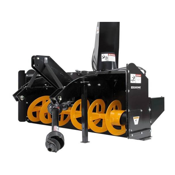
Models 620RP - 725RP - 825RP
Snow Blowers
Read the Operation & Maintenance Manual entirely. When you see this
symbol, the subsequent instructions and warnings are serious – follow
without exception. Your life and the lives of others depend on it!
Rear Pull – CAT I 3 Point
Operator's Manual
Set-Up Assembly and
Parts Information
D
D
o
o
n
n
o
o
t
t
u
u
s
s
e
e
o
o
r
r
o
o
p
p
e
e
r
r
a
a
t
t
e
e
t
manual has been read and understood.
t
h
h
i
i
s
s
m
m
a
a
c
c
h
h
i
i
n
n
e
e
u
u
n
n
t
t
i
i
l
l
t
t
h
h
i
i
s
s
Advertisement

Subscribe to Our Youtube Channel
Related Manuals for Erskine Attachments 620RP


Summary of Contents for Erskine Attachments 620RP
- Page 1 Models 620RP - 725RP - 825RP Rear Pull – CAT I 3 Point Snow Blowers Operator’s Manual Set-Up Assembly and Parts Information manual has been read and understood. Read the Operation & Maintenance Manual entirely. When you see this symbol, the subsequent instructions and warnings are serious – follow...
- Page 2 Good safety practices not only protect you, but also the people around you. NOTE: Erskine Attachments LLC reserves the right to make improvements in design or changes in specifications at any time without notice and without incurring any obligations to install them on...
-
Page 3: Table Of Contents
TABLE OF CONTENTS FOREWORD SAFETY SERIAL NUMBER/DECAL LOCATION MOUNTING INSTRUCTIONS OPERATING INSTRUCTIONS 9-10 ROUTINE MAINTENANCE 11-16 SET UP ASSEMBLY 17-23 PARTS INFORMATION 24-31 GENERAL SPECIFICATIONS WARRANTY REFERENCE INFORMATION Write the serial number for your attachment in the spaces below. Always refer to this serial number when calling for service or parts. -
Page 4: Foreword
Erskine Attachments LLC cannot anticipate every possible circumstance that might involve potential The signal words CAUTION, WARNING, or hazard. The safety messages found in this manual... -
Page 5: Safety
Know how to stop all equipment • Do not modify equipment or add attachments that operation in case of emergency. are not approved by Erskine Attachments LLC. • Avoid the possibility of personal injury and/or • Remember, YOU are responsible for the safe machine damage. - Page 6 SERIAL NUMBER AND SAFETY DECAL LOCATIONS ________ Serial Number Location: It is important to refer to the serial number of the attachment when making repairs or ordering parts. Early or later models (identification made by serial number) may use different parts, or it may be necessary to use different procedures in doing a specific operation.
- Page 7 Model No. 300794 The locations of the safety decals are shown. If these Location: Back RH of blower assembly decals are missing, damaged, or painted over they Quantity: 1 must be replaced. Call Erskine Attachments LLC (218-435-4045) for replacement decals.
- Page 8 PTO shaft. IMPORTANT: Maximum driveline extension is 9 inches (230.4mm) for the 620RP, and 17 inches (431.8mm) for the 725RP and 825RP. This allows for a minimum overlap of 5 inches (127mm).
- Page 9 OPERATING THE SNOW BLOWER WARNING: DO NOT operate from any position except seated in the operator’s seat with the seat belt fastened. DO NOT permit riders. 1. Before starting the tractor, check to see that the blower is nearly level to the ground. This creates a straighter driveline angle and can be accomplished by adjusting the tractor’s upper 3-...
- Page 10 OPERATING THE SNOW BLOWER_______________ 4. Check to be sure all tractor-operated controls 8. Engage the tractor PTO system (see tractor are in the neutral position and start the engine. operating manual). CAUTION: Be sure all by-standers are IMPORTANT: To prevent the possibility of damage, clear of the equipment before starting.
- Page 11 ROUTINE SNOW BLOWER MAINTENANCE It is the operator’s responsibility to make daily inspections of the tractor and attachment for damage, loose bolts, fluid leaks, or anything else that could cause a potential service or safety problem. Preventive maintenance is the easiest and least expensive type of maintenance. IMPORTANT: Bolts and set screws can loosen after initial usage.
- Page 12 ROUTINE SNOW BLOWER MAINTENANCE____________ LUBRICATION (continued) Grease the PTO driveline U-joints and telescoping slide after every 4 hours of use. Only grease the telescoping slide with the driveline compressed. Grease the bearing on the front end of the fan shaft after every 40 hours of operation.
- Page 13 ROUTINE SNOW BLOWER MAINTENANCE____________ AUGER DRIVE CHAIN ADJUSTMENT A properly tensioned auger drive chain will extend the roller chain life. To adjust the chain tension, loosen the locking bolt and push the chain tightener bracket down until all slack in the chain is removed. After adjustment, tighten the locking bolt to prevent the roller from rotating.
- Page 14 ROUTINE SNOW BLOWER MAINTENANCE PTO DRIVELINE SHEAR BOLT REPLACEMENT The PTO driveline shear coupler is located on the tractor PTO coupler. 1. Align the holes in the coupler flange. 2. On all models install one 3/8” x 1” grade 2 bolts with lock nuts.
- Page 15 ROUTINE SNOW BLOWER MAINTENANCE____________ DISCHARGE CHUTE ROTATOR ADJUSTMENT (continued) Manual Rotation To adjust the discharge chute cable: 1. Rotate chute all the way to side needing adjustment. 2. Loosen the setscrew holding the cable in place. 3. Using pliers, pull the cable through the hole until the cable is tight.
-
Page 16: Set Up Assembly
SET UP ASSEMBLY UNCRATING AND SETUP Remove the crate and supporting wood brackets. Bolt the hand crank support bracket to the upper arm and insert the crank tube. Bolt the lower end of the crank tube to the spool. The crank handle length is adjustable. - Page 17 SET UP ASSEMBLY_______________________ MANUAL ROTATION CHUTE INSTALLATION Remove one of the roller guides from the blower housing by removing the bolt securing the roller guide. After unpacking the chute, slip the chute into the grooves on the two remaining roller guides. Install the roller guide and bushings with bolt and lock nut.
- Page 18 SET UP ASSEMBLY_______________________ MANUAL DISCHARGE CHUTE INSTALLATION (continued) Thread cable through cable guide as shown. Turn crank handle clockwise to wind up the cable on the lower part of the spool as shown. Keep tension on the loose end of the cable while cranking so the cable on the spool doesn’t unwind.
- Page 19 SET UP ASSEMBLY HYDRAULIC DISCHARGE CHUTE INSTALLATION Remove one of the roller guides from the blower housing by removing the bolt securing the roller guide. Remove the chain shield from the blower housing. After unpacking the chute, slip the chute into the grooves on the two remaining roller guides.
- Page 20 SET UP ASSEMBLY______________________ DRIVELINE INSTALLATION Install keyed yoke of the driveline onto the snow blower gear box shaft with a 3/8” x 2” key. Secure with 3/8” grade 5 bolt and tighten set screw. WARNING: Be sure the PTO master shield is secured in its operating position.
- Page 21 SET UP ASSEMBLY MOUNTING AND ADJUSTING BLOWER TO TRACTOR 1. The mounting arms of the 620RP, 725RP and 825RP are designed to be used on the standard category I 3-point hitch. They are also quick hitch compatible. Be sure to pay extra attention to the driveline length when using a quick hitch.
- Page 22 SET UP ASSEMBLY_______________________ MOUNTING AND ADJUSTING BLOWER TO TRACTOR (continued) 4. After snow blower backward tilt determined and set, the driveline telescoping length must be checked. First, with the blower on the ground, connect the driveline coupler to the tractor PTO shaft and mark the location of overlap on the driveline.
- Page 23 SET UP ASSEMBLY MOUNTING AND ADJUSTING BLOWER TO TRACTOR (continued) 7. With the engine idling, engage the PTO drive and apply power slowly to the snow blower. If there is any roughness or excessive noise, stop the blower, shut down the tractor engine and find the cause.
- Page 24 620/725/825 REARPULL BODY INFORMATION___________ ITEM PART NO. DESCRIPTION STOCK NO. 620 REARPULL MODEL 310801 BODY T20 X 60 CCW W/A 310802 BODY T24 X 72 CCW W/A 725 REARPULL MODEL 310803 BODY T24 X 84 CCW W/A 825 REARPULL MODEL 310821 MOUNT REARPULL T20 W/A 620 MODEL ONLY...
- Page 25 620/725/825 REARPULL BODY INFORMATION__________...
- Page 26 620/725/825 REARPULL BODY INFORMATION__________ ITEM PART NO. DESCRIPTION STOCK NO. 310827 FRAME ARM REARPULL T20LH W/A 620 MODEL ONLY 311419 FRAME ARM REARPULL T24 LH W/A 725 & 825 MODELS ONLY 37212 NUT HEX LOCK 3/8 NC 37214 NUT HEX LOCK 1/2 NC 33626 WASHER LOCK...
- Page 27 620/725/825 REARPULL BODY INFORMATION________...
- Page 28 AUGER DS 825 1.25 X 39.5 RAW W/A REPLACED 310879 OCT 2016 37211 NUT REV LOCK 5/16 NC GR 5 COMES WITH SHAFT 201384 BOLT HEX 5/16 X 1-1/4 NC GR 2 COMES WITH SHAFT 64137 PIN ROLL 3/16 X 1-1/2 FOR 620RP AND 725 RP ONLY...
- Page 29 620/725/825 REARPULL DRIVE INFORMATION VIEWED FROM TOP VIEWED FROM FRONT...
- Page 30 620/725/825 REARPULL DRIVELINE INFORMATION ITEM PART NO. DESCRIPTION STOCK NO. 320148 DRIVE LINE 35S (BLACK) WEASLER 725 & 825 MODELS ONLY 620 MODEL ONLY 320149 DRIVE LINE 14S (BLACK) WEASLER 320241 YOKE ASSM BALL SHR 14S 620 MODEL ONLY 320371 YOKE ASM BALL SHEAR 35S 1 3/8S 725 &...
- Page 31 620/725/825 REARPULL HYDRAULIC INFORMATION ITEM PART NO. DESCRIPTION STOCK NO. 103318 ADPT STR 2MP-2FPX OPT HYD DEFLECTOR PKG OPT HYD DEFLECTOR PKG 320064 ADPT REST ELB 2MP-2FPX-90-1/16 320659 ADPT RESTRICTOR 10MB-6MJ-1/32 OPT HYD ROTATION PKG 201522 ADPT STR 10MB-6MJ OPT HYD ROTATION PKG OPT HYD DEFLECTOR PKG 201522 ADPT STR 10MB-6MJ...
- Page 32 620/725/825 REARPULL OPTIONAL INFORMATION ITEM PART NO. DESCRIPTION STOCK NO. 315875 BRACKET URETHANE 57 W/A WITH OPT. URE/RUB PKG 315876 BRACKET URETHANE 69 W/A WITH OPT. URE/RUB PKG 315878 BRACKET URETHANE 81 W/A WITH OPT. URE/RUB PKG 315459 CUTTING EDGE URETHANE 57 OPTIONAL URETHANE PKG 315460 CUTTING EDGE URETHANE 69...
- Page 33 620/725/825 REARPULL OPTIONAL PARTS INFORMATION ITEM QTY PART NO. DESCRIPTION STOCK NO. 1 1 311703 FRAME REAR BLADE 72 W/A 1 311704 FRAME REAR BLADE 84 W/A 2 1 100302 KIT MARKER ROD SNOWBLADE INCLUDES HWD 3 4 13055 BOLT 5/16 X 1 NC GR 5 PARTS ONLY 4 4 37211 NUT REV LOCK 5/16 NC GR 5 PARTS ONLY 5 2 400074 CYLINDER 2 X 4 B‐B 6 ...
-
Page 34: General Specifications
GENERAL SPECIFICATIONS___________________ Model 620RP 725RP 825RP Stage Working Width 60” 78” 90” Overall Width 62" 78" 90" Length 48" 56" 56" Height 63" 67" 67" Cutting Height 27” 29” 32” Fan Diameter 20” 4-blade 24” 4-blade 24” 4-blade Auger Diameter 16”... -
Page 35: Warranty
Erskine Attachments LLC to improve its products whenever it is possible and practical to do so. Erskine Attachments LLC reserves the right to make changes and or add improvements at any time without incurring any obligation to make such changes or add such improvements to products previously sold. - Page 36 P/N 300620 Date Printed: 2/27/2017 Erskine Attachments LLC Printed in U.S.A.
Need help?
Do you have a question about the 620RP and is the answer not in the manual?
Questions and answers