Table of Contents
Advertisement
Advertisement
Table of Contents

Related Manuals for Vertiv Liebert PEX3 DX Series


Summary of Contents for Vertiv Liebert PEX3 DX Series
- Page 1 Liebert® PEX3 DX Series Precision Air Conditioning User Manual...
- Page 2 Homepage: www.vertiv.com E-mail: support@Vertiv.com Customer service hotline: 4008876510 Asia Pacific Homepage: www.vertiv.com. E-mail: overseas.support@Vertiv.com Australia Customer service hotline: 1300367686 New-Zealand Customer service hotline: 0800100877 For Technical Support, users may contact the nearest Vertiv Co. local sales office or service centre.
- Page 3 Please read this manual carefully before installing, maintaining, and troubleshooting. Liebert PEX3 DX series precision CRAC is a professional device, only professionals are permitted to access the unit and is kept in a place where access is restricted to common people.
- Page 4 Safety Precautions and Measures The important safety precautions and measures that should be followed during the installation and maintenance are described in the following sections. Read the manual prior to installation and operation of the unit. Only qualified personnel should move, install, or service this equipment.
- Page 5 Therefore, care should be taken to ensure that the unit is not located directly above any equipment that could sustain damage due to water and excessive moisture. Use of a leak detection system for the unit and system supply lines are recommended by Vertiv Co.
-
Page 6: Table Of Contents
1.5.10. Fire Detectors ......................................10 1.5.11. Supply Air Pressure Sensor ................................10 1.5.12. Supply Air Temperature Sensor ...............................10 1.6. Refrigerant Requirement ....................................10 1.6.1. Charging Refrigerant ....................................11 1.7. Storage & Operating Environment Requirements ........................12 Vertiv | Liebert® PEX3™ Series Precision Air Conditioner | User Manual... - Page 7 2.3.11. Connection of Copper Pipe (Discharge and Liquid pipe) between Indoor and Outdoor Unit .................................41 2.3.12. Height Difference Requirements and Equivalent Length Calculation ..........43 2.3.13. Pipe Installation Unit (Water-cooled unit) ........................44 Vertiv | Liebert® PEX3™ Series Precision Air Conditioner | User Manual...
- Page 8 3.3.1. Powering-On iCOM and Logging-in/ Unlocking Controls ................63 3.3.2. Powering-on the Thermal Management Unit ......................63 3.3.3. Powering-Off the Thermal Management Unit......................65 3.3.4. Logging Out ........................................65 3.3.5. Setting the Date and Time ................................66 Vertiv | Liebert® PEX3™ Series Precision Air Conditioner | User Manual...
- Page 9 4.1. LCD Screen ...........................................75 4.2. Button and Indicator Panel ..................................75 4.3. Structure Chart of Control Menu ................................77 4.4. Start-Up Interface .........................................78 4.5. Main Interface ...........................................78 4.6. User Menus ..........................................79 4.7. Password ............................................80 Vertiv | Liebert® PEX3™ Series Precision Air Conditioner | User Manual...
- Page 10 6.5. Appearance Inspection and Maintenance of Controller Components ............94 6.6. Air-Cooled Condenser Maintenance Guide ..........................95 6.7. Water-Cooled Condenser Maintenance Guide ........................95 6.8. Filter Maintenance Guide .....................................96 6.9. Infrared Humidifier Maintenance Guide ............................97 Vertiv | Liebert® PEX3™ Series Precision Air Conditioner | User Manual...
- Page 11 Appendix IV: Menu Structure of iCOM Controller (Users Menus) .................109 Appendix V: Table Names and Content of Harmful Substances in Products ......................................110 Appendix VI: Routine Maintenance Inspection Items (Monthly) ...............................................111 Appendix VII: Routine Maintenance Inspection Items (Semi-Annual) ...........................................112 Vertiv | Liebert® PEX3™ Series Precision Air Conditioner | User Manual...
-
Page 12: Chapter 1: Product Overview
The Liebert PEX water-cooled series air conditioner uses integrated structure and highly effective brazed-plate heat exchanger (BPHE), thus it is a compact, efficient and quiet in the operating conditions (only P1030 unit). Vertiv | Liebert® PEX3™ Series Precision Air Conditioner | User Manual... -
Page 13: Model Description
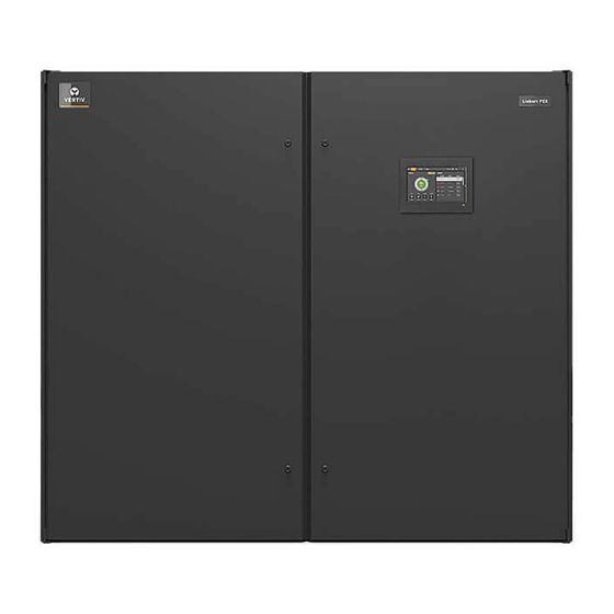
The appearance of Liebert PEX3 models are shown in Figure 1-1. Upflow Model Downflow Model Figure 1-1 Liebert PEX3 Models Vertiv | Liebert® PEX3™ Series Precision Air Conditioner | User Manual... -
Page 14: Model Nomenclature
A+N+S Infrared Humidifier A+H+N Electrode Humidifier A+F+N Digit 12 Display Digit 21 Packaging 9-inch HMI Display Package- Standard Cardboard and Wooden Pallet Small Display Packaging– Wooden Crate Large Display Vertiv | Liebert® PEX3™ Series Precision Air Conditioner | User Manual... -
Page 15: Components Of Pex3 Model
An overview of the main components, optional components and features of the Liebert PEX3 is mentioned in this section. Liebert PEX3 components include indoor unit, outdoor unit, and remote monitoring software. Figure 1-2 shows main components of PEX3 model. Vertiv | Liebert® PEX3™ Series Precision Air Conditioner | User Manual... -
Page 16: Indoor Unit Parts
Filter Dryer and iCOM Controller. The description of the main components is tabulated in Table 1-2. In case of the water-cooled series indoor unit also includes BPHE and MBV (2-way). Vertiv | Liebert® PEX3™ Series Precision Air Conditioner | User Manual... - Page 17 The 2-way motorized ball valve is used. The water flow in the BPHE can be regulated through the MBV (Water intelligent valve position control of the control board, so as to ensure stable system operation, and Cooled) the maximum working pressure for MBV is 40 bar. Vertiv | Liebert® PEX3™ Series Precision Air Conditioner | User Manual...
-
Page 18: 9-Inch Color Display
Figure 1-3. The operation of the unit becomes simpler and more convenient, and the status view of the unit is more visualized. Figure 1-3 iCOM Controller Display Vertiv | Liebert® PEX3™ Series Precision Air Conditioner | User Manual... -
Page 19: Condenser
Hence, the fan and the control board can still be operated when the main connection fails without affecting the room ventilation. Vertiv | Liebert® PEX3™ Series Precision Air Conditioner | User Manual... -
Page 20: Plenum Configuration
Figure 1-4 Large & Small Display 1.5.8. IS-UNITY-DP Card Assembly By default, each card supports the Vertiv Protocol, Remote Service Delivery Protocol and HTTP Web. Control and configuration capabilities are protected by an administrator’s user-name and password combination. Optionally, status information can be password-protected. The default user-name for the administrator is ‘Liebert’... -
Page 21: Smoke Detectors
“Section 1.6.1”. • Do not use inferior quality refrigerant. • For any consequences resulting from inferior quality refrigerant, Vertiv does not assume warranty responsibility. Vertiv | Liebert® PEX3™ Series Precision Air Conditioner | User Manual... -
Page 22: Charging Refrigerant
The Liebert PEX3 Water-cooled series air conditioner is charged in the factory with 1 bar to 2 bar nitrogen for shipping. Table 1-6 show the standard refrigerant charge for the unit on-site. Table 1-6 Indoor Refrigerant Charge Water-cooled (Unit: kg) P1030 Indoor Model Single Circuit Standard Charge Vertiv | Liebert® PEX3™ Series Precision Air Conditioner | User Manual... -
Page 23: Storage & Operating Environment Requirements
Operation voltage range 400 V, 3 Ph + N~50 Hz Please contact Vertiv local representative when operating in the following conditions. The voltage of the air conditioning unit is beyond the range of the operating voltage. The altitude is higher than 1000 m. -
Page 24: Chapter 2: Installation
Figure 2-1 Moving an Equipment Using a Forklift Truck Vertiv | Liebert® PEX3™ Series Precision Air Conditioner | User Manual... -
Page 25: Unpacking
No. Description Description Top Cover Honey Comb Paper Board Remove Top Cover Remove sealing plastic film and Honey Comb Paper Board Figure 2-3 Removal of Honey Comb Paper Board Vertiv | Liebert® PEX3™ Series Precision Air Conditioner | User Manual... - Page 26 (single bay ) as well. Use a 17 mm open-end spanner, ratchet spanner or sleeve to remove the fixing bolts. Vertiv | Liebert® PEX3™ Series Precision Air Conditioner | User Manual...
-
Page 27: Inspection
2.1.3. Inspection Check that the fittings are complete and the components are intact against the packing list. If any parts are missing or damage is found, please report immediately to the local offices of the carrier and Vertiv local representative 2.2. -
Page 28: Installation Space Requirements
• Vertiv recommends that the site preparation is defined as per the requirements. However, if these requirements are not met, Vertiv suggests that rectifications to be made on the site in order to comply with the specified requirements and conditions. -
Page 29: Maintenance Space Requirement
Figure 2-7 and for water-cooled unit see Figure 2-8. Refer Table 2-1 for maintenance spaces of both types of unit models. Figure 2-7 Maintenance Space of Unit for Air-cooled Unit Vertiv | Liebert® PEX3™ Series Precision Air Conditioner | User Manual... - Page 30 Figure 2-8 Maintenance Space of Unit for Water-cooled Unit Table 2-1 Normal Maintenance Space (unit: inch/mm) Front Product Type inch P1030 35.4” P1030 (For Water-cooled) 35.4” P1040~P1050 1100 43.3” P2060~P2070 35.4” P2080~P2100 1100 43.3” Vertiv | Liebert® PEX3™ Series Precision Air Conditioner | User Manual...
-
Page 31: Installation Tools
Vertiv | Liebert® PEX3™ Series Precision Air Conditioner | User Manual... -
Page 32: System Arrangement During Installation
The piping for the refrigerant is needed for the indoor and outdoor unit of the air-cooled system. The system arrangement diagram of the refrigeration system is shown in Figure 2-9. Figure 2-9 Air-cooled System Arrangement Diagram Vertiv | Liebert® PEX3™ Series Precision Air Conditioner | User Manual... - Page 33 : Field piping (by technical personnel) • The single system is used as an example. • Components (marked with *) are not supplied by Vertiv but are recommended for proper circuit operation and maintenance. Vertiv | Liebert® PEX3™ Series Precision Air Conditioner | User Manual...
- Page 34 Welding port of water inlet LP switch Welding port of water outlet Suction temperature sensor Motorized ball valves (MBV) Evaporator coil BPHE EC fan Figure 2-10 Water-cooled System Arrangement Diagram Vertiv | Liebert® PEX3™ Series Precision Air Conditioner | User Manual...
-
Page 35: System Installation Mode
Figure 2-12 when the outdoor unit is installed at a lower level than the compressor. Vertiv | Liebert® PEX3™ Series Precision Air Conditioner | User Manual... - Page 36 Sealed Humidifier supply pipe Discharge Pipe slope Raised floor Thermal isolation layer under floor Indoor unit Figure 2-12 The Outdoor Unit is Placed Lower than the Compressor during Installation Vertiv | Liebert® PEX3™ Series Precision Air Conditioner | User Manual...
- Page 37 10 °C. Use heaters if the water source in site cannot meet this requirement. The cooling tower should be a cooled loop system. Figure 2-13 Arrangement of Water-cooled System Vertiv | Liebert® PEX3™ Series Precision Air Conditioner | User Manual...
-
Page 38: Mechanical Installation
2.3.1. Indoor Unit Size and Weight (Product Dimension) The dimensions and operational weight of the indoor units are depicted in Figure 2-14 & Figure 2-15 Table 2-3 respectively. Figure 2-14 Upflow Indoor Unit Vertiv | Liebert® PEX3™ Series Precision Air Conditioner | User Manual... - Page 39 72.0”×39.2”×77.7” P2070 1830 × 995 × 1975 72.0”×39.2”×77.7” P2080 2230 × 995 × 1975 87.8”×39.2”×77.7” P2090 2230 × 995 × 1975 87.8”×39.2”×77.7” P2100 2230 × 995 × 1975 87.8”×39.2”×77.7” Vertiv | Liebert® PEX3™ Series Precision Air Conditioner | User Manual...
-
Page 40: Plenum Dimensions (For Upflow Unit)
87.8” 600 (optional 23.6” (optional) If the height of the plenum selected for air conditioner unit exceeds 23.6”/ 600 mm, consult Vertiv local representative for non-standard requirement. 2.3.3. Dimension and Weight of Condenser Refer to the “Liebert PEX Condenser User Manual” and “LVC Series Condenser User Manual”. - Page 41 ø Inlet of humidification inlet pipe Discharge outlet ø Cable inlet ø Condensate drain outlet Figure 2-16 The Position of Pipe Bottom Outlet of Single Cabinet Unit (unit: mm) Vertiv | Liebert® PEX3™ Series Precision Air Conditioner | User Manual...
- Page 42 ø Inlet of humidification inlet pipe ø Discharge outlet Cable inlet ø Condensate drain outlet Figure 2-17 The Position of Pipe Bottom Outlet of Dual Cabinet Unit (unit: mm) Vertiv | Liebert® PEX3™ Series Precision Air Conditioner | User Manual...
- Page 43 Figure 2-18 Left and Right Panel with Nozzle Position of Cut-out Location Dimensions (unit: mm) The equipment has knock-outs, ensure to mount sleeve to the cable holes to avoid cutting of the cables. Vertiv | Liebert® PEX3™ Series Precision Air Conditioner | User Manual...
- Page 44 Inlet of humidification inlet pipe ø ø Water pipe outlet Condensate drain outlet ø Cable inlet Figure 2-19 The Position of Pipe Bottom Outlet of Single Cabinet Unit (unit: mm) Vertiv | Liebert® PEX3™ Series Precision Air Conditioner | User Manual...
- Page 45 Single cable inlet Water pipe outlet ø ø Condensate drain pipe Water pipe inlet Figure 2-20 Left and Right Panel with Nozzle Position of Cut-out Location Dimensions (unit: mm) Vertiv | Liebert® PEX3™ Series Precision Air Conditioner | User Manual...
-
Page 46: Position And Dimension Of Air Outlet On Top Cover
P1030 33.5” 33.5” 35.4” 37.4” P1040~P1050 1050 41.3” 33.5” 1100 43.3” 37.4” P2060~P2070 33.5” 33.5” 1800 70.9” 37.4” 37.4” P2080~P2100 1050 41.3” 33.5” 2200 86.6” Vertiv | Liebert® PEX3™ Series Precision Air Conditioner | User Manual... -
Page 47: Indoor Installation
Fixed steel plate (3 mm thick 4PCS) Bottom rubber cushion (10 mm thick, 4PCS) Incline tie joint (angle steel 3 mm thick) Figure 2-22 Floor Stand of the Single Unit Vertiv | Liebert® PEX3™ Series Precision Air Conditioner | User Manual... - Page 48 15.7”/400 <H≤21.6”/550 1.6”/40 61.0”/ 25.6”/ 72.0”/ P2060 ~ P2080 1550 1830 F≤9.4”/240 21.7”/550 <H≤43.3”/1100 2.0”/50 15.7”/400 <H≤21.6”/550 1.6”/40 76.8”/ 33.5”/ 87.8”/ P2090 ~ P2100 1950 2230 F≤9.4”/240 21.7”/550 <H≤43.3”/1100 2.0”/50 Vertiv | Liebert® PEX3™ Series Precision Air Conditioner | User Manual...
-
Page 49: Installing Floor Stand
The indoor unit should be installed on the horizontal base plate, and ensure that all indoor units are at the same level. The indoor unit and the horizontal base do not require any welding or other fixed rigid connections. Vertiv | Liebert® PEX3™ Series Precision Air Conditioner | User Manual... -
Page 50: Pipe Installation Unit (Air-Cooled Units)
Because the Infrared humidifier contains hot flowing water, the water pipe must be resistant to heat higher than 90 °C. Vertiv | Liebert® PEX3™ Series Precision Air Conditioner | User Manual... -
Page 51: Infrared Humidification Inlet Pipe Connection
100 kPa to 700 kPa), a pressure reducer should be installed. • Where the pressure of the main pipe is lower than 100 kPa, there should be a water collecting tank and a water pump system. Vertiv | Liebert® PEX3™ Series Precision Air Conditioner | User Manual... -
Page 52: Connection Of Copper Pipe (Discharge And Liquid Pipe) Between
The exposure time of system pipes must not exceed 15min. Longer exposure will lead to the compressor refrigeration oil being affected by moisture, which can affect the life of the key components and the system operation stability. Vertiv | Liebert® PEX3™ Series Precision Air Conditioner | User Manual... - Page 53 16/16 25/19 16/16 25/22 19/19 22/19 16/16 25/22 16/16 25/25 19/19 25/16 16/16 25/19 16/16 25/22 19/19 25/19 16/16 25/22 16/16 25/25 19/19 25/16 16/16 28/19 16/16 28/22 19/19 Vertiv | Liebert® PEX3™ Series Precision Air Conditioner | User Manual...
-
Page 54: Height Difference Requirements And Equivalent Length Calculation
• 22/ 19: horizontal pipe diameter is 22 mm, vertical pipe diameter is 19 mm • If the pipe length exceeds 60 m or drops over 20 m, please consult Vertiv local representative for details. • If the outdoor temperature is below -20 °C, use the low temperature kit and consult Vertiv local representative for details. -
Page 55: Pipe Installation Unit (Water-Cooled Unit)
It is recommended to arrange the cooling water piping separately for different systems, so that repairing one pipe will not affect the operation of the other piping. Vertiv | Liebert® PEX3™ Series Precision Air Conditioner | User Manual... - Page 56 Description No. Description Water outlet BPHE Water inlet A filter with motorized ball valve Figure 2-27 Unit Connection (Water-cooled) Vertiv | Liebert® PEX3™ Series Precision Air Conditioner | User Manual...
-
Page 57: Lowering The Fan
PCS) of the L-shaped lifting component to ensure that it is fixed properly, and then install the fixing bolts (total four PCS) of the winch bracket, as shown in Figure 2-29. Vertiv | Liebert® PEX3™ Series Precision Air Conditioner | User Manual... - Page 58 4. Hold the winch handle firmly, and then turn the handle counterclockwise to lower the fan. The status after the fan has been lowered is shown in Figure 2-31. Vertiv | Liebert® PEX3™ Series Precision Air Conditioner | User Manual...
- Page 59 8. Repeat steps 1-7 of the one-bay unit to lower the other fan. 9. After lowering all fans, arrange the fan cables in the correct order and fix them using a cable tie. Vertiv | Liebert® PEX3™ Series Precision Air Conditioner | User Manual...
-
Page 60: Removing Transportation Fixing Plate Of The Compressor
2-33. Remove the rubber string before the unit operation. Otherwise, the unit will not be able to detect the high water-level alarm. Do not touch the lamps with the bare hands. Vertiv | Liebert® PEX3™ Series Precision Air Conditioner | User Manual... -
Page 61: Removing Pipe Fasteners
The upflow unit must have plenum or air duct connection, and after installation the fan and heater shall not be accessible Everything is checked and verified, follow the electrical installation. Vertiv | Liebert® PEX3™ Series Precision Air Conditioner | User Manual... -
Page 62: Electrical Installation
• Before the wiring, use a volt-meter to measure the power supply voltage and ensure that the power supply has been switched off. • The applicable grid for this air conditioner, TN, TT star connection power system; consult Vertiv local representative for other connections. - Page 63 (Only for Air-cooled) Transformer Differential pressure switch Power connector Airflow loss switch Airflow loss switch Contact device Contact device Bus/ air open Bus/ air open Figure 2-34 Electrical Control Box Vertiv | Liebert® PEX3™ Series Precision Air Conditioner | User Manual...
- Page 64 An enlarged view of outdoor unit MCB (only for Air-cooled) and field terminal array are shown in Figure 2-37. L1~L3, N and PE are respectively connected with the corresponding end of the outdoor unit power line. Figure 2-36 Enlarged View of Power Connector Vertiv | Liebert® PEX3™ Series Precision Air Conditioner | User Manual...
- Page 65 101.9 83.6 101.9 76.8 65.4 • The standard model is configured with compressor, EC fan, humidifier and one-stage electrical heating. • Air-cooled unit FLA excludes the outdoor unit current. Vertiv | Liebert® PEX3™ Series Precision Air Conditioner | User Manual...
-
Page 66: Connecting Control Cables
Rs485 interface Custom alarm end for its common end Figure 2-38 Enlarged View of Terminal Block/Row Before connecting the control line, it is mandatory to perform the corresponding anti-static measures.. Vertiv | Liebert® PEX3™ Series Precision Air Conditioner | User Manual... -
Page 67: Connecting Water-Under-Floor Sensor
When critical alarm occurs, the contact will be closed to trigger remote alarms, send signals to the building management system or dial the paging system automatically. The power supply of the external general alarm system is user prepared. Vertiv | Liebert® PEX3™ Series Precision Air Conditioner | User Manual... -
Page 68: Condenser Wiring
• Wiring Mode of PEX Condenser of Single System Unit Matches with Indoor Unit of Single System The digital signal of dry contact J6 on the board (Refer Cable terminals section in “Vertiv PEX+ Condenser User Manual” for the locations) is connected to the control terminals 70#/ 71# of the indoor unit. -
Page 69: Check The Installation
The control cables are well connected All the cables connections are fastened, with no loose screws Do not power-on the unit, unless the unit has been checked and confirmed by Vertiv Personnel/ Vertiv Service Team. Vertiv | Liebert® PEX3™ Series Precision Air Conditioner | User Manual... -
Page 70: Chapter 3: Touchscreen Operation
• iCOM menus and displays are based on the options installed on the cooling units that it monitors and manages. Figure 3-1 iCOM Main Display Vertiv | Liebert® PEX3™ Series Precision Air Conditioner | User Manual... - Page 71 Teamwork-mode icon: In a panel with status content the Teamwork Mode icon indicates the mode selected Control header: Control to access the user and service menus. See Control Header Status Header. Displays the alarm status, unit identification, and the current date and time. Vertiv | Liebert® PEX3™ Series Precision Air Conditioner | User Manual...
-
Page 72: Touchscreen Status Dial
The background color of the dial indicates whether or not the unit is powered-On or Off and it also responds to threshold settings of the control-sensor reading, see Figure 3-3 Table 3-2 describes the background color displayed if the selected sensor reading has threshold limits set. Vertiv | Liebert® PEX3™ Series Precision Air Conditioner | User Manual... - Page 73 High remote temperature Low remote temperature Blue Min Rack Temp High remote temperature Low static pressure Blue Static Pressure High static pressure Outdoor Temp None Green Outdoor Humidity None Green Vertiv | Liebert® PEX3™ Series Precision Air Conditioner | User Manual...
-
Page 74: Control Header
BMS remote-monitoring system is sending a command to turn-off the unit, the cooling unit remains Off. You must be logged-in to access the menu options See “Powering-On iCOM and Logging-in/ Unlocking Controls”. Vertiv | Liebert® PEX3™ Series Precision Air Conditioner | User Manual... - Page 75 • The remote On/ Off and Display On/ Off switches are in series, and the cooling unit will only turn- on if both switches are “On/ Closed” or if one is “Off/ Open”, the unit turns off. Vertiv | Liebert® PEX3™ Series Precision Air Conditioner | User Manual...
-
Page 76: Powering-Off The Thermal Management Unit
Description • Turned-off by remote monitoring system. MONITORING OFF • Check the remote monitoring device or call Vertiv technician support for assistance. Unit is non-operational, but EC fan is operating as a back-draft damper. BACK-DRAFT Not yet operational after a power cycle because the restart- delay time is active. -
Page 77: Setting The Date And Time
Directory Entries (the number of related entries is included in the option). The Parameter Directory opens. You may further refine the search in the directory. You must be logged-in to access the display search. See Powering-on iCOM and Logging-in/ Unlocking Controls. Vertiv | Liebert® PEX3™ Series Precision Air Conditioner | User Manual... -
Page 78: Using Context-Sensitive Help
1. Setpoints: Opens the SETPOINTS panel. See Viewing and Editing setpoints for the cooling unit. 2. Active Alarms: Opens the ALARMS panel. See Viewing Unit Alarms. 3. Event Log: Opens the EVENT LOG panel. See Viewing the Event Log. Vertiv | Liebert® PEX3™ Series Precision Air Conditioner | User Manual... -
Page 79: Service Menu
5. BMS & Teamwork Setup: Opens the BMS & Teamwork Setup menu: • U2U Setup • Teamwork/Standby • BMS Setup 6. Scheduler: Opens the SCHEDULER panel. 7. Options Setup: Opens the OPTIONS SETUP panel. Vertiv | Liebert® PEX3™ Series Precision Air Conditioner | User Manual... -
Page 80: Advanced Menu
5. Compressor Info: Details about compressor state and operating mode. 6. Tandem Info: Details about compressor state and operating mode. 7. MBV Settings: Motorized ball valve settings (water-cooled heat rejection). 8. Running Monitoring: Details about component run times. Vertiv | Liebert® PEX3™ Series Precision Air Conditioner | User Manual... -
Page 81: User Operation
> Setpoints > Temperature Control. The Temperature Control secondary panel opens. 2. Adjust the setpoint options, then press Save. The setpoint will be updated. 3. Press Cancel to discard the changes. Vertiv | Liebert® PEX3™ Series Precision Air Conditioner | User Manual... -
Page 82: Viewing Unit Alarms
When the event is acknowledged and cleared, it is removed from the Alarms panel and the LED stops flashing red. Acknowledging alarm events does not clear them, to clear an issue, it must be corrected, reset automatically by the controller or reset manually. Vertiv | Liebert® PEX3™ Series Precision Air Conditioner | User Manual... -
Page 83: Viewing The Event Log
Depending on the type of thermal management unit, included components and control settings of your system, the options on your iCOM display may differ. Vertiv | Liebert® PEX3™ Series Precision Air Conditioner | User Manual... -
Page 84: Viewing Sensor Data
1. On the RUN HOURS panel, press to check each box in the Total Run Hours column next to the component (s) to reset. The Set to Zero button is enabled. 2. Press Set to Zero, the total run hours for selected component (s) will set to zero. Vertiv | Liebert® PEX3™ Series Precision Air Conditioner | User Manual... -
Page 85: Viewing Teamwork, Stand-By, Cascade And Operating Status
Mode 2- Independent Teamwork Mode 3- Optimized Aisle Teamwork Figure 3-5 Teamwork icons You must be logged-in with the Service Password to edit teamwork mode. Refer Powering-on iCOM and Logging-in/ Unlocking Controls. Vertiv | Liebert® PEX3™ Series Precision Air Conditioner | User Manual... -
Page 86: Chapter 4: Icom Controller Operation
Alarm silence button Down button Alarm indicator Right button ON/OFF button Enter button Operation indicator Up button ESC button Left button Help button Figure 4-1 Button and Indicator Panel Vertiv | Liebert® PEX3™ Series Precision Air Conditioner | User Manual... - Page 87 • Press the Up button when the system is in the test state to increase the buzzing frequency (initial value: 0%). Meanwhile the buzzer will sound at the set frequency This function is used to test whether the buzzer is normal. Vertiv | Liebert® PEX3™ Series Precision Air Conditioner | User Manual...
-
Page 88: Structure Chart Of Control Menu
This function is used to test whether the yellow display of the LCD operation indicator is normal. 4.3. Structure Chart of Control Menu Please refer to Appendix-III Menu Structure of iCOM Controller. Vertiv | Liebert® PEX3™ Series Precision Air Conditioner | User Manual... -
Page 89: Start-Up Interface
If there is no button operation for 255s on other menu display screen, the LCD screen returns to the main interface. Description Description Setpoint Present value Figure 4-3 Graphical Mode of Main Interface Vertiv | Liebert® PEX3™ Series Precision Air Conditioner | User Manual... -
Page 90: User Menus
User Menus are displayed in six pages, each displaying one or two submenus. Press the Enter button to highlight the submenu, the Up or Down button to browse the submenus, and the Enter button to enter the selected one. Figure 4-5 User Menus Vertiv | Liebert® PEX3™ Series Precision Air Conditioner | User Manual... -
Page 91: Password
Enter button to enter the submenu and use the Up and Down button to scroll the options. Press the Enter button to select one parameter, use the Up or Down button to set the value, and press the Enter button to save the change. Vertiv | Liebert® PEX3™ Series Precision Air Conditioner | User Manual... -
Page 92: Event Log
In the graphs, the current temperature or humidity is the origin, the time is the horizontal axis, and the temperature or humidity is the vertical axis, as shown in the Figure 4-7. Figure 4-7 The Graph of Return Temperature and Return Humidity Vertiv | Liebert® PEX3™ Series Precision Air Conditioner | User Manual... -
Page 93: Set Alarms
1% to 99% High humidity threshold of sensor A U211 LO HUM A 1% to 99% Low humidity threshold of sensor A U213 SUP SNSR Yes, No Supply air alarm enable Vertiv | Liebert® PEX3™ Series Precision Air Conditioner | User Manual... -
Page 94: Display Setup
4.12. Display Setup The DISPLAY SETUP menu is used to set the LCD display attributes. Password is not required for changing the setpoints. The parameters are described in the Table 4-7. Vertiv | Liebert® PEX3™ Series Precision Air Conditioner | User Manual... -
Page 95: Total Run Hrs
This menu requires password. You can reset the total run time to zero to restart timing. The parameters on this menu are described in the Table 4-8. Each component has a LIMIT option to set the run time limit of the corresponding component. Vertiv | Liebert® PEX3™ Series Precision Air Conditioner | User Manual... - Page 96 3200hr U511 LIMIT Free Cooling U506 23hr U512 DEHUM Dehumidifier U507 Hot gas/ Hot water U512 LIMIT 3200hr LIMIT Timers resetting is not needed unless the components are replaced. Vertiv | Liebert® PEX3™ Series Precision Air Conditioner | User Manual...
-
Page 97: Sleep Mode
The SERVICE INFO menu provides the contact information of customer service personnel. This information is read only. 4.16. Active Alarms The ACTIVE ALARMS menu displays the active alarms of the system. No password is required to access this menu. Vertiv | Liebert® PEX3™ Series Precision Air Conditioner | User Manual... -
Page 98: Chapter 5: Application Of Intelli Slot
Micro- USB AB (Future release) SNMPv1,v2e,v3; Vertiv protocol Liebert sensor network (Future release) BACnet; MSTP; Modbus RTU YDN23 Reset button (Reboot or reset to factory defaults) Figure 5-1 IS-UNITY-DP Card Vertiv | Liebert® PEX3™ Series Precision Air Conditioner | User Manual... -
Page 99: Commissioning Host Communication Component
Before commissioning you must access the SERVICE Menus’ of the iCOM control board to set S824 MON ADD as ‘3’ S835 MON PORT as Vertiv and S843 BL CTRL as S+R in the “Network Setup.” 5.2.1. Assigning the Card’s IP Address DHCP Liebert IntelliSlot Unity card is factory-configured for DHCP. -
Page 100: Connect An Ethernet Cable
4. When the computer has the auto-configuration IPv4 address, then open a browser window on the computer and type 169.254.24.7 (the card’s default ‘Auto-configuration IPv4 Address’) in the URL address field. The card’s Web page appears. Vertiv | Liebert® PEX3™ Series Precision Air Conditioner | User Manual... -
Page 101: Connect A Rs-485 Serial Cable
(Be careful not to break the wires). 5. Repeat Step 4 for the negative terminal and the black wire. 6. Plug the cable into the 485 RJ-45 port on the Liebert IntelliSlot Unity card. Vertiv | Liebert® PEX3™ Series Precision Air Conditioner | User Manual... -
Page 102: Chapter 6: System Operation And Maintenance
The fan vibration absorber is not deteriorated or damaged (air-cooled units) The SPD board should be effective (in the storming seasons, the SPD board should be check once a week) The refrigerant pipes are properly supported Vertiv | Liebert® PEX3™ Series Precision Air Conditioner | User Manual... -
Page 103: Routine Maintenance Inspection Items (Semi-Annual)
The SPD board should be effective (in the storming seasons, the (air-cooled units) SPD board should be check once a week) The refrigerant pipes are properly supported Check and fasten the circuit connections Vertiv | Liebert® PEX3™ Series Precision Air Conditioner | User Manual... -
Page 104: Self-Diagnostic System
MCBs of the control part during the test before the high voltage should damage the control components. 2. Check the contactors before power-On and ensure the contactors can act freely without obstruction. Vertiv | Liebert® PEX3™ Series Precision Air Conditioner | User Manual... -
Page 105: Appearance Inspection And Maintenance Of Controller Components
9. Use temperature and humidity measuring meters with higher precision to measure and calibrate the temperature and humidity sensors. Vertiv | Liebert® PEX3™ Series Precision Air Conditioner | User Manual... -
Page 106: Air-Cooled Condenser Maintenance Guide
The higher the load, the more water flow is allowed to flow through the BPHE. The lower the load, the less water flow is allowed to flow through the BPHE. • Vertiv maintenance service does not cover the cleaning of BPHE, but user can consult Vertiv local representative for more details. -
Page 107: Filter Maintenance Guide
• If you are unsure about the setting point, consult with Vertiv before using a filter of a different model to replace the old one. -
Page 108: Infrared Humidifier Maintenance Guide
3. If the cable is not functioning properly, remove the electrical heater and check if the manual reset switch is disconnected. Next, check the automatic reset switches or the electric heater pipe for damage or faulty condition. Vertiv | Liebert® PEX3™ Series Precision Air Conditioner | User Manual... - Page 109 System Operation and Maintenance Description Description Manual reset temp switch Auto reset temp switch Auto reset temp switch Figure 6-1 PTC Electrical Heating Vertiv | Liebert® PEX3™ Series Precision Air Conditioner | User Manual...
-
Page 110: Chapter 7: Diagnosis And Maintenance
For the diagnosis and treatment of complex fault please contact Vertiv local representative. Prior to operation and maintenance, the lethal voltage may be present in the equipment which can be fatal. -
Page 111: Fault Diagnosis And Treatment Of Infrared Humidifier
Check whether the humidifier MCB is closed. In humidifier contactor closed power failure state, check whether L1, L2 and L3 voltages are normal. Infrared humidifier Replace the lamp. lamp burned Vertiv | Liebert® PEX3™ Series Precision Air Conditioner | User Manual... -
Page 112: High-Temp Switch
Try to restart the unit, if it can be turned-on, the built-in protection of the compressor will work; if the situation is not improved, that indicates that the compressor motor is damaged. Vertiv | Liebert® PEX3™ Series Precision Air Conditioner | User Manual... - Page 113 Operation of high Check whether the fans of condenser and evaporator are operating the compressor normally. overheating Suction superheat is too Adjust Electronic Expansion Value or add appropriate refrigerant. high Vertiv | Liebert® PEX3™ Series Precision Air Conditioner | User Manual...
- Page 114 If compressor reverse, check if the any two L lines of the compressor The compressor reverse or are interchanged, and if the inner string and the gas generator internal gas stirring cannot be restored, replace the compressor. Vertiv | Liebert® PEX3™ Series Precision Air Conditioner | User Manual...
- Page 115 • Insulation resistance: The resistance of the compressor’s copper pipe terminal to the ground can be mea- sured using ‘Ω’ position of the multimeter. Under noramal condition the resistance value is greater than 40 MΩ or infinite. Vertiv | Liebert® PEX3™ Series Precision Air Conditioner | User Manual...
-
Page 116: Heating System - Fault Diagnosis And Treatment
Contactor is closed Cut off the power, detecting the resistance characteristic of The heater is burned heater by ohmmeter to judge whether the electrical heating is damaged. Vertiv | Liebert® PEX3™ Series Precision Air Conditioner | User Manual... -
Page 117: Appendix I: Wiring Diagram Infrared Humidifier (For Air-Cooled)
Appendix I: Wiring Diagram Infrared Humidifier (for Air-cooled) Vertiv | Liebert® PEX3™ Series Precision Air Conditioner | User Manual... -
Page 118: Appendix Ii: Wiring Diagram Infrared Humidifier (For Water-Cooled)
Appendix II: Wiring Diagram Infrared Humidifier (for Water-cooled) Vertiv | Liebert® PEX3™ Series Precision Air Conditioner | User Manual... -
Page 119: Appendix Iii: Circuit Diagram Dual Power
Appendix III: Circuit Diagram Dual Power Vertiv | Liebert® PEX3™ Series Precision Air Conditioner | User Manual... -
Page 120: Appendix Iv: Menu Structure Of Icom Controller (Users Menus)
U315 Hi Hu H U315 Hi Hu M U315 Hi Hu S U315 Hi Humi U316 Lo Hu H U316 Lo Hu M U316 Lo Hu S U316 Lo Humi Vertiv | Liebert® PEX3™ Series Precision Air Conditioner | User Manual... -
Page 121: Appendix V: Table Names And Content Of Harmful
X: Represents the hazardous substance content of at least one homogeneous material of the member exceeds the limit requirement GB/T 26572 specified. Vertiv has been committed to the design and manufacture of environmentally friendly products, we will reduce and eliminate toxic and hazardous substances in products through ongoing research. The following application... -
Page 122: Appendix Vi: Routine Maintenance Inspection Items
Check clogging of the drain pipes Infrared humidifier Check the lamps of the infrared humidifier Check the mineral sediments on the water pan Signature_________________________________________________________ Note: Please copy this table as a record keeping purposes. Vertiv | Liebert® PEX3™ Series Precision Air Conditioner | User Manual... -
Page 123: (Semi-Annual)
Check the moisture content of the system (through a sight glass) Refrigeration cycle system Check electronic expansion valve Check whether refrigerant needs to be added (through the sight glass) Check the condenser drain pan for dirt blockage Vertiv | Liebert® PEX3™ Series Precision Air Conditioner | User Manual... - Page 124 Check the mineral sediments on the water pan Check and fasten the circuit connections Electrical control part Check and fasten the circuit connections Signature_________________________________________________________ Note: Please copy this table as a record keeping purposes. Vertiv | Liebert® PEX3™ Series Precision Air Conditioner | User Manual...
- Page 125 © 2019 Vertiv Group Corp. All rights reserved. Vertiv™ and the Vertiv logo are trademarks or registered marks of Vertiv Group Corp. All other names and logos referred to are trade names, trademarks, or registered trademarks of their respective owners. While every precaution has been taken to ensure accuracy and completeness herein.
Need help?
Do you have a question about the Liebert PEX3 DX Series and is the answer not in the manual?
Questions and answers