Table of Contents
Advertisement
Advertisement
Table of Contents
Troubleshooting

Subscribe to Our Youtube Channel
Related Manuals for Vertiv Liebert PEX4 Series


Summary of Contents for Vertiv Liebert PEX4 Series
- Page 1 Liebert® PEX4 Series Precision Air Conditioning User Manual...
- Page 2 Vertiv Co., Ltd. China Homepage: www.vertiv.com E-mail: support@vertiv.com Customer service hotline: 4008876510 Asia Pacific Homepage: www.vertiv.com. E-mail: overseas.support@vertiv.com For Technical Support, users may contact the nearest Vertiv Co. local sales office or service centre.
- Page 3 Purpose of the Document This document applies to the series of precision air conditioners and cooling solutions which maintain optimal environmental control of technological ecosystems at minimal operating costs. This document gives an overview of the specifications, installation, commissioning, and maintenance procedures with troubleshooting from the user perspective.
- Page 4 Safety Precautions and Measures The important safety precautions and measures that should be followed during the installation and maintenance are described in the following sections. Read the manual prior to installation and operation of the unit. Only qualified personnel should move, install, or service this equipment.
- Page 5 Therefore, care should be taken to ensure that the unit is not located directly above any equipment that could sustain damage due to water and excessive moisture. Use of a leak detection system for the unit and system supply lines are recommended by Vertiv Co.
-
Page 6: Table Of Contents
1.4.14. Color Display and HMI Features ..............................7 1.4.15. Monitoring .........................................7 1.5. Additional Features .........................................8 1.5.1. Humidifier ........................................... 8 1.5.2. Electrical Heating......................................9 1.5.3. Upflow Plenum ......................................10 1.5.4. Long Piping Kit (Air Cooled System) ............................10 1.5.5. Smoke Detectors .......................................10 Vertiv | Liebert PEX4 | User Manual... - Page 7 2.3.3. Base Plate Cut-out Position and Dimension .........................26 2.3.4. Position and Dimension of Air Outlet on Top Cover .....................29 2.3.5. Indoor Installation ....................................30 2.4. Installation Considerations ...................................32 2.5. Pipe Installation Unit (Air-cooled Units) ............................32 Vertiv | Liebert PEX4 | User Manual...
- Page 8 2.8.7. External General Alarm ..................................52 2.8.8. Connecting Solenoid Valve of Pipe Extension Kit (Optional)..............52 2.8.9. Wiring of Condenser .....................................53 2.8.10. Connecting Power Cables of Condenser ........................53 2.8.11. Electrical Installation Inspection .............................55 Vertiv | Liebert PEX4 | User Manual...
- Page 9 4.2. Electrical Connection Inspection................................73 4.3. Control Component Appearance Inspection ..........................74 4.4. Water Leak Detector ......................................75 4.5. Air Filter ............................................75 4.6. Fan Kit Maintenance ......................................76 4.7. Infrared Humidifier ........................................76 4.8. Electrical Heater ........................................77 4.9. Cooling System ........................................78 Vertiv | Liebert PEX4 | User Manual...
- Page 10 Chapter 5: Troubleshooting ....................................79 5.1. Componentwise Alarm and Solutions ..............................79 5.1.1. Fan Troubleshooting ....................................79 5.1.2. Heating System Troubleshooting ............................80 5.1.3. Compressor and AC System Troubleshooting ......................80 5.1.4. Infrared Humidifier Troubleshooting .............................84 Vertiv | Liebert PEX4 | User Manual...
-
Page 11: Chapter 1: Product Overview
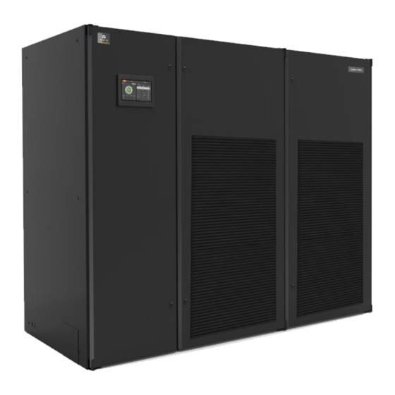
Liebert PEX4 series air conditioning includes 10 models of cooling unit (35 kW, 45 kW, 50 kW, 60 kW, 70 kW, 80 kW, 90 kW, 100 kW 110 kW, 120 kW). These models are available in both upflow and downflow configurations... -
Page 12: Model Description
This chapter introduces models, appearance, components, optional configuration and refrigerant requirements of PEX4. The Liebert PEX4 series precision air conditioner (“PEX4” for short hereafter) is professional equipment, which is a medium-large size precision environment control system, suitable for the equipment room or computer room, featuring high reliability, high sensible heat ratio and large air flow. - Page 13 Digit 17 Main Switch High Voltage Option Main Non-Locking Disconnect Digit 25 Order Identifier Factory Code Dual power automatic Switching (interlock contactor) The standard components are represented in ‘Bold Italic’ font in Table 1-1. Vertiv | Liebert PEX4 | User Manual...
-
Page 14: Components Of Pex4 Model
DC reactor, that supports large torque ± under low speed with small torque ripple and speed control accuracy of 0.5%. It has high thermal reliability, long service life and CE certification. Vertiv | Liebert PEX4 | User Manual... -
Page 15: Oil Return Arrangement
Each circuit only connects to one compressor. • Do not use inferior quality refrigerant. • For any consequences resulting from inferior quality refrigerant, Vertiv does not assume warranty responsibility. Vertiv | Liebert PEX4 | User Manual... -
Page 16: Electronic Expansion Valve (Eev)
Each cooling module consists of two separate evaporators, ‘V’ pattern for upflow unit and ‘A’ pattern for downflow unit. Figure 1-4 Evaporator Coil Vertiv | Liebert PEX4 | User Manual... -
Page 17: Dehumidification- Ec Fan
• Modbus RTU – Modbus Remote Terminal Unit (RTU) communication protocol over a RS-485 serial network (also known as Modbus RTU RS-485) • SNMP (need to choose SIC card which is an optional component) Vertiv | Liebert PEX4 | User Manual... -
Page 18: Additional Features
The infrared humidifier in the Liebert PEX4 series provides quicker and more responsive operation which is quite important for mission-critical applications. These humidifiers reduce the dependency of water quality. -
Page 19: Electrical Heating
Overheat Switches and one manual reset Overheat Switch. No. Description Description Zero line (blue) Live line (red) Temperature controller soleplate Temperature controller soleplate Live line (red) Live line (red) Temperature controller soleplate Figure 1-7 Electrical Heater Vertiv | Liebert PEX4 | User Manual... -
Page 20: Upflow Plenum
The primary purpose of the sensor is to examine the air temperature and to initialize the anti-fire measures installed in the facility. Fire detector trips at 125 F±6 F, and when fire alarm occurs the unit will shutdown. Refer Figure 1-9. Vertiv | Liebert PEX4 | User Manual... -
Page 21: High-Efficiency Filter
Low temperature kit is also used when the outdoor unit is being placed more than 5m below from the indoor unit, consult Vertiv representative for more details. Vertiv | Liebert PEX4 | User Manual... -
Page 22: Operating & Storage Environmental Requirements
Storage time performance of the system needs to be re-calibrated. Consult Vertiv local representative when operating in the following conditions: The voltage of the air conditioning unit is beyond the range of the operating voltage. The altitude is higher than 1000 m. -
Page 23: Chapter 2: Installation
Figure 2-1 Moving an Equipment Using a Forklift Truck Vertiv | Liebert PEX4 | User Manual... -
Page 24: Unpacking
Honey Comb Paper Board. For better understanding see Figure 2-3. No. Description Description Top Cover Honey Comb Paper Board Remove Top Cover Remove sealing plastic film and Honey Comb Paper Board Figure 2-3 Removal of Honey Comb Paper Board Vertiv | Liebert PEX4 | User Manual... - Page 25 The unit is fixed onto the base pallet with M8×65 bolts or M8×90 screw, as shown in Figure 2-6. Use a 17 mm open-end spanner, ratchet spanner or sleeve to remove the fixing bolts. Vertiv | Liebert PEX4 | User Manual...
-
Page 26: Inspection
Check that the fittings are complete and the components are intact against the packing list. If any parts are missing or damage is found, report immediately to the local office of the carrier and Vertiv local representative. 2.2. Installation Preparation (Site Preparation) The PEX4 series is streamlined to keep the data centers, computer rooms and similar ecosystems in a favorable environment. -
Page 27: Installation Space Requirements
• Vertiv recommends that the site preparation is defined as per the requirements. However, if these require- ments are not met, Vertiv recommends that rectifications to be made on the site in order to comply with the specified requirements and conditions. -
Page 28: Maintenance Space Requirement
Air Cooled Series inch Front 35.4” The given space parameters are used to provide regular maintenance, such as changing the air filter, adjusting the supply of the unit, cleaning the humidifier and so on. Vertiv | Liebert PEX4 | User Manual... -
Page 29: Installation Tools
Vertiv | Liebert PEX4 | User Manual... -
Page 30: System Arrangement During Installation
The refrigerant piping is required to connect the indoor and outdoor units of the air-cooled system. The system arrangement diagram of the refrigeration system is shown in Figure 2-8 Figure 2-8 System Arrangement Vertiv | Liebert PEX4 | User Manual... - Page 31 The following points should be considered before checking out the overall layout diagram: • The single system is used as an example. • Components (marked with *) are not supplied by Vertiv but are recommended for the proper circuit operation and maintenance.
-
Page 32: System Installation Mode
The top end of the inverted back-bend should be installed higher than the ultimate level of the copper pipe of the condenser. However, if the condenser is installed lower than the compressor, then there is no need of modification. Vertiv | Liebert PEX4 | User Manual... - Page 33 Figure 2-10, when the condenser is installed at a lower level than the compressor. Vertiv | Liebert PEX4 | User Manual...
-
Page 34: Mechanical Installation
Figure 2-12 Table 2-3 respectively. In PEX4 series unit installation, while lowering the fan, the floor height should not be less than 450 mm. Figure 2-11 Upflow Indoor Unit Figure 2-12 Downflow Indoor Unit Vertiv | Liebert PEX4 | User Manual... -
Page 35: Dimension And Weight Of Condenser
2430x995x1975 95.7”x39.2”x77.8” P2090 2430x995x1975 95.7”x39.2”x77.8” P2100 2430x995x1975 95.7”x39.2”x77.8” P2110 2430x995x1975 95.7”x39.2”x77.8” P2120 2430x995x1975 95.7”x39.2”x77.8” 2.3.2. Dimension and Weight of Condenser Refer to the “LSF/LDF Condenser User Manual” and “LVC Series Condenser User Manual.” Vertiv | Liebert PEX4 | User Manual... -
Page 36: Base Plate Cut-Out Position And Dimension
2-15. Description Description ø Condensate drain outlet Discharge pipe ø Humidification pipe inlet Liquid pipe inlet Cable entry 65x25 Figure 2-13 The Position of Pipe Bottom Outlet of Single Cabinet Unit (unit: mm) Vertiv | Liebert PEX4 | User Manual... - Page 37 Installation Description Description ø Condensate drain outlet Discharge pipe ø Humidification pipe inlet Liquid pipe inlet Cable entry 65x25 Figure 2-14 The Position of Pipe Bottom Outlet of Dual Cabinet Unit (unit: mm) Vertiv | Liebert PEX4 | User Manual...
- Page 38 2-15. Select the inlet and outlet holes according to the actual needs. Ensure only one service is used per opening. The equipment has knock-outs, ensure to mount sleeve to the cable holes to avoid cutting the cables. Vertiv | Liebert PEX4 | User Manual...
-
Page 39: Position And Dimension Of Air Outlet On Top Cover
33.5” 35.4” 35.4” Module series2 33.5” 35.4” 1800 70.9” • Module series 1 contains P1035, P1045, P1050, P1060 series units. • Module series 2 contains P2070, P2080, P2090, P2100, P2110, P2120 series unit. Vertiv | Liebert PEX4 | User Manual... -
Page 40: Indoor Installation
Fixed steel plate customization Expansion bolt mounting hole on-site Upper rubber damping pad customization Expansion bolt mounting hole Incline tie joint (on-site self-determined) height Bottom plate cushion Figure 2-17 Floor Stand of the Single Unit Vertiv | Liebert PEX4 | User Manual... - Page 41 Table 2-5 Dimensions of Rubber Cushion for Vibration Absorbing Specifications Project Units in mm Above Thickness: 3 mm to 5 mm Rubber Damping Side Thickness: 2 mm to 3 mm Bottom Thickness: 10 mm to 12 mm Vertiv | Liebert PEX4 | User Manual...
-
Page 42: Installation Considerations
• Vacuum pumping and refrigerant charging operations, and procedures must conform to the industry standards. • Pressure drop, compressor oil return, noise, and vibration must be considered during the designing and installation process. Vertiv | Liebert PEX4 | User Manual... -
Page 43: Condensate Drain Piping Connection Of The Indoor Unit
2-20. There is a 1/4” copper nut at the end of the copper pipe followed with the 1/4” × 1/2” conversion copper thread connector, which has been connected to the copper nut to avoid any loose contact. Vertiv | Liebert PEX4 | User Manual... - Page 44 Requirements for connecting water inlet pipe of electrode humidifier: Water inlet pipe uses 3/4” G screw- threaded connection pipe. Water filter and water quality detection are recommended to prevent the water quality from affecting the normal operation of the humidifier. Vertiv | Liebert PEX4 | User Manual...
-
Page 45: Refrigerant Piping Connection
Considering the effect of the diameter and wall thickness of copper piping on the pressure drop of the system, the pipe dimensions of the indoor and outdoor units should be determined according to the specifications in Table 2-9 or consult Vertiv local representative. The recommended dimensions of piping is given in Table 2-6 &... -
Page 46: Refrigerant Piping Connection General Principle
• D: Discharge line, L: Liquid pipe. • 25/22: horizontal pipe diameter is 25 mm, vertical pipe diameter is 22 mm • If the pipe length exceeds 60 m or less than 20 m, please consult Vertiv local representative for details. - Page 47 2-10, consult Vertiv local representative. • ‘U’ trap should be provided at every 7.5 m of vertical distance. Please consult Vertiv local representative for details. • Notes and instruction labels are pasted onto the base and the side panel close to the ball valve. Ensure that the ball valve must be wrapped with a wet cloth before brazing to protect the label from burning.
-
Page 48: Refrigerant Requirement
Length of Liquid Pipe (kg/m) 0.17 0.24 0.32 0.42 Please contact Vertiv local representative when operating under the following condition • For non-standard vertical/ horizontal piping length based refrigerant amount. • In case of different condenser. Vertiv | Liebert PEX4 | User Manual... -
Page 49: Copper Pipe Brazing Requirements
2. Nitrogen protection should be used in the brazing process and the edges of the copper pipes should be sealed to prevent impurities and wet air from entering the copper pipe. For specific operation of the seal, refer to Figure 2-22. Vertiv | Liebert PEX4 | User Manual... - Page 50 The soft material also plays a role in the insulation of heat and absorbs vibration between the wall and the surface of the pipe. Vertiv | Liebert PEX4 | User Manual...
-
Page 51: Lowering The Fan
2 PCS) of the L shaped lifting component to ensure that it is fixed properly, and then install the fixing bolts (total 4 PCS) of the winch bracket, as shown in Figure 2-25. Vertiv | Liebert PEX4 | User Manual... - Page 52 2-26, total 4 PCS) for fan lowering. 4. Hold the winch handle firmly, and then turn the handle counterclockwise to lower the fan. After the fan has been lowered, the status is shown in Figure 2-27. Vertiv | Liebert PEX4 | User Manual...
- Page 53 5. Install the fixing bolts, as shown in Figure 2-26 with total 4 PCS of bolts holding the arrangement tight during operation. Description Description Base pallet of unit Bolt Top cover of fan Figure 2-27 Lowered Fan Vertiv | Liebert PEX4 | User Manual...
-
Page 54: Removing Transportation Fixing Plate Of Compressor
• Remove the three L-shaped fixing plates after installation, and then restore the bolts and washers in re- verse sequence of the disassembly process. • The fastening torque of the bolts is (12±1) Nm. Description L-shaped fixed sheet metal (total 3 PCS) Figure 2-28 Position of “L” Shape Fixing Plate Vertiv | Liebert PEX4 | User Manual... -
Page 55: Removing Of Fasteners Of Infrared Humidifier
The electrode humidification bottle has been placed horizontally for transport convenience. At site, the transportation board and fasteners need to be removed and the humidification bottle can be turned into a vertical position, the specific operation steps are as shown in Figure 2-30. Vertiv | Liebert PEX4 | User Manual... - Page 56 Connect the electrode humidifier with drain pipe Removable fixing screw Flip the electrode humidifier as shown Remove transportation fixing screw Connect the inlet of electrode humidifier to the hose pipe line. Figure 2-30 Mounting of Electrode Humidifier Vertiv | Liebert PEX4 | User Manual...
-
Page 57: Removing Pipe Fasteners
The upflow unit must have plenum or have air duct connection, and the fan and heater shall not be accessible after installation. Everything is checked and verified, follow the electrical installation. Vertiv | Liebert PEX4 | User Manual... -
Page 58: Electrical Installation
• Before the wiring, use a volt-meter to measure the power supply voltage and ensure that the power supply has been switched off. • The applicable grid for this air conditioner: TN, TT star connection power system; consult Vertiv local representative for other connections. - Page 59 The types of wiring cables are of copper conductor, and the cross-section-area requirements of the copper wires can vary with the different models. For the cable specification, refer the rated Full Load Ampere (FLA) in Table 2-16. Vertiv | Liebert PEX4 | User Manual...
-
Page 60: Connecting Control Cables
Figure 2-32. The upper part of the terminal optimizing aisle is connected with the unit, and the lower part is the interface of the user control signal line. Vertiv | Liebert PEX4 | User Manual... -
Page 61: Connecting Water-Under-Floor Sensor
2-32, 37# and 38# terminals can connect to remote shutdown switch, and they have been shorted in the factory and the shorting cable must be removed if the terminals are to be connected to the remote shutdown switch. Vertiv | Liebert PEX4 | User Manual... -
Page 62: Customized Alarm Terminal
For specific wiring terminals in the interface board, refer to the circuit diagram printed on the unit label. The controller uses the 24V AC solenoid valve port, if other types of solenoid valves are used, consult Vertiv local representative. Vertiv | Liebert PEX4 | User Manual... -
Page 63: Wiring Of Condenser
The power cables of the outdoor unit are connected to the MCBs reserved in the condenser (refer Figure 2-33). Liebert PEX4 is configured with the indoor unit matching the two systems- the external power supply cables and compressor signal cables respectively. Vertiv | Liebert PEX4 | User Manual... - Page 64 Waterproof joint of compressor signal Waterproof joint of fan power wire Waterproof joint of spray module cable Waterproof joint of fan over temperature switch Figure 2-33 External Power Supply Wiring Diagram Liebert LVC System Vertiv | Liebert PEX4 | User Manual...
-
Page 65: Electrical Installation Inspection
Power cables and ground cables to the MCBs, indoor unit and outdoor unit are well connected. The ratings of the MCBs and fuses are correct. The control cables are well connected. All the cables connections are fastened, with no loose screws. Vertiv | Liebert PEX4 | User Manual... -
Page 66: Chapter 3: Controller Operating Instruction
4. Expert fault diagnosis system, can automatically display the current fault content, helps maintenance personnel for equipment maintenance. 5. It can display 500 historical alarms. 6. Configured CAN interface, using CAN communication protocols. Figure 3-1 HMI Screen Display Panel Main Interface Vertiv | Liebert PEX4 | User Manual... -
Page 67: Light Indicator
The display fails to communicate with the Control Panel or the system shuts down. Green System operating normally. The system has alarms and buzzer rings. 3.3. Start-Up Interface After the unit is powered ON, color display startup screen shown in Figure 3-2. Figure 3-2 Start Interface Vertiv | Liebert PEX4 | User Manual... -
Page 68: User Menu
Status display Displays the current state of the unit and respective components. Displays the current operating status of each sensor and its respective Sensor reading list components. Alarm List Displays all the current alarms. Vertiv | Liebert PEX4 | User Manual... - Page 69 Controller Operating Instruction Figure 3-3 Color Display Screen – Locked Figure 3-4 Color Display Screen – Unlocked Vertiv | Liebert PEX4 | User Manual...
-
Page 70: Password Interface
Figure 3-5 Real-time Sensor Data Parameter List - Unlocked 3.4.1. Password Interface Press on the Lock icon in the upper right corner of the display, the password interface is displayed, as shown in Figure 3-6. Figure 3-6 Password Interface Vertiv | Liebert PEX4 | User Manual... - Page 71 1. Press the Unlock button to enter the password interface. 2. Enter the user correct login password in the password interface. 3. After entering the correct password, in the main interface, the corresponding parameters of the unit can be modified. Vertiv | Liebert PEX4 | User Manual...
-
Page 72: Menu
The latest Alarm SN is the largest number. Press the Up or Down button to scroll through the status records if more than one alarm is activated. Up to 500 historical alarm records can be stored. They will not be cleared upon system Power-OFF. Vertiv | Liebert PEX4 | User Manual... - Page 73 Press the Up or Down button to scroll through the status records if more than one alarm is activated. Up to 500 historical alarm records can be stored. They will not be cleared upon system Power-Off. Vertiv | Liebert PEX4 | User Manual...
- Page 74 3. In the Humidity Setting interface, press to set the corresponding setting value. 4. After the parameters are selected, press Enter to confirm the parameters take effect. 5. Press the Home icon to return to the home page. Vertiv | Liebert PEX4 | User Manual...
- Page 75 1. Control Mode item, Press the drop-down button next to the box. 2. Select the appropriate control mode in the drop-down menu as shown in Figure 3-12 to complete the set. Figure 3-12 Control Mode Settings Vertiv | Liebert PEX4 | User Manual...
- Page 76 3-13. A keyboard appears in the interface. Enter the upper and lower limits, the alarm value will be saved. Figure 3-13 Alarm Setting Parameters Humidifier Setting Parameters: Press the Humidifier Setting icon to enter the humidifier settings page as shown in Figure 3-14. Vertiv | Liebert PEX4 | User Manual...
- Page 77 Teamwork Settings: Press the Parameter Setting in the menu to enter the parameter settings page. Press the Teamwork Setting to modify the teamwork function, set the parameters such as the Rotation Cycle, Rotation Quantity and Rotate At (the rotation time), as shown in Figure 3-15. Figure 3-15 Teamwork Settings Vertiv | Liebert PEX4 | User Manual...
- Page 78 Display Language setting to press the language settings in the drop- down box, display English support. The drop- down box of the unit type can be set on the unit type. Figure 3-17 Display Settings Vertiv | Liebert PEX4 | User Manual...
-
Page 79: Unit Status
Figure 3-18 Start Password Settings 3.5. Unit Status 3.5.1. Temperature and Humidity Status Figure 3-19 Temperature and Humidity Status Vertiv | Liebert PEX4 | User Manual... - Page 80 “-” can reduce the display range of the graph, press reduced to two hours.“+” can enlarge the graph display range, press to enlarge two hours. Figure 3-20 Temperature Curves Figure 3-21 Humidity Curves Vertiv | Liebert PEX4 | User Manual...
-
Page 81: Power Information Display
Controller Operating Instruction 3.5.2. Power Information Display Figure 3-22 Power Information Display 3.6. Hardware and Software Information Figure 3-23 Hardware & Software Information Vertiv | Liebert PEX4 | User Manual... -
Page 82: Remote Monitoring Mode
• Modbus RTU – Modbus Remote Terminal Unit (RTU) communication protocol over a RS-485 serial network (also known as Modbus RTU RS-485) • Optional SIC cards, access through SNMP network management software agreement. Vertiv | Liebert PEX4 | User Manual... -
Page 83: Chapter 4: General Maintenance
6. Check that the sockets and plugs are in good condition. Replace those loosen ones. 7. If the power cables are damaged, to avoid any further damage, the cables must be replaced by professional personnel. Vertiv | Liebert PEX4 | User Manual... -
Page 84: Control Component Appearance Inspection
• Simulate and check the operation of the protection devices including high and low pressure alarm, high and low temperature alarm, high water level alarm and over-temperature protection. • Check the water detection sensor. Vertiv | Liebert PEX4 | User Manual... -
Page 85: Water Leak Detector
The filter must be checked once a month, and be replaced as required during operation. • Cut the power supply before replacing the filter. • Clear the fan running time to ‘0’ after replacing the filter. Vertiv | Liebert PEX4 | User Manual... -
Page 86: Fan Kit Maintenance
Before exercising the corresponding operation, ensure that the power supply has been switched off; also, ensure that the water in the water pan is close to the room temperature before draining the water from the infrared humidifier water pan to avoid the personal injury. Vertiv | Liebert PEX4 | User Manual... -
Page 87: Electrical Heater
3. If the cable is not functioning properly, remove the electrical heater and check if the manual reset switch is disconnected. Next, check the automatic reset switches or the electric heater pipe for damage or faulty condition. Before exercising the corresponding operation, ensure that the power supply has been switched off. Vertiv | Liebert PEX4 | User Manual... -
Page 88: Cooling System
3. Inlet and outlet water pipes must be properly fixed and must not vibrate against the wall, floor or frame of the unit. 4. Inspect all water pipes and fixing brackets every six months for signs of wear and tear. Vertiv | Liebert PEX4 | User Manual... -
Page 89: Chapter 5: Troubleshooting
• If the motor is over heated, power-off the fan, and power-on after the motor cools down. • If there is other failure mode, then it should be sent to manufacture for maintenance. Vertiv | Liebert PEX4 | User Manual... -
Page 90: Heating System Troubleshooting
• Check if the wiring of switch is connected to controller. compressor is High pressure switch • Check if there is high pressure alarm on high pressure switch not running actuates status. Vertiv | Liebert PEX4 | User Manual... - Page 91 5 and the actual pressure are within ± 0.3 bar (high and low pressure abnormality minutes sensor values can be read in service tool, referred in gauge pressure). Vertiv | Liebert PEX4 | User Manual...
- Page 92 The compressor • If it runs reversely, replace any two compressor L line suction and running reversely (inverter output). discharge • If another reason, then replace the compressor. pressure Suction and discharge unchanged connected Vertiv | Liebert PEX4 | User Manual...
- Page 93 Suction superheat is Adjust the Electronic Expansion Valve settings or add the appropriate overheating high amount of refrigerant. Remarks: The basis of above symptoms are based on the existing CFC. Vertiv | Liebert PEX4 | User Manual...
-
Page 94: Infrared Humidifier Troubleshooting
The manual-reset high-temp switch is fitted above the lamps. When overheat occurs due to abnormal situation, the switch cut-offs the power supply to the lamps. Description Reset button Figure 5-1 Infrared Humidifier Reset Button Vertiv | Liebert PEX4 | User Manual... - Page 95 © 2019 Vertiv Group Corp. All rights reserved. Vertiv™ and the Vertiv logo are trademarks or registered marks of Vertiv Group Corp. All other names and logos referred to are trade names, trademarks, or registered trademarks of their respective owners. While every precaution has been taken to ensure accuracy and completeness herein.
Need help?
Do you have a question about the Liebert PEX4 Series and is the answer not in the manual?
Questions and answers