Advertisement
DPY351
Monitor and Control Panel for ADELBus Network devices
Instruction Manual
Thank you for having chosen one of our products for your work.
We are certain that it will give the utmost satisfaction and be a notable
help on your job and application.
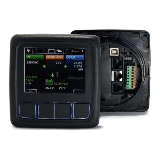
Product Description
The DPY351 is a robust and versatile multifunction display that allows
monitoring, configuring and managing ADELSystem connected devices
in an ADELBus network. It is equipped with a high-brightness and wide
viewing-angle 3.5'' TFT screen which guarantees an optimum visibility in
any operating condition. The user interface is clear, intuitive and allows
configuring and managing the ADELBus network through its Ethernet
interface by remotely monitoring the connected devices, using the
SNMP, Modbus TCP and MQTTs protocols. The configuration of the
Ethernet connection is very straightforward and can be done by means
of the embedded webserver or the intuitive user interface. The device IP
addressing can be static or dynamic using the DHCP protocol. This
makes the connection of a DPY351 to a LAN very easy. It is possible to
connect several devices in chain together, up to 32.
Table of Contents
Product Description .............................................................................. 1
1
Safety and warning notes .................................................... 2
2
How to Install ........................................................................ 2
2.1
Dimensions ............................................................................. 2
2.2
Panel Mounting....................................................................... 2
2.3
How to Supply DPY351 .......................................................... 2
2.4
Device Connection (Fig.2) ...................................................... 2
2.4.1
Auxiliary temperature sensor (AUX1) ............................... 2
2.4.2
Ethernet Connection (AUX2) ............................................ 2
2.4.3
PowerBus Connection (AUX3) ......................................... 2
2.4.4
USB Connection (AUX4) .................................................. 2
2.4.5
Auxiliary Input Power (AUX5) ........................................... 2
2.4.6
Input / Output State Terminal 3,4,7,8 (AUX5) .................. 2
2.4.7
How to connect the shunt in CBI Size 3 ........................... 2
2.4.8
Cabel Connections (AUX5) .............................................. 2
2.5
Power On Configuration ......................................................... 3
2.5.1
Automatic Power On Display (AUX6) ............................... 3
2.6
Hardware configurations RS485 and CAN bus ..................... 3
2.6.1
RS 485 Terminations (AUX6) ........................................... 3
2.6.2
Can Terminations (AUX6) ................................................ 3
2.7
Keyboard ................................................................................ 3
3
ADELBus Connections ........................................................ 3
3.1
Event based commands ......................................................... 3
3.2
How to set up an ADELBus network ...................................... 3
3.3
How to set an ADELBus network with more than one DPY351
(Modbus View Mode) .......................................................................... 3
4
Ethernet Configuration ........................................................ 3
4.1.1
Connect HTTP server for the first time ............................. 3
4.1.2
Customizing the ethernet interface and services ............. 3
4.1.3
Saving / resetting the customized ethernet parameters ... 4
5
Features for Managing ......................................................... 4
5.1
Monitoring ............................................................................... 4
Via Luigi Barchi 9/B – Reggio Emilia 42124 – Italy
Phone : +39 0522 345518 –
5.1.1
Display Configuration"Welcomepage" .............................. 4
5.1.2
Display Configuration "Network menu" ............................. 4
5.2
Configuration .......................................................................... 4
5.3
Daisy Chain ............................................................................ 4
5.4
Alarms management............................................................... 4
5.5
History ..................................................................................... 4
5.6
Event ....................................................................................... 4
6
Technical Data ...................................................................... 4
6.1
Input Data ............................................................................... 4
6.2
User Interface ......................................................................... 4
6.2.1
Display Screen .................................................................. 4
6.2.2
Controls ............................................................................. 4
6.3
Data Connection ..................................................................... 4
6.3.1
Modbus Communication RS485 ....................................... 4
6.3.2
CAN Communication ........................................................ 5
6.4
Ambient Conditions................................................................. 5
6.5
General Data .......................................................................... 5
6.6
Accessory ............................................................................... 5
6.7
Hardware Port ......................................................................... 5
6.7.1
Digital Input ports "Aux5" .................................................. 5
6.7.2
Analog Input ports "Aux5" ................................................. 5
6.7.3
Output port "Aux5" ............................................................ 5
6.8
Software Port .......................................................................... 5
6.8.1
Remote Monitoring "Ethernet Connection" ....................... 5
6.8.2
Web Server ....................................................................... 5
6.9
Norms and certifications ......................................................... 5
6.9.1
Immunity and Emission ..................................................... 5
6.10
Electrical Safety for mounting ................................................. 5
6.10.1
Environmental Norm Conditions ................................. 5
7.1
Annex 1: Mounting template: .................................................. 5
www.adelsystem.com
Advertisement
Table of Contents

Related Manuals for ADELSYSTEM DPY351


Summary of Contents for ADELSYSTEM DPY351
- Page 1 DHCP protocol. This Configuration ................4 makes the connection of a DPY351 to a LAN very easy. It is possible to Daisy Chain ................4 connect several devices in chain together, up to 32.
-
Page 2: Safety And Warning Notes
3mm flat blade screw driver to push in the Spring Connect to supply unless power has been switched off or the area is known to be non- the DPY351 from a CBI Size3, it is necessary to connect the Output Load + and hazardous. -
Page 3: Ethernet Configuration
ADELBus network, then N-1 displays shall be configured in View Mode. SNMP v2c In this case only one DPY351 is a master and it polls the devices, the other The DPY351 can act as a gateway between an ADELsystem power device DPY351s receive the data from the Bus and they take the information into (such as the CBI Size 3 and 4) and a SNMP manager. -
Page 4: Technical Data
Video: https://youtu.be/BzRc8YJ8F4Q Configuration With the DPY351, it is possible to modify the parameters of any ADELSystem device connected: DC-Ups, Power Supply and Battery Charger. In term of: Battery Performance Load Performance Device Configurations Advanced Configuration: Primary PW:1234 ... - Page 5 6.3.2 CAN Communication 6.7.2 Analog Input ports “Aux5” Aux3: RJ45 Input: N° 1 Supported Protocols J1939 Application Pin Pins 5,6 Raw CAN For Shunt connection 50 A Can Open 6.7.3 Output port “Aux5” Supported Baud Rate 50 Kbit/s, 100 Kbit/s, 125 Output N°...
Need help?
Do you have a question about the DPY351 and is the answer not in the manual?
Questions and answers