
Related Manuals for Piper SENECA II


Summary of Contents for Piper SENECA II
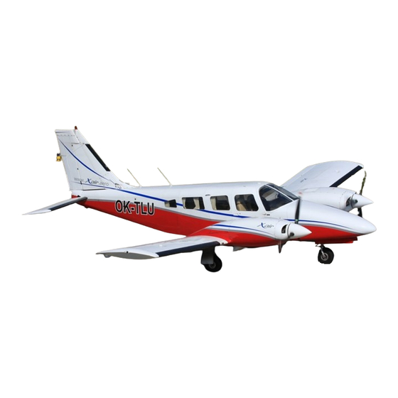
- Page 1 SERVICE MANUAL PA - 34 - 200T PIPER AIRCRAFT CORPORATION PART NUMBER 761-590 OCTOBER 31, 2019...
- Page 2 Published by Piper Aircraft, Inc. Attn: Technical Publications 2926 Piper Drive Vero Beach, Florida 32960 U.S.A. © 1974, 1979-1983, 1986-1987, 1996-1997, 2007, 2009, 2019 Piper Aircraft, Inc. Member General Aviation Manufacturers Association...
- Page 3 PIPER SENECA II SERVICE MANUAL REVISION STATUS Definitions A. Revision The data in the revision column is comprised of two elements: (1) A Type of Revision Code: ORG = Original, CR = Complete Revision, and PR = Partial Revision. NOTE: Partial Revisions (PR) are listed only until the next Complete Revision (CR) is published.
- Page 4 3. Availability This service manual, related inspection reports and manuals, service publications (SB, SL, etc.) and other Piper publications are available as described in the Owner Publications Catalog (part of the Customer Service Information File, see below). Consult the “Customer Service Information File” (a free download from the Piper Aircraft, Inc. website http://www.piper.com/technical-publications-documents/...
-
Page 5: Table Of Contents
PIPER Publications ........ - Page 6 PIPER SENECA II SERVICE MANUAL THIS PAGE INTENTIONALLY BLANK INTRODUCTION - TABLE OF CONTENTS 01/01/09...
-
Page 7: Instructions For Continued Airworthiness
Genuine PIPER parts are produced and inspected under rigorous procedures to insure airworthiness and suitability for use in PIPER airplane applications. Parts purchased from sources other than PIPER, even though identical in appearance, may not have had the required tests and inspections performed, may be different in fabrication techniques and materials, and may be dangerous when installed in an airplane. - Page 8 Genuine PIPER parts are produced and inspected under rigorous procedures to insure airworthiness and suitability for use in PIPER airplane applications. Parts purchased from sources other than PIPER, even though identical in appearance, may not have had the required tests and inspections performed, may be different in fabrication techniques and materials, and may be dangerous when installed in an airplane.
-
Page 9: Serial Number Explanation
PIPER SENECA II SERVICE MANUAL Effectivity This service manual is effective for the PA-34-200T Seneca II airplane serial numbers 34-7570001 thru 34-8170092. This encompasses the following model years: NOTE: The following is provided as a general reference only. Model Sub-Model... - Page 10 PIPER SENECA II SERVICE MANUAL Effectivity This service manual is effective for the PA-34-200T Seneca II airplane serial numbers 34-7570001 thru 34-8170092. This encompasses the following model years: NOTE: The following is provided as a general reference only. Model Sub-Model...
- Page 11 PIPER SENECA II SERVICE MANUAL Effectivity This service manual is effective for the PA-34-200T Seneca II airplane serial numbers 34-7570001 thru 34-8170092. This encompasses the following model years: NOTE: The following is provided as a general reference only. Model Sub-Model...
-
Page 12: Identifying Revised Material
PIPER SENECA II SERVICE MANUAL Deviations from the legacy Aerofiche grid numbering system will occur when it becomes necessary to add pages to the manual and will typically take two forms: A. Inserting pages between two existing grids in the same row. -
Page 13: Warnings, Cautions And Notes
11. Accident/Incident Reporting To improve our Service and Reliability system and aid in Piper’s compliance with FAR 21.3, knowledge of all incidents and/or accidents must be reported to Piper immediately. To expedite and assist in reporting all incidents and accidents, Piper Form 420-01 has been created. See Service Letter 1041 for latest revision. - Page 14 PIPER SENECA II SERVICE MANUAL (3) ALTERNATOR: Vendor: Kelly Aerospace Power Systems (888) 461-6077 Airport Complex FAX: (334) 227-8596 P. O. Box 273 Fort Deposit, Alabama 36032 http://www.kellyaerospace.com/index.html Overhaul Manual: OE-A2 Overhaul Manual (Starters and Alternators) (4) AUTOFLIGHT: Vendor: Honeywell One Technology Center 23500 W.
- Page 15 PIPER SENECA II SERVICE MANUAL (9) ENGINE: Vendor: Teledyne Continental Motors (800) 718-3411 Attn: Aircraft Products Division FAX: (251) 432-7352 Mobile, Alabama 36601 Operators Handbook = Form No. X-30583 Overhaul Manual = Form No. X-30596A Parts Catalog = Form No. X-30597A...
- Page 16 PIPER SENECA II SERVICE MANUAL (15) LIGHTS - NAVIGATION, STROBE, AND STANDBY/MAP LIGHTS: Vendor: Whelen Engineering Co. Inc. (860) 526-9504 Route 145, Winthrop Rd. FAX: (860) 526-2009 Chester, Connecticut 06412 http://www.whelen.com/ (16) MAGNETOS: Vendor: TCM Aircraft Products (800) 718-3411 P.O. Box 90...
- Page 17 PIPER SENECA II SERVICE MANUAL (19) PROPELLER: Vendor: Hartzell Propeller Inc. (937) 778-4379 One Propeller Place FAX: (937) 778-4321 Piqua, OH 45356-2634 http://www.hartzellprop.com/index2.htm Owner’s Manual: Manual No. 115N Overhaul Instructions: Manual No. 117D Vendor: McCauley Propeller Systems P.O. Box 7704 Wichita, KS 67277-7704 http://www.mccauley.textron.com/home.html...
-
Page 18: Section Index Guide
PIPER SENECA II SERVICE MANUAL 13. Section Index Guide SECTION TITLE GRID NO. INTRODUCTION AIRWORTHINESS LIMITATIONS 1A13 HANDLING AND SERVICING 1A16C INSPECTION 1C31 STRUCTURES 1D11 SURFACE CONTROLS 1F20A HYDRAULIC SYSTEM LANDING GEAR AND BRAKES 1J4C VIII POWERPLANT FUEL SYSTEM 2D2A... - Page 19 PIPER SENECA II SERVICE MANUAL THIS PAGE INTENTIONALLY BLANK SECTION INDEX GUIDE 01/01/09 1A12D...
-
Page 20: List Of Illustrations
PIPER SENECA II SERVICE MANUAL LIST OF ILLUSTRATIONS Figure Grid No. 2-1. Three View .......... - Page 21 PIPER SENECA II SERVICE MANUAL LIST OF ILLUSTRATIONS (cont) Figure Grid No. 4-8a. Metal Wire Stitching Repair ....... . .
- Page 22 PIPER SENECA II SERVICE MANUAL LIST OF ILLUSTRATIONS (cont) Figure Grid No. 6-8. End Gland Locking Device ....... . .
- Page 23 PIPER SENECA II SERVICE MANUAL LIST OF ILLUSTRATIONS (cont) Figure Grid No. 8-12. Flyweight Clearance of Impulse Coupling ..... 2B13 8-13.
- Page 24 PIPER SENECA II SERVICE MANUAL LIST OF ILLUSTRATIONS (cont) Figure Grid No. 11-4. Testing Rotor for Ground ........
- Page 25 PIPER SENECA II SERVICE MANUAL LIST OF ILLUSTRATIONS (cont) Figure Grid No. 13-16. Suggested Design for Seal Plates, Plugs, and Caps for Combustion Tube Leakage Test ......
- Page 26 PIPER SENECA II SERVICE MANUAL LIST OF ILLUSTRATIONS (cont.) Figure Grid No. 14-24. Air Conditioning System Installation ......
- Page 27 PIPER SENECA II SERVICE MANUAL THIS PAGE INTENTIONALLY BLANK LIST OF ILLUSTRATIONS 01/01/09 1A12L...
- Page 28 PIPER SENECA II SERVICE MANUAL LIST OF TABLES Table Grid No. II-I. Leading Particulars and Principal Dimensions ....1A22 II-II. Thread Lubricants ........
- Page 29 PIPER SENECA II SERVICE MANUAL LIST OF TABLES (cont) Table Grid No. X-III. Gyro Horizon Indicator ........
- Page 30 PIPER SENECA II SERVICE MANUAL THIS PAGE INTENTIONALLY BLANK 01/01/09 LIST OF TABLES 1A12O...
- Page 31 PIPER SENECA II SERVICE MANUAL END OF SECTION LIST OF TABLES 01/01/09 1A12P...
- Page 32 PIPER SENECA II SERVICE MANUAL SECTION AIRWORTHINESS LIMITATIONS 1A13...
- Page 33 PIPER SENECA II SERVICE MANUAL THIS PAGE INTENTIONALLY BLANK 1A14...
- Page 34 PIPER SENECA II SERVICE MANUAL SECTION I - AIRWORTHINESS LIMITATIONS TABLE OF CONTENTS Paragraph Grid No. Limitations ..........
- Page 35 PIPER SENECA II SERVICE MANUAL THIS PAGE INTENTIONALLY BLANK I - TABLE OF CONTENTS 01/01/09 1A16...
- Page 36 43.10 in a manner that does not affect part structural integrity, i.e. - no surface deformation such as vibration/etching allowed. B. Parts that have accumulated the life limit shall be disposed of in accordance with the applicable FARs. Piper recommends life limited parts with no time and/or cycles remaining be completely destroyed. 01/01/09...
- Page 37 PIPER SENECA II SERVICE MANUAL END OF SECTION I - AIRWORTHINESS LIMITATIONS 01/01/09 1A16B...
- Page 38 PIPER SENECA II SERVICE MANUAL SECTION HANDLING SERVICING 1A16C...
- Page 39 PIPER SENECA II SERVICE MANUAL THIS PAGE INTENTIONALLY BLANK 1A16D...
- Page 40 PIPER SENECA II SERVICE MANUAL SECTION II - HANDLING AND SERVICING TABLE OF CONTENTS Paragraph Grid No. 2-1. Introduction ..........
- Page 41 PIPER SENECA II SERVICE MANUAL SECTION II - HANDLING AND SERVICING TABLE OF CONTENTS (continued) Paragraph Grid No. 2-39. Tires ...........
- Page 42 PIPER SENECA II SERVICE MANUAL SECTION II HANDLING AND SERVICING 2-1. INTRODUCTION. This section contains routine handling and servicing procedures that are most frequently encountered. Frequent reference to this section will aid the individual by providing information such as the location of various components, ground handling procedures, routine service procedures and lubrication.
- Page 43 PIPER SENECA II SERVICE MANUAL Figure 2-1. Three View II - HANDLING AND SERVICING 01/01/09 1A20...
- Page 44 PIPER SENECA II SERVICE MANUAL Figure 2-2. Station References 01/01/09 II - HANDLING AND SERVICING 1A21...
- Page 45 PIPER SENECA II SERVICE MANUAL TABLE II-I. LEADING PARTICULARS AND PRINCIPAL DIMENSIONS MODEL PA-34-200T SENECA II ENGINE Manufacturer Continental Model - Left TSIO-360E-1A (CW) or TSIO-360-EB Model - Right LTSIO-360E-1A (CCW) or LTSIO-360-EB FAA Type Certificate E9CE Rated Horsepower (Max. Continuous, Sea Level)
- Page 46 PIPER SENECA II SERVICE MANUAL TABLE II-I. LEADING PARTICULARS AND PRINCIPAL DIMENSIONS (cont) PROPELLER Manufacturer Hartzell McCauley (11) (12) Hub, Model: Left Engine BHC-C2YF-2CKF 3AF34C502 Right Engine BHC-C2YF-2CLKF 3AF34C503 Alternate Hub, Models: BHC-C2YF-2CKUF (Left Eng.) BHC-C2YF-2CLKUF (Right Eng.) Blade, Model: Left Engine FC8459-8R &...
- Page 47 CABLE TENSIONS Refer to Section V (6) PA-34-200T MODEL WITH HEAVY DUTY BRAKES, WHEELS AND EITHER B.F. GOODRICH NYLON-T.T. TYPE III TIRES OR McCREARY AIR HAWK TYPE III. (REFER TO PIPER KIT NO. 761 048V.) II - HANDLING AND SERVICING 01/01/09...
- Page 48 PIPER SENECA II SERVICE MANUAL 2-7a. THREADED FASTENER INSTALLATION. (PIR-PPS20015-1, Rev. U.) Fastener Lengths Fastener lengths must be long enough to prevent bearing loads on threads. The complete chamfer or end radius of the fastener or screw must extend through the nut.
- Page 49 PIPER SENECA II SERVICE MANUAL TABLE II-II. THREAD LUBRICANTS Line Lubricant WARNING: DO NOT PERMIT SAE-AMS-2518 ANTI-SEIZE COMPOUND TO ENTER SYSTEM. APPLY TO FITTING THREADS ONLY. Air Conditioning Refrigerant SAE-AMS-2518, Anti-Seize Compound, Graphite Petrolatum Brakes MIL-PRF-5606, Hydraulic Fluid Fuel SAE-AMS-2518, Anti-Seize Compound, Graphite Petrolatum...
- Page 50 PIPER SENECA II SERVICE MANUAL 2-8. TORQUE REQUIREMENTS. CAUTION: DO NOT OVERTORQUE FITTINGS. Table II-III lists the torque values for flared fittings of various sizes and material. NOTE: When installing flared fittings, verify that male threads are properly lubricated. The torque values given in Table II-IV are derived from oil-free cadmium-plated threads and are recommended for all airframe installation procedures where torquing is required, unless other values are specified in subject chapter/section.
- Page 51 PIPER SENECA II SERVICE MANUAL The friction drag torque can be determined as follows: Run the nut down to near contact (but not in contact) with the bearing surface and check the "friction drag torque" required to turn the nut.
- Page 52 3/8-24 (190 x .10) + (270-190) = 19 + 80 = 99 in.-lbs. Accomplish this for all fasteners common to the gapped interface. If no gap exists after accomplishing the above, finish torquing to final torque. If a gap remains consult your Piper Dealer’s Service Advisor (DSA) for further assistance.
- Page 53 PIPER SENECA II SERVICE MANUAL THIS PAGE INTENTIONALLY BLANK II - HANDLING AND SERVICING 01/01/09 1A30...
- Page 54 PIPER SENECA II SERVICE MANUAL 2-8a. TORQUE WRENCHES. Torque wrenches should be checked daily and calibrated by means of weights and a measured lever arm to make sure that inaccuracies are not present. Checking one torque wrench against another is not sufficient and is not recommended.
- Page 55 PIPER SENECA II SERVICE MANUAL TABLE II-IV. RECOMMENDED NUT TORQUES (Sheet 1 of 2) Bolts - Steel Bolts - Aluminum AN 3 thru AN 20 MS 20004 AN 3DD Series AN 42 thru AN 49 NAS 333 thru NAS 340...
- Page 56 PIPER SENECA II SERVICE MANUAL TABLE II-IV. RECOMMENDED NUT TORQUES (Sheet 2 of 2) Bolts - Steel Bolts - Aluminum AN 3 thru AN 20 MS 20004 AN 3DD Series AN 42 thru AN 49 NAS 333 thru NAS 340...
- Page 57 PIPER SENECA II SERVICE MANUAL Figure 2-3. Access Plates and Panels II - HANDLING AND SERVICING 01/01/09...
- Page 58 PIPER SENECA II SERVICE MANUAL Figure 2-3. Access Plates and Panels (cont.) 01/01/09 II - HANDLING AND SERVICING...
- Page 59 PIPER SENECA II SERVICE MANUAL THIS PAGE INTENTIONALLY BLANK II - HANDLING AND SERVICING 01/01/09...
- Page 60 PIPER SENECA II SERVICE MANUAL Figure 2-4. Jacking 2-9. STEP, HANDHOLD AND WALKWAYS. CAUTION: WALK ON THE WALKWAYS ONLY TO AVOID DAMAGE TO THE WINGS. A fixed handhold is located on the right side of the fuselage, above and aft of the second window. The walkway is made up of a non-skid material which is in turn, bonded to the wing surface.
- Page 61 PIPER SENECA II SERVICE MANUAL Figure 2-5. Weighing 2-13. WEIGHING. (Refer to Figure 2-5.) The airplane may be weighed by the following procedure: Position a scale and ramp in front of each of the three wheels. Secure the scales from rolling forward and tow the airplane up onto the scales. (Refer to Towing, Paragraph 2-18.)
- Page 68 PIPER SENECA II SERVICE MANUAL CAUTION: DIRT AND FOREIGN PARTICLES FORM AROUND THE FILLER PLUGS OF THE LANDING GEAR STRUTS, THEREFORE, BEFORE ATTEMPTING TO REMOVE THESE PLUGS, THE AREA AROUND THE FILLER PLUGS SHOULD BE CLEANED WITH COMPRESSED AIR AND/OR WITH A QUICK DRYING SOLVENT.
- Page 70 PIPER SENECA II SERVICE MANUAL 2-36. FILLING MAIN GEAR OLEO STRUTS. To fill the main gear oleo struts with hydraulic fluid (MIL-H-5606) one of the following methods should be used, depending on the type of service performed on the strut assembly: Method I: Addition of small amount of fluid.
- Page 71 PIPER SENECA II SERVICE MANUAL THIS PAGE INTENTIONALLY BLANK II - HANDLING AND SERVICING 01/01/09 1B18...
- Page 72 PIPER SENECA II SERVICE MANUAL 2-37. INFLATING OLEO STRUTS. After making certain that an oleo strut has sufficient fluid, attach a strut pump to the air valve. With the airplane at empty weight (full fuel and oil only) fill the main strut to 250 psi and the nose gear to 150 psi.
- Page 73 PIPER SENECA II SERVICE MANUAL 2-39. TIRES. 2-40. SERVICING TIRES. The tires should be maintained at the pressure specified in Table II-I. When checking tire pressure, examine the tires for wear, cuts, bruises and slippage. The tire, tube, and wheel should be balanced when installed.
- Page 74 PIPER SENECA II SERVICE MANUAL Figure 2-8a. Tire Balancer When balance is attained, put a chalk mark on the sidewall directly below the patch. Use one mark for each half ounce of weight needed. Mark the valve stem location on the tire and the opposite wheel half to assure reassembly in the same position.
- Page 75 PIPER SENECA II SERVICE MANUAL 2-43. SERVICING HYDRAULIC PUMP/RESERVOIR. The fluid level of the reservoir of the combination pump and reservoir should be checked every 50 hours by viewing the fluid through the filler plug hole in the hydraulic pump. Access to the pump is through the panel at the right forward side of the nose baggage compartment.
- Page 76 PIPER SENECA II SERVICE MANUAL 2-48. CLEANING LANDING GEAR. Struts and Torque Links Before cleaning the landing gear struts and torque links, place a plastic cover or similar material over the wheel and brake assembly. Place a pan under the gear to catch waste.
- Page 77 PIPER SENECA II SERVICE MANUAL After cleaning plastic surfaces, apply a thin coat of hard polishing wax. Rub lightly with a soft cloth. Do not use a circular motion. A severe scratch or mar in plastic can be removed by using jeweler’s rouge to rub out the scratch.
- Page 78 PIPER SENECA II SERVICE MANUAL 2-58. OIL SCREEN (SUCTION). The oil suction screen is located on the bottom aft end of the engine sump, installed horizontally. To remove, cut the safety wire and remove the hex head plug. The screen should be cleaned at each oil change to remove any accumulation of sludge and to examine for metal filings or chips.
- Page 79 PIPER SENECA II SERVICE MANUAL 2-61. LUBRICATION INSTRUCTIONS. Proper lubrication procedures are valuable both as a means of prolonging the service life of the airplane and reducing the frequency of repairs. The periodic application of recommended lubricants to their relevant bearing surfaces, together with cleanliness, ensures the maximum efficiency and utmost service life of all moving parts.
- Page 80 PIPER SENECA II SERVICE MANUAL 2-64. LUBRICATION CHARTS. (PIR-37110D.) The lubrication charts consist of individual illustrations for the various aircraft systems. Each component to be lubricated is indicated by a number, the type of lubricant and the frequency of application. Special instructions are listed in Table II-VI before the lubrication charts.
- Page 81 PIPER SENECA II SERVICE MANUAL TABLE II-V. LUBRICANT SPECIFICATION CROSS-REFERENCE (Sheet 1 of 2) Old Spec / Product superceded by New Spec / Product Product Type MIL-C-16173 MIL-PRF-16173E Corrosion Preventative Compound, Solvent Cutback, Cold Application. MIL-G-3278 MIL-PRF-23827C Grease, Aircraft & Instrument, Gear and Actuator Screw.
- Page 82 PIPER SENECA II SERVICE MANUAL TABLE II-V. LUBRICANT SPECIFICATION CROSS-REFERENCE (Sheet 2 of 2) Old Spec / Product superceded by New Spec / Product Product Type MIL-T-5544 SAE-AMS-2518 Thread Compound, Anti-Seize, Graphite-Petrolatum MIL-T-27730 A-A-58092 Tape, Anti-Seize, Polytetrafluoroethylene MS-122 * MS-122AD *...
- Page 83 PIPER SENECA II SERVICE MANUAL TABLE II-VI. SPECIAL INSTRUCTIONS 1. BEARINGS AND BUSHINGS - Clean exterior with a quick-drying solvent before lubricating. 2. LUBRICATION POINTS - Wipe all lubrication points clean of old grease, oil, dirt, etc., before lubricating. 3. WHEEL BEARINGS - Disassemble and clean with a quick-drying solvent. Ascertain that grease is packed between the roller and cone.
- Page 84 PIPER SENECA II SERVICE MANUAL COMPONENT LUBRICANT FREQUENCY 1. MAIN GEAR PIVOT POINTS (See Spec. Instr. 1) MIL-PRF-23827 100 HRS 2. MAIN GEAR DOOR HINGE (See Spec. Instr. 2) MIL-PRF-7870 100 HRS 3. MAIN GEAR TORQUE LINKS (See Spec. Instr. 1)
- Page 85 PIPER SENECA II SERVICE MANUAL COMPONENT LUBRICANT FREQUENCY 1. NOSE GEAR STRUT HOUSING (See Spec. Instr. 1 and 2) MIL-PRF-23827 100 HRS 2. NOSE GEAR PIVOT POINT AND HYDRAULIC CYLINDER ROD END (See Spec. Instr. 2) MIL-PRF-7870 100 HRS 3. NOSE GEAR DOOR RETRACTION MECHANISM (See Spec. Instr. 2)
- Page 86 PIPER SENECA II SERVICE MANUAL COMPONENT LUBRICANT FREQUENCY 1. FLAP HINGE BEARINGS (See Spec. Instr. 1) MIL-PRF-7870 100 HRS 2. RUDDER TRIM SCREW (See Spec. Instr. 1 and 2) AERO LUBRIPLATE MAG-1 OR AEROSHELL #7 500 HRS 3. CONTROL CABLE PULLEYS (See Spec. Instr. 1, 2 and 6)
- Page 87 PIPER SENECA II SERVICE MANUAL COMPONENT LUBRICANT FREQUENCY 1. AILERON HINGE PINS (See Spec. Instr. 2) MIL-PRF-7870 100 HRS 2 AILERON HINGE PINS (See Spec. Instr. 2) MIL-PRF-7870 100 HRS 3. CONTROL CABLE PULLEYS (See Spec. Instr. 1, 2 and 6)
- Page 88 PIPER SENECA II SERVICE MANUAL Figure 2-12. Lubrication Chart (Control System, Part II) (cont.) 01/01/09 II - HANDLING AND SERVICING...
- Page 89 PIPER SENECA II SERVICE MANUAL THIS PAGE INTENTIONALLY BLANK II - HANDLING AND SERVICING 01/01/09...
- Page 90 PIPER SENECA II SERVICE MANUAL COMPONENT LUBRICANT FREQUENCY 1. ENGINE OIL SUMPS AIR TEMPERATURE SAE J1966 SAE J1899 (Ashless Dispersant) See Spec. Instr. 8 and 9 ABOVE 40°F SAE 50 SAE 50 50 HRS BELOW 40°F SAE 30 SAE 30 (OR MULTI-VISCOSITY) 2.
- Page 91 PIPER SENECA II SERVICE MANUAL COMPONENT LUBRICANT FREQUENCY 1. FORWARD BAGGAGE DOOR MIL-PRF-7870 100 HRS 2. DOOR LATCH MECHANISM (See Spec. Instr. 2) MIL-PRF-7870 500 HRS 3. PILOT & COPILOT SEAT ADJUSTMENT (See Spec. Instr. 2 and 15) MIL-PRF-81322G 100 HRS 4.
- Page 92 PIPER SENECA II SERVICE MANUAL 2-65. CONVERSION TABLES The following table contain various conversion data that may be useful when figuring capacities, lengths, temperatures, and various weights and measures from the English system to the metric system or back again:...
- Page 93 PIPER SENECA II SERVICE MANUAL THIS PAGE INTENTIONALLY BLANK II - HANDLING AND SERVICING 01/01/09 1C10...
- Page 94 PIPER SENECA II SERVICE MANUAL TABLE II-VII. TORQUE CONVERSION INCH POUNDS (IN.-LBS.) TO CENTIMETER KILOGRAMS (CMKG.) CENTIMETER KILOGRAMS (CMKG.) TO INCH POUNDS (IN.-LBS.) FOOT POUNDS (FT.-LBS.) TO METER KILOGRAMS (MKG.) METER KILOGRAMS (MKG.) TO FOOT-POUNDS (FT.-LBS.) IN.-LBS. CMKG. FT.-LBS. MKG.
- Page 95 PIPER SENECA II SERVICE MANUAL TABLE II-VIII. DECIMAL CONVERSIONS II - HANDLING AND SERVICING 01/01/09 1C12...
- Page 96 PIPER SENECA II SERVICE MANUAL TABLE II-IX. TEMPERATURE CONVERSION CENTIGRADE - FAHRENHEIT Example: To convert 20°C, to Fahrenheit, find 20 in the center column headed (°F - °C); then read 68.0°F, in the column (°F) to the right. To convert 20°F, to Centigrade;...
- Page 97 PIPER SENECA II SERVICE MANUAL TABLE II-X. WEIGHTS AND MEASURES CONVERSION MULTIPLY TO OBTAIN MULTIPLY TO OBTAIN CENTIMETERS 0.3937 KILOGRAMS 2.205 0.03281 35.27 1000 GRAMS CU. CENTIMETERS 0.001 LITERS 0.06102 CU. IN. LITERS 1000 CU. CM. 0.0002642 U.S. GAL. 61.03 CU.
- Page 98 PIPER SENECA II SERVICE MANUAL TABLE II-XI. METRIC CONVERSION EXAMPLE: CONVERT 1.5 INCHES TO MILLIMETERS. (1) READ DOWN INCHES COLUMN TO 1. INCHES. (2) READ ACROSS TOP INCH COLUMN TO 0.5. (3) READ DOWN AND ACROSS TO FIND MILLIMETERS (1.5 INCHES IS 38.10 MILLIMETERS).
- Page 99 PIPER SENECA II SERVICE MANUAL TABLE II-XII. DRILL SIZES Decimal/Millimeter Equivalents of Drill Sizes From 1/2" to No. 80 Size Decimal Millimeter Size Decimal Millimeter Size Decimal Millimeter Size Decimal Millimeter Equiv. Equiv. Equiv. Equiv. Equiv. Equiv. Equiv. Equiv. 0.500 12.7000...
- Page 100 PIPER SENECA II SERVICE MANUAL TABLE II-XIII. HOSE SPECIFICATIONS SINGLE WIRE BRAID FABRIC COVERED TUBE HOSE HOSE RECOMMENDED MIN SIZE SIZE SIZE OPER. BURST PROOF BEND PART NO. O.D. I.D. O.D. PRESS PRESS PRESS RADIUS MIL-H-8794- 3-L 3/16 3,000 12,000 6,000 3.00...
- Page 101 PIPER SENECA II SERVICE MANUAL TABLE II-XIV. CONSUMABLE MATERIALS (Sheet 1 of 8) Material Specification Product Vendor ABS-Solvent/ Solarite, #11 Series Solar Compounds Corp. Cements Adhesive EC 801 Minnesota Mining and EC 807 Manufacturing EC 1357 Adhesive Coating and Scotch Grip 210...
- Page 102 PIPER SENECA II SERVICE MANUAL TABLE II-XIV. CONSUMABLE MATERIALS (Sheet 2 of 8) Material Specification Product Vendor Grease, Actuator 2196-74-1 Dukes Astronautics Co. Grease, Aircraft MIL-PRF-23827C Supermil Grease Amoco Instrumentation, (See Note at end.) No. A72832 Gear and Actuator Screw (Temp. Range - Royco 27A Royal Lubricants Co.
- Page 103 PIPER SENECA II SERVICE MANUAL TABLE II-XIV. CONSUMABLE MATERIALS (Sheet 3 of 8) Material Specification Product Vendor Grease Ball and DOD-G-24508 Regal ASB-2 Formula Texaco Incorporated Roller Bearing TG-10293 Andok B Exxon Company, U.S.A. Code 1-20481, Darina Shell Oil Company...
- Page 104 PIPER SENECA II SERVICE MANUAL TABLE II-XIV. CONSUMABLE MATERIALS (Sheet 4 of 8) Material Specification Product Vendor Grease, Lubricating, MIL-G-21164 Aeroshell Grease No. 17 Shell Oil Company Molybdenum Disulfide, Low and Royco 64C Royal Lubricants Co. High Temperature Castrolease MSA (c) Burmah Castrol LTD.
- Page 105 PIPER SENECA II SERVICE MANUAL TABLE II-XIV. CONSUMABLE MATERIALS (Sheet 5 of 8) Material Specification Product Vendor Leak Detector MIL-L-25567 ALPHA 73 U.S. Gulf Corporation Solution for Oxygen Leak Detector Oxygen Systems Type 1 Leak Tec #16-OX American Gas and Chemical Co.
- Page 106 PIPER SENECA II SERVICE MANUAL TABLE II-XIV. CONSUMABLE MATERIALS (Sheet 6 of 8) Material Specification Product Vendor Safety Walk Flextred 300 Wooster Products, Pressure Sensitive Incorporated Sealant MIL-S-11031B PR307 Products Research PRC 383 Company Sealant, Fuel *RS-36b, Stripper CEE BEE Chemical Co.
- Page 107 PIPER SENECA II SERVICE MANUAL TABLE II-XIV. CONSUMABLE MATERIALS (Sheet 7 of 8) Material Specification Product Vendor Sealant, MIL-S-7502B B-1/4, PR 1221 Products Research Windshield & Windows B-1/2, B-2, B-4, B-8, Company B-12 PR 1425 Piper P/N 279-066 * Thiokol MC-236-B4...
- Page 108 PIPER SENECA II SERVICE MANUAL TABLE II-XIV. CONSUMABLE MATERIALS (Sheet 8 of 8) Material Specification Product Vendor Trichlorethylene MIL-T-7003 Perm-A-Clor Dextrex Chemical Industries, Inc. Turco 4217 Turco Products, Inc. Vinyl Foam 1 in. x 1/8 in. 530 Series, Type I...
- Page 109 PIPER SENECA II SERVICE MANUAL THIS PAGE INTENTIONALLY BLANK II - HANDLING AND SERVICING 01/01/09 1C26...
- Page 110 PIPER SENECA II SERVICE MANUAL TABLE II-XV. VENDOR CONTACT INFORMATION (Sheet 1 of 3) Chemi-cap Chemical Packaging Corp. American Gas and General Electric Co. 1100 N.W. 70th Street Chemical Co. LTD Silicone Products Dept. Ft. Lauderdale, FL 33309 220 Pegasus Avenue...
- Page 111 PIPER SENECA II SERVICE MANUAL TABLE II-XV. VENDOR CONTACT INFORMATION (Sheet 2 of 3) LPS Laboratories 4647 Hugh Howell Rd. Schnee Moorhead Chemicals, Inc. Parker Hannifin Corp. Tucker, GA 30084 O-Ring Division 800-241-8334 Shamban W.S. and Co. 2360 Palumbo Drive www.lpslabs.com/...
- Page 112 PIPER SENECA II SERVICE MANUAL TABLE II-XV. VENDOR CONTACT INFORMATION (Sheet 3 of 3) U.S. Gulf Corp. P.O. Box 233 Stoney Brook, NY 11790 212-683-9221 Unelko Corporation 727 E. 110th Street Chicago, IL 60628 Union Carbide; Plastic Div. 270 Park Avenue...
- Page 113 PIPER SENECA II SERVICE MANUAL END OF SECTION II - HANDLING AND SERVICING 01/01/09 1C30...
- Page 114 PIPER SENECA II SERVICE MANUAL SECTION INSPECTION 1C31...
- Page 115 PIPER SENECA II SERVICE MANUAL THIS PAGE INTENTIONALLY BLANK 1C32...
- Page 116 PIPER SENECA II SERVICE MANUAL THIS PAGE INTENTIONALLY BLANK III - TABLE OF CONTENTS 01/01/09 1C34...
-
Page 117: General
PIPER SENECA II SERVICE MANUAL SECTION III - INSPECTION TABLE OF CONTENTS Paragraph Grid No. General .......... - Page 118 INSPECTION General Piper Aircraft, Inc. (Piper) takes a continuing interest in having the owner get the most efficient use from his airplane, and keeping the airplane in the best mechanical condition. To that end, Piper publishes a recurring maintenance schedule which is supplemented with Service Bulletins, Service Letters and Service Spares Letters as required.
- Page 119 PIPER SENECA II SERVICE MANUAL THIS PAGE INTENTIONALLY BLANK III - INSPECTION 01/01/09 1C36...
- Page 120 Refer to paragraph 6 for Piper’s recommended Inspection Programs. They include the frequency and extent of the inspections required for the continued airworthiness of these airplanes.
- Page 121 PIPER SENECA II SERVICE MANUAL THIS PAGE INTENTIONALLY BLANK III - INSPECTION 01/01/09 1C38...
- Page 122 (SEE INTRODUCTION - SUPPLEMENTARY PUBLICATIONS.) The recurring maintenance schedule for the PA-34-200T Seneca II is provided herein as an Annual / 100 Hour Inspection. A Progressive Inspection Program (50 Hour) is available exclusively from Avantext, Inc., in a separate manual form. See Piper Publications in the Introduction under Supplementary Publications.
- Page 123 Each bench test will be performed by a Piper Service Center, FAA Certified Repair Station with appropriate rating or by a certified mechanic. This test will be performed at the scheduled interval regardless of any bench test performed on a particular component while being repaired/overhauled before scheduled interval bench test.
- Page 124 PIPER SENECA II SERVICE MANUAL H. Time - as used in this manual. (1) Time-in-service for aircraft components, unless otherwise specified, is a cumulative total of flight hours or calendar time calculated from the time a new or overhauled component was first installed in any aircraft, and includes: (a) the aircraft time that elapses from the initial installation to the first removal, if any;...
- Page 125 Aircraft (see www.Avantext.com): P/N 767-592 for the Piper PA-34-200T. Refer to Piper's Customer Service Information Aerofiche P/N 1753-755 for a checklist to ensure obtaining latest issue. NOTE: The 50 Hour Progressive Inspection Manual (P/N’s 767-592) referenced above is not a stand-alone document.
- Page 126 (4) In addition to inspection intervals required in scheduled maintenance (i.e. - Table III-I), preflight inspection must also be performed. (5) References to service manual applicable areas are per the Piper proprietary system defined by the Section Index Guide. B. Special Inspections (see paragraph 8.) C.
- Page 127 PIPER SENECA II SERVICE MANUAL THIS PAGE INTENTIONALLY BLANK III - INSPECTION 01/01/09 1C44...
- Page 128 PIPER SENECA II SERVICE MANUAL TABLE III-I. INSPECTION REPORT Refer to Notes 1, 2, 3, and 4 before performing the following inspections. Inspection NATURE OF INSPECTION Interval (Hrs) A. PROPELLER GROUP WARNING: USE EXTREME CAUTION WHEN ROTATING PROPELLER BY HAND; PROPELLER MAY KICK BACK.
- Page 129 PIPER SENECA II SERVICE MANUAL TABLE III-I. INSPECTION REPORT (cont.) Inspection NATURE OF INSPECTION Interval (Hrs) B. ENGINE GROUP (Cont.) 7. Inspect oil lines and fittings for leaks, security, chafing, dents, & cracks. (See Note 26.)............... O 8. Clean and inspect oil radiator cooling fins..........O 9.
- Page 130 PIPER SENECA II SERVICE MANUAL TABLE III-I. INSPECTION REPORT (cont.) Inspection NATURE OF INSPECTION Interval (Hrs) 30. Check throttle, alternate air, mixture and propeller governor controls for security, travel and operating condition ....O 31. Inspect exhaust stacks, connections and gaskets.
- Page 131 PIPER SENECA II SERVICE MANUAL TABLE III-I. INSPECTION REPORT (cont.) Inspection NATURE OF INSPECTION Interval (Hrs) D. CABIN AND COCKPIT GROUP 1. Inspect cabin entrance doors, cargo and baggage doors for damage and operation....................... 2. Inspect condition and security of cabin entrance door, cargo and baggage door locks, latches and hinges.
- Page 132 PIPER SENECA II SERVICE MANUAL TABLE III-I. INSPECTION REPORT (cont.) Inspection NATURE OF INSPECTION Interval (Hrs) E. FUSELAGE AND EMPENNAGE GROUP 1. Remove inspection plates and panels ..............2. Inspect battery box and cables Flush area as required and fill battery per Battery, Section II........
- Page 133 PIPER SENECA II SERVICE MANUAL TABLE III-I. INSPECTION REPORT (cont.) Inspection NATURE OF INSPECTION Interval (Hrs) E. FUSELAGE AND EMPENNAGE GROUP (Cont.) 24. Inspect stabilator tab horn and attachments for damage, security, and operation.. 25. Inspect stabilator attachments and attach brackets for corrosion, rust, and security.
- Page 134 20. Install inspection plates and fairings..............G. LANDING GEAR GROUP NOTE: The following inspections incorporate the requirements of Piper Service Bulletin (PSB) No. 1123B. Any later revisions to PSB No. 1123 must be complied with separately. See also AD 2005-13-16.
- Page 135 PIPER SENECA II SERVICE MANUAL TABLE III-I. INSPECTION REPORT (cont.) Inspection NATURE OF INSPECTION Interval (Hrs) G. LANDING GEAR GROUP (Cont.) 18. Inspect gear doors and attachments for condition and security ......19. Inspect gear warning horn and light for operation ..........
- Page 136 PIPER SENECA II SERVICE MANUAL TABLE III-I. INSPECTION REPORT (cont.) Inspection NATURE OF INSPECTION Interval (Hrs) 32. Inspect the nose gear down lock link assembly for binding, worn spring retention pin, and any noticeable elongation of the hole associated with the spring retention pin.
- Page 137 PIPER SENECA II SERVICE MANUAL TABLE III-I. INSPECTION REPORT (cont.) Inspection NATURE OF INSPECTION Interval (Hrs) OPERATIONAL INSPECTION 1. Check fuel pumps, fuel tank selector and crossfeed operation ....O 2. Check fuel quantity and pressure or flow gauges ........O 3.
- Page 138 9. For operation at higher altitudes (12,000 feet and up), more frequent ignition system maintenance is required. (Refer to the latest revision of Continental Service Bulletin M78-8.) For airplanes which have not complied with Part II of Piper Service Bulletin No. 956 or completed the hardware replacement in paragraph 7-24b, each 100 hours time-in-service, inspect the Main Landing Gear Trunnion Attach Fittings Hardware per paragraph 7-24a.
- Page 139 12. Replace engine-driven fuel pump at engine overhaul. 13. Early Seneca II’s had inline filters in the cabin; later airplanes have a filter located in each nacelle. 14. Refer to Section V, paragraph 5-34 for allowable rudder tab and trim free play.
- Page 140 PIPER SENECA II SERVICE MANUAL TABLE III-I. INSPECTION REPORT (cont.) K. NOTES: (cont.) 27. Not used. 28. Examine cables for broken strands by wiping them with a cloth for their entire length. Visually inspect the cable thoroughly for damage not detected by the cloth. Replace any damaged or frayed cables.
- Page 141 PIPER SENECA II SERVICE MANUAL THIS PAGE INTENTIONALLY BLANK III - INSPECTION 01/01/09 1C58...
- Page 142 PIPER SENECA II SERVICE MANUAL Special Inspections WARNING: FAILURE TO CONSULT APPLICABLE VENDOR PUBLICATION(S), WHEN SERVICING OR INSPECTING VENDOR EQUIPMENT INSTALLED IN PIPER AIRCRAFT, MAY RENDER THE AIRCRAFT UNAIRWORTHY. (SEE INTRODUCTION - SUPPLEMENTARY PUBLICATIONS.) A. Requirements The following inspections are required in addition to those listed in Table III-I. These inspections are required at intervals of: Flight hours;...
- Page 143 PIPER SENECA II SERVICE MANUAL (c) Each 200 Hours For airplanes with wing flap(s) which have accumulated ten (10) years time-in- service, conduct the following special inspection each 200 hours: Inspect the interior of the wing flap for evidence of dissimilar metal corrosion where aluminum sheet metal is in contact with steel flap brackets.
- Page 144 PIPER SENECA II SERVICE MANUAL (g) Each 1400 Hours For airplanes equipped with (L)TSIO-360-E-1A engines, each 1400 hours, twelve (12) years, or as specified in the latest revision of Teledyne Continental Motors SIL98-9, overhaul or replace engine. Overhaul or replace magnetos at engine overhaul, or as specified by the magneto manufacturer.
- Page 145 PIPER SENECA II SERVICE MANUAL (k) Each 2400 Hours Overhaul or replace Hartzell propeller governors each 2400 hours or at engine overhaul. (Verify TBO in latest revision of Hartzell Service Letter No. 61.) Overhaul or replace Hartzell propellers each five (5) or six (6) years or each 2000 or 2400 hours.
- Page 146 PIPER SENECA II SERVICE MANUAL (f) Each Two (2) Years Test and inspect the static pressure system and altimeters. Ensure compliance with the requirements of FAR 43, Appendix E. (See FAR 91.411.) Test and inspect the transponder. Ensure compliance with the requirements of FAR 43, Appendix F.
- Page 147 PIPER SENECA II SERVICE MANUAL THIS PAGE INTENTIONALLY BLANK III - INSPECTION 07/31/09 1C62B...
- Page 148 PIPER SENECA II SERVICE MANUAL (k) Each Eight (8) Years Replace engine compartment flexible hoses (fuel, oil, etc.) as required; but not to exceed 1000 hours time-in-service, eight (8) years, or engine overhaul, whichever comes first; except for TSO-C53a - Type D hoses which are replaced on-condition.
- Page 149 PIPER SENECA II SERVICE MANUAL (3) Per Specific Operation / Operating Environment (a) Before and After Each Flight In S/N’s 34-7570001 thru 34-7970075, 34-7970077 thru 34-7970105, 34-7970107 thru 34-7970109, and 34-7970111, 34-7970113 thru 34-7970117, 34-7970120 and 34-7970121, 34-7970123 thru 34-7970135, 34-7970137, 34-7970141, 34-7970143, 34-7970145 and 34-7970164;...
- Page 150 PIPER SENECA II SERVICE MANUAL (c) Operation in High Salt or High Humidity Environment (cont.) Item Inspection Inspection Interval Engines with less than Each day, pull prop through five Daily 50 hours total time. complete revolutions. Each 30 days, fly aircraft for 30 minutes each 30 days.
- Page 151 PIPER SENECA II SERVICE MANUAL B. Procedures CONTROL CABLE INSPECTION Aircraft control cable systems are subject to a variety of environmental conditions and forms of deterioration that, with time, may be easy to recognize as wire/strand breakage or the not- so-readily visible types of wear, corrosion, and/or distortion.
- Page 152 PIPER SENECA II SERVICE MANUAL (b) External Wear Patterns Wear will normally extend along cable equal to the distance cable moves at that location. Wear may occur on one side of the cable only or on its entire circumference. Replace flexible and non-flexible cables when individual wires in each strand appear to blend together (outer wires worn 40-50 percent) as depicted in Figure 3-2.
- Page 153 PIPER SENECA II SERVICE MANUAL (d) Corrosion Carefully examine any cable for corrosion that has a broken wire in a section not in contact with wear producing airframe components such as pulleys, fairleads, etc. It may be necessary to remove and bend the cable to properly inspect it for internal strand corrosion as this condition is usually not evident on the outer surface of the cable.
- Page 154 PIPER SENECA II SERVICE MANUAL (f) Cable Fittings 100 Hour Standard Inspection Check swaged terminal reference marks for any indication of cable slippage within fitting. Inspect fitting assembly for distortion and/or broken strands at the terminal. Check that all bearings and swivel fittings (bolted or pinned) pivot freely to prevent binding and subsequent failure.
- Page 155 PIPER SENECA II SERVICE MANUAL Figure 3-4. Pulley Wear Patterns III - INSPECTION 01/01/09 1C70...
- Page 156 PIPER SENECA II SERVICE MANUAL THIS PAGE INTENTIONALLY BLANK 01/01/09 III - INSPECTION 1C71...
- Page 157 PIPER SENECA II SERVICE MANUAL THIS PAGE INTENTIONALLY BLANK III - INSPECTION 01/01/09 1C72...
- Page 158 PIPER SENECA II SERVICE MANUAL Unscheduled Maintenance Checks WARNING: FAILURE TO CONSULT APPLICABLE VENDOR PUBLICATION(S), WHEN SERVICING OR INSPECTING VENDOR EQUIPMENT INSTALLED IN PIPER AIRCRAFT, MAY RENDER THE AIRCRAFT UNAIRWORTHY. (SEE INTRODUCTION - SUPPLEMENTARY PUBLICATIONS.) The following inspections are required in response to specific anomalies encountered during aircraft operation.
- Page 159 (2) Make a preliminary inspection of checking alignment and out-of-track condition of engine, wings, tail, landing gear and doors. (3) Follow Piper and Teledyne Continental Maintenance Manual procedures. If there are any questions regarding repairs or procedures, contact your Piper Distributor’s Service Advisor (DSA).
- Page 160 PIPER SENECA II SERVICE MANUAL C. Severe Turbulence, Hard or Overweight Landing (continued) Item Inspection Inspection Interval Wheels, Tires, Brakes. Cracks, chips, loose or cracked Each occurrence, (Not required for mounting bolts, alignment of slippage before further flight. severe turbulence.) marks, sidewall distress, hydraulic or air leaks.
- Page 161 MANUFACTURER'S MAINTENANCE MANUAL, AND FAR PART 43. PAY PARTICULAR ATTENTION TO SILT, CORROSION AND CONTAMINANTS. (2) Follow Piper and Teledyne Continental Motors Maintenance Manual procedures. If there are any questions regarding repairs or procedures, contact your Piper Dealer’s Service Advisor (DSA).
- Page 162 PIPER SENECA II SERVICE MANUAL Flood Damage, Immersion in Water (continued) Item Inspection Inspection Interval Flight Control System. Clean and inspect all cables, pulleys, If immersed, each event, and bearings for evidence of corrosion. before further flight. Replace corroded cables.
- Page 163 PIPER SENECA II SERVICE MANUAL Flood Damage, Immersion in Water (continued) Item Inspection Inspection Interval Engine Accessories. Inspect. Aircraft systems that supply If immersed, each event, either fuel or oil to the engine must be before further flight. thoroughly cleaned, including oil cooler, lines, valves, etc.
- Page 164 PIPER SENECA II SERVICE MANUAL Flood Damage, Immersion in Water (continued) Item Inspection Inspection Interval Vacuum and Pitot-Static Replace gyros. If immersed, each event, Systems. before further flight. Replace filters. Clean and inspect all lines, and pitot and static vents.
- Page 165 PIPER SENECA II SERVICE MANUAL Flood Damage, Immersion in Water (continued) Item Inspection Inspection Interval Oxygen System. Disconnect all lines from source and If immersed, each event, (If installed.) outlets; clean all fittings and lines before further flight. per MIL-I-5585A.
- Page 166 PIPER SENECA II SERVICE MANUAL TABLE III-II. SERVICE PUBLICATIONS LIST This table is a cumulative list of Piper service publications (i.e. - Service Bulletins and Service Letters) applicable to the airplane models covered by this manual, with the following exceptions: Service publications which have been fully incorporated into this manual are not listed, Nor are service publications which have become obsolete.
- Page 167 TRW Hartzell Propeller SB 811A Ammeter Replacement SB 836A Aluminum Wire Inspection/Replacement SB 855 Use of Automobile Gasoline in Piper Aircraft SB 872 765-330 Forward Baggage Compartment Door Latch Spring Installation and Door Assembly Inspection SB 884 Lock Wiring of V Band Couplings...
-
Page 168: Accident/Incident Reporting
PIPER SENECA II SERVICE MANUAL TABLE III-II. SERVICE PUBLICATIONS LIST (CONT.) Model Year Pub No. Kit No. Subject SB 1123B 767-358 Nose Gear Inspection and Product Improvements SB 1127B 767-367 Combustion Heater Fuel Pump Leakage SB 1130 767-369 Vertical Fin Contour/Rivet Check... - Page 169 PIPER SENECA II SERVICE MANUAL END OF SECTION III - INSPECTION 01/01/09 1D10...
- Page 170 PIPER SENECA II SERVICE MANUAL SECTION STRUCTURES 1D11...
- Page 171 PIPER SENECA II SERVICE MANUAL THIS PAGE INTENTIONALLY BLANK 1D12...
- Page 172 PIPER SENECA II SERVICE MANUAL SECTION IV - STRUCTURES TABLE OF CONTENTS Paragraph Grid No. 4-1. Introduction ..........
- Page 173 PIPER SENECA II SERVICE MANUAL SECTION IV - STRUCTURES TABLE OF CONTENTS (continued) Paragraph Grid No. 4-30. Vertical Fin ..........
- Page 174 PIPER SENECA II SERVICE MANUAL SECTION IV - STRUCTURES TABLE OF CONTENTS (continued) Paragraph Grid No. 4-61b. Shoulder Harness Inertia Reel Adjustment .....
- Page 175 PIPER SENECA II SERVICE MANUAL THIS PAGE INTENTIONALLY BLANK IV - TABLE OF CONTENTS 01/01/09 1D12D...
- Page 176 PIPER SENECA II SERVICE MANUAL SECTION IV STRUCTURES 4-1. INTRODUCTION. This section explains the removal and installation procedures for the structural surfaces of the airplane. For the removal, installation, and rigging and adjustment procedures of the controlling components of the various structural surfaces, refer to Section V.
- Page 177 PIPER SENECA II SERVICE MANUAL THIS PAGE INTENTIONALLY BLANK IV - STRUCTURES 01/01/09 1D14...
- Page 182 PIPER SENECA II SERVICE MANUAL 4-2e. SUPPORT CLAMPS INFORMATION. Support clamps are used to secure the various lines to the airframe or power plant assemblies. Several types of support clamps are used for this purpose. The rubber cushioned and plain are the most commonly used clamps.
- Page 183 PIPER SENECA II SERVICE MANUAL 4-2f. ELECTRICAL BONDING General (PIR-PPS55006, Rev. U.) All electrical and electronic equipment and specified components shall be installed in such a manner as to provide a continuous low resistance path (bonds) from the equipment enclosure/component to the airplane structure. Bonds must be installed to ensure that the structure and equipment are electrically stable and free from the hazards of lightning, static discharge, electrical shock, etc.
- Page 184 PIPER SENECA II SERVICE MANUAL TABLE IV-II. ELECTRICAL BONDING RESISTANCE INDEX Maximum Allowable Component Resistance Value in Ohms Engine Mount(s) .003 Generator(s) .010 Ailerons .003 Elevator / Stabilator .003 Rudder .003 Alternator(s) .010 Trim Tab(s) Conventional Hinge .003 Piano Hinge .010...
- Page 185 PIPER SENECA II SERVICE MANUAL VOLT METER AIRCRAFT STRUCTURE SURFACE COMPONENT SURFACE BONDING STRAP Adjust rheostat (R1) so that ammeter (A) reads 10 Amps. 28 VDC SOURCE Resistance in milliohms is then the reading on the volt meter (i.e. - millivolts (MV)) divided by the amps (10) set on the ammeter.
- Page 186 PIPER SENECA II SERVICE MANUAL 4-8. AILERON. CAUTION: AILERON SKINS MUST BE REPLACED IF THEY SUSTAIN DAMAGE OR EXHIBIT CRACKS. 4-9. REMOVAL OF AILERON. (Refer to Figure 4-1c.) Disconnect the aileron control rod at the center hinge by removing the nut, washers, and bolt from the rod end bearing.
- Page 189 PIPER SENECA II SERVICE MANUAL 4 14. WING. 4-15. REMOVAL OF WING. (Refer to Figure 4-2.) Close the fuel valve and drain the fuel from the wing to be removed. (Refer to Draining Fuel System, Section II.) Drain the brake lines and reservoir. (Refer to Draining Brake System, Section II.) Remove the engine from the wing to be removed.
- Page 192 4-16. INSTALLATION OF WING. (Refer to Figure 4-2.) NOTE: When installing a “replacement” wing, a Stall Warning Flight Test is required upon completion of wing installation. Contact Piper factory Technical Support through your Piper Dealer for further instructions. Ascertain that the fuselage is positioned solidly on a support cradle.
- Page 193 PIPER SENECA II SERVICE MANUAL Connect the aileron balance and control cables at the turnbuckles that are located within the fuselage aft of the spar. After the left balance cable has been inserted through the bracket assembly and connected, install a cotter pin cable guard into the hole that is provided in the bracket assembly.
- Page 194 PIPER SENECA II SERVICE MANUAL 4-16a. RIB ASSEMBLY INSPECTION AND MODIFICATION - AFT WING, WS 49.25 (See Figure 4-2a.) The left and right rib assemblies aft of the main spar at W.S. 49.25 can, under certain conditions, crack. The cracking is typically observed vertically along the bend radius of the flange common to the main spar and the main landing gear side brace attach fitting (See Figure 4-2a., Sheet 1).
- Page 195 PIPER SENECA II SERVICE MANUAL Figure 4-2a. Wing Rib Inspection (W.S. 49.25) (Sheet 1 of 2) IV - STRUCTURES 01/01/09 1E4B...
- Page 196 PIPER SENECA II SERVICE MANUAL Figure 4-2a. Wing Rib Inspection (W.S. 49.25) (Sheet 2 of 2) B. 500 Hour Wing Rib Inspection For airplanes which have not installed Kits No. 767-397 (LH) and 767-398 (RH), or do not have rib assemblies at W.S.
- Page 197 Piper factory Technical Support through your Piper Dealer for further instructions. (c) If the holes do not meet the requirements specified above, contact Piper factory Technical Support through your Piper Dealer for further instructions. (d) Upon successful disposition, re-install the fairings and make a log book entry documenting completion of this inspection.
- Page 198 PIPER SENECA II SERVICE MANUAL 4-17. EMPENNAGE GROUP. NOTE: Before entering the aft portion of the fuselage, attach a stand to the tail skid for support, and with the use of a heavy pad, protect the inside of the fuselage. Be certain to distribute weight on top of the bulkheads so as not to damage the fuselage skin or bulkhead.
- Page 199 PIPER SENECA II SERVICE MANUAL 4-19. REMOVAL OF STABILATOR. (Refer to Figure 4-3.) NOTE: Should it be necessary to move the rudder to its extreme left or right for clearance, do so with the use of the rudder pedals or tow bar.
- Page 200 PIPER SENECA II SERVICE MANUAL Set stabilator control cable tension and check rigging and adjustment according to Rigging and Adjustment of Stabilator, Section V. Remove the cable blocks from the trim cable at the barrel of the trim screw assembly.
- Page 201 PIPER SENECA II SERVICE MANUAL Remove the cotter pins, nuts, washers, and bolts from the upper and lower rudder hinge pivot points. Pull the rudder up and aft from the vertical fin. 4-26. INSTALLATION OF RUDDER. (Refer to Figure 4-3.)
- Page 205 PIPER SENECA II SERVICE MANUAL 4-27. RUDDER TRIM TAB. 4-28. REMOVAL OF RUDDER TRIM TAB. (Refer to Figure 4-3.) Remove the bolt assembly which connects the trim tab actuating arm to the tab assembly. Remove the trim tab hinge pin and remove the tab assembly from the rudder.
- Page 207 If corrosion is superficial and there is no metal flaking and/or pitting, clean and paint fittings, using a good quality aircraft primer. If serious corrosion is found, consult the Piper Illustrated Parts Catalog (P/N 761- 589) for replacement part numbers and obtain and install new parts before next flight.
- Page 208 If sealing windows, use P/N 279-058 Sealant (Bostik 1100 FS) or equivalent. If using insulation other than Piper original material, be sure that the insulation is flame resistant and conforms to FAR part 23.853.
- Page 209 NOTE: The following is basic guidance. More extensive disassembly may be required to remove the rear attach fitting(s). Thoroughly access the job before beginning to determine if additional steps or parts may be required. Consult the Piper Illustrated Parts Catalog (P/N 761-589) for additional parts as required.
- Page 210 PIPER SENECA II SERVICE MANUAL Figure 4-4b. Fuselage Drain Hole Installation 01/01/09 IV - STRUCTURES 1E12C...
- Page 211 PIPER SENECA II SERVICE MANUAL 4-34. WINDSHIELD. 4-35. REMOVAL OF WINDSHIELD. (Refer to Figure 4-5.) Remove the collar molding from around the bottom of the windshield by removing attaching screws. Remove the trim strip from between the windshield halves by removing attaching screws.
- Page 213 PIPER SENECA II SERVICE MANUAL Figure 4-6. Side Window Installation (Typical) 4-37. SIDE WINDOWS. 4-38. REMOVAL OF WINDOWS (SIDE). (Refer to Figure 4-6.) Remove the retainer molding from around the window by removing attachment screws. At the forward end of both the right and left window that is adjacent to the second row of seats, the window retainer is riveted in place and need not be removed.
- Page 214 PIPER SENECA II SERVICE MANUAL 4-40. REMOVAL OF REAR DOOR WINDOW. (Refer to Figure 4-7.) Although it is not necessary, the door may be taken off the airplane. If the door is removed, make sure it is placed on a surface that will not scratch the painted finish of the door.
- Page 216 PIPER SENECA II SERVICE MANUAL 4-42. DOOR (ENTRANCE). 4-42a. REMOVAL AND INSTALLATION OF DOOR SNUBBERS. Door snubber seals have been incorporated in the three door jambs to improve on door sealing. For those aircraft equipped as such, the following procedure should be used. If snubbers are not installed, the “Field Kit For Improved Sealing”...
- Page 219 PIPER SENECA II SERVICE MANUAL Apply adhesive to the affected area on the door jamb and the inside surface of the snubber. It is recommended that the snubber be installed before the adhesive becomes tacky enabling manipulation of the snubber.
- Page 221 Repair to the Lock Aperture (Refer to Figure 4-7e.) (a) Remove lock. (b) Locate the lock doubler, Piper P/N 36521-02 on the outside of the baggage door using the flats of the doubler and baggage door as the locators. Drill the three #30 (.129 Diameter) attachment holes.
- Page 222 PIPER SENECA II SERVICE MANUAL Figure 4-7e. Door Lock Aperture Reinforcing Figure 4-7f. Latch Plate Lock Tab Modification 01/01/09 IV - STRUCTURES 1E22E...
- Page 223 PIPER SENECA II SERVICE MANUAL Figure 4-7g. Latch Installation Modification IV - STRUCTURES 01/01/09 1E22F...
- Page 224 PIPER SENECA II SERVICE MANUAL Figure 4-7h. Roll Pin Safety Wire 01/01/09 IV - STRUCTURES 1E22G...
- Page 225 Repair to the Lock Aperture (Refer to Figure 4-7e.) (a) Remove lock. (b) Locate the lock doubler, Piper P/N 36521-02 on the outside of the baggage door using the flats of the doubler and baggage door as the locators. Drill the three #30 (.129 Diameter) attachment holes.
- Page 226 PIPER SENECA II SERVICE MANUAL Figure 4-7e. Door Lock Aperture Reinforcing Figure 4-7f. Latch Plate Lock Tab Modification 01/01/09 IV - STRUCTURES 1E22E...
- Page 227 PIPER SENECA II SERVICE MANUAL Figure 4-7g. Latch Installation Modification IV - STRUCTURES 01/01/09 1E22F...
- Page 228 PIPER SENECA II SERVICE MANUAL Figure 4-7h. Roll Pin Safety Wire 01/01/09 IV - STRUCTURES 1E22G...
- Page 229 PIPER SENECA II SERVICE MANUAL In S/N’s 34-7570001 through 34-8070367, for airplanes which have not complied with Part IV of Piper Service Bulletin No. 633B, safety the roll pin as follows (Refer to Figure 4-7h.): Remove the four screws attaching the access panel and remove panel.
- Page 231 PIPER SENECA II SERVICE MANUAL 4-61a. RESTRAINT SYSTEM INSPECTION. Shoulder Harness (If Installed) Inspect ends and attachment points for condition and security. Inspect harness web material for condition and wear over its entire length. Particularly look for wear and fraying where harness web passes in and out of inertial reel. If excessively worn, replace.
- Page 232 PIPER SENECA II SERVICE MANUAL 4-62. STRUCTURAL REPAIRS. WARNING: NO ACCESS HOLES ARE PERMITTED IN ANY CONTROL SURFACE. WARNING: USE OF PATCH PLATES FOR REPAIRS OF ALL MOVABLE TAIL SURFACES IS PROHIBITED. USE OF ANY FILLER MATERIAL NORMALLY USED FOR REPAIR OF MINOR DENTS AND/OR MATERIALS USED FOR FILLING INSIDE OF SURFACES IS ALSO PROHIBITED ON ALL MOVABLE TAIL SURFACES.
- Page 233 PIPER SENECA II SERVICE MANUAL Figure 4-8a. Metal Wire Stitching Repair IV - STRUCTURES 01/01/09 1E26...
- Page 234 A repair kit, P/N 766-222, that will furnish the necessary material for such repairs is available through Piper Aircraft Dealers. NOTE: Very carefully follow resin and catalyst mixing instructions furnished with repair kit.
- Page 237 PIPER SENECA II SERVICE MANUAL Figure 4-9. Skin Material and Thickness (cont.) IV - STRUCTURES 01/01/09...
- Page 247 PIPER SENECA II SERVICE MANUAL 4-71. SURFACE PREPARATION FOR PRESSURE SENSITIVE SAFETY WALK. The areas to which the pressure sensitive safety walk is to be installed must be free from all contaminates and no moisture present. If liquid safety walk is installed the area must be prepared as follows: Area must be masked off to protect painted surfaces.
- Page 248 PIPER SENECA II SERVICE MANUAL If optional equipment is added or removed after balancing, the control surface must be rebalanced. During balancing, trim/servo tabs must be maintained in the neutral position. 4-75. BALANCING EQUIPMENT (Refer to Figure 4-18). Balancing must be done using a suitable tool capable of measuring unbalance in inch-pounds from the centerline of the control surface hinge pin.
- Page 250 PIPER SENECA II SERVICE MANUAL TABLE IV-IV. BALANCE SPECIFICATIONS (PIR-PPS50011-1, Rev. O.) Static Balance Limits (IN.-LBS.) Surface Leading Edge Heavy Trailing Edge Heavy Ailerons S/N’s 34-7570001 thru 34-7670362 0.00 -2.75 S/N’s 34-777001 and up +5.00 -2.75 Stabilators * 0.00 -13.00 Rudders -20.00...
- Page 252 PIPER SENECA II SERVICE MANUAL Figure 4-20. Stabilator Balance Configuration 4-79. CHECKING FREE PLAY OF CONTROL SURFACES. The following checks are recommended before balancing to determine how much free play exists in the control surfaces. Stabilator: Neither stabilator half is allowed any free play at its attachment points fore or aft, up or down, or left or right.
- Page 253 PIPER SENECA II SERVICE MANUAL END OF SECTION IV - STRUCTURES 01/01/09 1F20...
- Page 254 PIPER SENECA II SERVICE MANUAL SECTION SURFACE CONTROLS 1F20A...
- Page 255 PIPER SENECA II SERVICE MANUAL THIS PAGE INTENTIONALLY BLANK 1F20B...
-
Page 256: Paragraph Grid No
PIPER SENECA II SERVICE MANUAL SECTION V - SURFACE CONTROLS TABLE OF CONTENTS Paragraph Grid No. 5-1. Introduction ................... 1F21 5-2. Description .................... 1F21 5-2a. Flight Control Surface Travel ............... 1F23 5-2b. Flight Control Cable Tension ............... 1F23 5-3. Control Column Assembly .............. - Page 257 PIPER SENECA II SERVICE MANUAL SECTION V - SURFACE CONTROLS TABLE OF CONTENTS (continued) Paragraph Grid No. 5-35. Wing Flap Controls ................5-35a. Flap Handle Control Cable Attachment Bolt 100 Hour Inspection 5-36. Removal of Wing Flap Controls ............ 5-37.
- Page 258 Table V-II. 5-2. DESCRIPTION. The Seneca II is controlled in flight by the use of three standard primary control surfaces consisting of ailerons, stabilator and rudder. Operation of these controls is through the movement of the control column tee bar assembly and rudder pedals.
- Page 259 PIPER SENECA II SERVICE MANUAL TABLE V-I. FLIGHT CONTROL SURFACES RIGGING LIMITS V - SURFACE CONTROLS 07/31/09 1F22...
- Page 260 PIPER SENECA II SERVICE MANUAL The wing flap system consists of an operating handle, a cable routed from the handle to a torque tube and push-pull rods. Through the push-pull rods and torque tube, the flaps are interconnecting and can be positioned in three locations of 10, 25 and 40 degrees.
- Page 261 PIPER SENECA II SERVICE MANUAL The wing flap system consists of an operating handle, a cable routed from the handle to a torque tube and push-pull rods. Through the push-pull rods and torque tube, the flaps are interconnecting and can be positioned in three locations of 10, 25 and 40 degrees.
- Page 262 PIPER SENECA II SERVICE MANUAL 5-3. CONTROL COLUMN ASSEMBLY. 5-4. REMOVAL OF CONTROL COLUMN ASSEMBLY. (Refer to Figure 5-1.) To remove either control wheel (5) with tube (4), the following procedure may be used: Separate the control wheel tube (4) from the flexible joint (2) that is located on either side of the tee bar assembly (7) by removing the nut, washer and bolt (3).
- Page 264 PIPER SENECA II SERVICE MANUAL Figure 5-1a. Correct Method of Installing Rod End Bearing V - SURFACE CONTROLS 01/01/09...
- Page 265 PIPER SENECA II SERVICE MANUAL Place the control wheels in neutral (centered) position and install the aileron control chains (14 and 16) on the control wheel sprockets (1 and 13) and idler cross-over sprockets (15 and 18). The turnbuckle (6) must be centered between the two control wheel sprockets.
- Page 266 PIPER SENECA II SERVICE MANUAL 68028 SMALL END OF TAPERED SHANK SHALL NOT EXTEND MORE THAN 0.030 INSIDE THE O.D. OR 0.062 OUTSIDE TAPER PIN (480-730) THE O.D. OF THE SPOCKET HUB. WASHER (407-564 [AN960-10]) OR (494-093 [AN975-3]) NUT (484-835 [MS20364-1032C]) SHAFT (P/N 62716-07) 0.098 DIA.
- Page 267 PIPER SENECA II SERVICE MANUAL 5-6. AILERON CONTROLS. 5-7. REMOVAL OF AILERON CONTROL CABLES. (Refer to Figure 5-2.) For the removal of any of the control cables in the fuselage or wings, first remove the floor panel that is located directly aft of the main spar by removing the center seats, seat belt attachments, and the screws securing the panel.
- Page 268 PIPER SENECA II SERVICE MANUAL THIS PAGE INTENTIONALLY BLANK V - SURFACE CONTROLS 01/01/09...
- Page 271 PIPER SENECA II SERVICE MANUAL 5-6. AILERON CONTROLS. 5-7. REMOVAL OF AILERON CONTROL CABLES. (Refer to Figure 5-2.) For the removal of any of the control cables in the fuselage or wings, first remove the floor panel that is located directly aft of the main spar by removing the center seats, seat belt attachments, and the screws securing the panel.
- Page 272 PIPER SENECA II SERVICE MANUAL THIS PAGE INTENTIONALLY BLANK V - SURFACE CONTROLS 01/01/09...
- Page 277 PIPER SENECA II SERVICE MANUAL 5-11. RIGGING AND ADJUSTMENT OF AILERON CONTROLS (PIR-PPS50009-2) WARNING: VERIFY FREE AND CORRECT MOVEMENT OF AILERONS. WHILE IT WOULD SEEM SELF-EVIDENT, FIELD EXPERIENCE HAS SHOWN THAT THIS CHECK IS FREQUENTLY MISINTERPRETED OR NOT PERFORMED AT ALL. ACCORDINGLY,...
- Page 278 PIPER SENECA II SERVICE MANUAL Figure 5-4. Aileron Rigging Tool Adjust primary and balance cable tension as given in Table V-I by the following procedure: Remove floor panel located directly aft of the main spar by removing the center seats, seat belt attachments and related hardware.
- Page 279 PIPER SENECA II SERVICE MANUAL Place the aileron rigging tool as shown in Figure 5-4 against the underside of the wing and aileron as close as possible to the center of the aileron without contacting any rivets. The tool must be positioned parallel with the wing ribs and the aft end of the tool even with the trailing edge of the aileron.
- Page 280 PIPER SENECA II SERVICE MANUAL 5-12. STABILATOR CONTROLS. 5-13. REMOVAL OF STABILATOR CONTROL CABLES. (Refer to Figure 5-5.) To remove either the forward or aft stabilator cables, first remove the access panel to the aft section of the fuselage. Relieve cable tension from control system by loosening one of the cable turnbuckles in the aft section of the fuselage.
- Page 282 PIPER SENECA II SERVICE MANUAL Figure 5-5. Stabilator and Stabilator Trim Controls (cont.) V - SURFACE CONTROLS 01/01/09 1G14...
- Page 283 PIPER SENECA II SERVICE MANUAL For the right control cable (20), install the cotter pin cable guard at the pulley (1) in the forward area of the tunnel. Within the forward area of the floor opening aft of the main spar, install the cable rub blocks (see Sketch A) to the spar housing and secure with screws.
- Page 284 PIPER SENECA II SERVICE MANUAL Figure 5-6. Stabilator Rigging Tool Figure 5-7. Methods of Securing Trim Cables To check and set the correct degree of stabilator travel, the following procedure should be used: Level the airplane. (Refer to Leveling, paragraph 2-14.) Place the stabilator in its neutral position.
- Page 287 PIPER SENECA II SERVICE MANUAL Install the cable fairlead (see Sketch B) at the underside of the pulley cluster (5) located at station 166.837 and secure with screws. Install the roll pin type cable guard (see Sketch A) at the underside of the pulleys (4) located in the forward area of the aft floor tunnel and secure it with a cotter pin.
- Page 288 PIPER SENECA II SERVICE MANUAL 5-20. INSTALLATION OF STABILATOR TRIM CONTROLS (AFT) Refer to Figure 5-5. Identify the center of the aft stabilator trim cable. Wrap the trim barrel (24) by first laying the center of the aft trim cable (16) in the slot of the barrel (24). Then, bring the upper cable through the diagonal slot in the upper end flange of the barrel and wrap down as shown in Figure 5-5, Sketch E.
- Page 289 PIPER SENECA II SERVICE MANUAL The following items should be accomplished as a preadjustment check before proceeding with the rigging of the trim tab. If these items were accomplished during the installation, proceed with Step f. Ascertain that the cable is wrapped 23 times around the barrel as shown in Figure 5-5.
- Page 290 PIPER SENECA II SERVICE MANUAL Remove the two bolts (21) that extend through the torque tube and are located at the center of the tube assembly over the floor tunnel. Compress the tubes. Disconnect the torque tube bearing assemblies (34) from the support brackets on each side of the fuselage by removing the attachment nuts, washers and bolts (2).
- Page 291 PIPER SENECA II SERVICE MANUAL Figure 5-8. Rudder and Brake Pedal Assembly 01/01/09 V - SURFACE CONTROLS 1G23...
- Page 292 PIPER SENECA II SERVICE MANUAL 5-25. RUDDER CONTROLS. 5-26. REMOVAL OF RUDDER CONTROL CABLES. (Refer to Figure 5-9.) To remove either the forward (2) or aft (10) rudder cables, first remove the access panel to the aft section of the fuselage.
- Page 294 PIPER SENECA II SERVICE MANUAL Figure 5-9. Rudder and Rudder Trim Controls (cont.) V - SURFACE CONTROLS 01/01/09...
- Page 295 PIPER SENECA II SERVICE MANUAL Install the cable guard plate (see Sketch C) under the pulley cluster (8) located in the aft area of the floor tunnel and secure with screws. Set cable tension as given in Table V-I and check rigging and adjustment per paragraph 5-28.
- Page 296 PIPER SENECA II SERVICE MANUAL Figure 5-10. Rudder Rigging Tool Figure 5-11. Clamping Rudder Pedals 5-28. RIGGING AND ADJUSTMENT OF RUDDER CONTROLS WARNING: VERIFY FREE AND CORRECT MOVEMENT OF RUDDER. WHILE IT WOULD SEEM SELF-EVIDENT, FIELD EXPERIENCE HAS SHOWN THAT THIS CHECK IS FREQUENTLY MISINTERPRETED OR NOT PERFORMED AT ALL.
- Page 297 PIPER SENECA II SERVICE MANUAL Figure 5-12. Rudder and Stabilator Travel Adjustment Check to ensure that the nose gear steering has been aligned and rudder pedals are secured at neutral. (In neutral position the rudder pedals are tilted aft as shown in Figure 7-4.) NOTE: The nose wheel must be off the ground for remainder of rudder rigging.
- Page 298 PIPER SENECA II SERVICE MANUAL THIS PAGE INTENTIONALLY BLANK V - SURFACE CONTROLS 01/01/09...
- Page 301 PIPER SENECA II SERVICE MANUAL Install the AN960-816 and AN960-816L washers over the forward end of the screw shaft and install the cotter pin. Install the cotter pin in the aft end of the shaft. Adjust the screw assembly to obtain the neutral position. (Refer to Sketch D of Figure 5-9.) Connect the link assembly (31) to the trim screw.
- Page 302 PIPER SENECA II SERVICE MANUAL To adjust the trim travel right, perform the following: Add shim washers at the aft end of the shaft to reduce the trim travel. Remove shim washers at the aft end of the shaft to increase the trim travel.
- Page 303 PIPER SENECA II SERVICE MANUAL Figure 5-13. Flap Controls 01/01/09 V - SURFACE CONTROLS...
- Page 304 PIPER SENECA II SERVICE MANUAL Remove the nuts, washers and bolts (7) securing the right and left cranks (17) and stop fittings (14) on the torque tube (8). 10. From between each wing and the fuselage, remove the cranks (17) from the torque tube.
- Page 305 PIPER SENECA II SERVICE MANUAL Push the torque tube cranks (arms) (17) on each end of the torque tube and slide the stop fitting (14) in place. Align the bolt hole of the crank and stop fitting with the holes in the torque tube and install bolts.
- Page 306 PIPER SENECA II SERVICE MANUAL Figure 5-14. Flap Stop Adjustment 5-38. RIGGING AND ADJUSTMENT OF WING FLAPS. WARNING: VERIFY FREE AND CORRECT MOVEMENT OF FLAPS. WHILE IT WOULD SEEM SELF-EVIDENT, FIELD EXPERIENCE HAS SHOWN THAT THIS CHECK IS FREQUENTLY MISINTERPRETED OR NOT PERFORMED AT ALL. ACCORDINGLY,...
- Page 307 PIPER SENECA II SERVICE MANUAL Set the flap control cable tension (handle next to floor, 0 degrees) as given in Table V-I at the turnbuckle that is attached to the lower end of the flap handle in the floor tunnel. To...
- Page 308 PIPER SENECA II SERVICE MANUAL 5-39. FLAP TORQUE TUBE/PUSH ROD DISTORTION INSPECTION. If flaps have been extended at or above inspect the flap torque tube arms and pushrods for evidence of distortion. If the paint is cracked or peeling anywhere along the torque tube arm or pushrod, torsional movement has occurred.
- Page 321 PIPER SENECA II SERVICE MANUAL THIS PAGE INTENTIONALLY BLANK 01/01/09 V - SURFACE CONTROLS 1H25...
- Page 322 PIPER SENECA II SERVICE MANUAL END OF SECTION V - SURFACE CONTROLS 01/01/09 1H26...
- Page 323 PIPER SENECA II SERVICE MANUAL SECTION HYDRAULIC SYSTEM...
- Page 324 PIPER SENECA II SERVICE MANUAL THIS PAGE INTENTIONALLY BLANK...
- Page 325 PIPER SENECA II SERVICE MANUAL SECTION VI - HYDRAULIC SYSTEM TABLE OF CONTENTS Paragraph Grid No. 6-1. Introduction ..........
- Page 326 PIPER SENECA II SERVICE MANUAL THIS PAGE INTENTIONALLY BLANK VI - TABLE OF CONTENTS 01/01/09 1I2B...
-
Page 327: Introduction
PIPER SENECA II SERVICE MANUAL SECTION VI HYDRAULIC SYSTEM CAUTION: PRIOR TO STARTING ANY INVESTIGATION OF THE HYDRAULIC SYSTEM, PLACE THE AIRPLANE ON JACKS. (REFER TO JACKING, SECTION II.) 6-1. INTRODUCTION. The PA-34-200T hydraulic system components covered in this section consist of the combination hydraulic pump and reservoir, hydraulic pressure switch, free-fall valve assembly, actuating cylinders and hydraulic lines. -
Page 328: Troubleshooting
PIPER SENECA II SERVICE MANUAL Service Replacement (Oildyne). The Oildyne hydraulic pump is a gear type unit driven by a 12 volt reversible motor designed to operate in a pressure range of 2,400 ± 200 psi. To prevent excessive buildup of pressure in the hydraulic system due to expansion, a primary thermal relief valve is incorporated in the pump body which will open at 3,000 +300/-200 psi. - Page 329 NOTE: Field service of the Oildyne hydraulic pump is limited to motor replacement and removal, cleaning, inspection, and/or replacement of the hydraulic fluid reservoir. Should pump malfunction, replace pump, or return pump to Piper Aircraft via your local Piper distributor for servicing or repairs.
- Page 330 PIPER SENECA II SERVICE MANUAL THIS PAGE INTENTIONALLY BLANK VI - HYDRAULIC SYSTEM 01/01/09...
- Page 331 PIPER SENECA II SERVICE MANUAL Figure 6-1. Schematic Diagram of Hydraulic System (Sheet 1 of 2) 01/01/09 VI - HYDRAULIC SYSTEM...
- Page 332 PIPER SENECA II SERVICE MANUAL Figure 6-1. Schematic Diagram of Hydraulic System (Sheet 2 of 2) VI - HYDRAULIC SYSTEM 01/01/09...
-
Page 333: Hydraulic Pump (Original Equipment - Prestolite)
PIPER SENECA II SERVICE MANUAL 6-4. HYDRAULIC PUMP (ORIGINAL EQUIPMENT - PRESTOLITE). 6-5. REMOVAL. The hydraulic pump with reservoir incorporated is located in the nose section of the fuselage. Access to the pump is through the access panel in the nose baggage compartment. -
Page 335: Cleaning, Inspection And Repair
PIPER SENECA II SERVICE MANUAL 6-7. CLEANING, INSPECTION AND REPAIR. NOTE: Repair facilities must be clean to prevent contamination of pump components. Proper and careful handling should be exercised to prevent damaging pump components. Discard all O-rings. Remove caps or plugs and clean all components with a dry type cleaning solvent and dry thoroughly. -
Page 336: Test And Adjustment
PIPER SENECA II SERVICE MANUAL Assemble valve and gear case (15) to the reservoir (13) as follows: If removed, place pump gears in valve and gear case and install cover. Install cover attaching bolts and secure. Lubricate reservoir seal ring (14) with hydraulic fluid (MIL-PRF-5606H) and place in recess provided in case (15). - Page 337 PIPER SENECA II SERVICE MANUAL Figure 6-3. Hydraulic Pump/Reservoir, Exploded View (Original Equipment - Prestolite) 01/01/09 VI - HYDRAULIC SYSTEM 1I11...
-
Page 338: Hydraulic Pump (Service Replacement - Oildyne)
PIPER SENECA II SERVICE MANUAL TABLE VI-I. LEADING PARTICULARS, HYDRAULIC SYSTEM Hydraulic Pump Prestolite Oildyne High Pressure 2,000 to 2500 psi 2,400 ± 200 psi Low Pressure 650 ± 150 psi 600 ± 200 psi Flow Rate @ 1000 psi 45 cu. - Page 339 PIPER SENECA II SERVICE MANUAL TABLE VI-II. CHARACTERISTICS, HYDRAULIC PUMP MOTOR Electrical Characteristics: Prestolite Oildyne Voltage 12 DC 12 DC Rotation Reversible Reversible Polarity Negative ground Negative ground Operating Current 75 amps, max. at 12 volts 25 amps, max. at 12 DC...
- Page 340 PIPER SENECA II SERVICE MANUAL Figure 6-4. Test and Adjustments of Hydraulic Pump (Original Equipment - Prestolite) VI - HYDRAULIC SYSTEM 01/01/09 1I14...
- Page 341 PIPER SENECA II SERVICE MANUAL Figure 6-5. Pump Mounting 6-10. INSTALLATION. (Refer to Figure 6-5.) Align three washers (7) over each hole in shelf (4). Insert grommet (1) through mounting holes in pump base (2). Insert bushing (3) through hole in each grommet.
- Page 342 Field service of Oildyne hydraulic pump is limited to motor replacement and removal, inspection, cleaning, and replacement of the hydraulic fluid reservoir. Should the pump/adapter assembly malfunction, either replace pump, or return pump to Piper, via the local Piper distributor, for servicing or repairs.
- Page 343 Remove the two bolts and washers. Separate pump assembly from bracket. Installation. If bracket was removed from pump mount, install bracket to Piper pump mount with four MS24693-S298 screws. Position pump assembly on bracket so that tapped holes in oildyne adapter align with bolt holes on bracket.
- Page 344 PIPER SENECA II SERVICE MANUAL Figure 6-5a. Hydraulic Pump - Oildyne (Sheet 1 of 2) VI - HYDRAULIC SYSTEM 01/01/09 1I14D...
- Page 345 PIPER SENECA II SERVICE MANUAL Figure 6-5a. Hydraulic Pump - Oildyne (Sheet 2 of 2) 01/01/09 VI - HYDRAULIC SYSTEM 1I14E...
- Page 346 PIPER SENECA II SERVICE MANUAL Cleaning, Inspecting, or Replacing Hydraulic Fluid Reservoir. See “In Aircraft,” above, to remove/install pump in aircraft. Disassembly. CAUTION: DO NOT DISASSEMBLE PUMP ASSEMBLY FROM ADAPTER ASSEMBLY. DAMAGE TO VALVES AND PRESSURE SETTINGS, WHICH ARE NON- ADJUSTABLE, WILL OCCUR.
-
Page 347: Landing Gear Free-Fall Valve Assembly
PIPER SENECA II SERVICE MANUAL 6-11. LANDING GEAR FREE-FALL VALVE ASSEMBLY. 6-12. INSPECTION AND REPAIR. This valve is located directly above the nose wheel actuating cylinder. Inspection is limited to determining if any signs of hydraulic fluid leakage are evident around the seam between the end fitting and valve body, and around the periphery of the piston assembly shaft. -
Page 353: Installation Of Nose Gear Actuating Cylinder
PIPER SENECA II SERVICE MANUAL Figure 6-9. Nose Gear Actuating Cylinder Installation 6-21. INSTALLATION OF NOSE GEAR ACTUATING CYLINDER. (Refer to Figure 6-9.) NOTE: The following instructions apply to actuators P/N 96860-000 (i.e. - SFA232-3 and SFA232-4) only. Disassembly, Assembly, and Cleaning, Inspection and Repair instructions for later model actuators P/N 96860-002 and 96860-003 (i.e. -
Page 354: Hydraulic Lines
PIPER SENECA II SERVICE MANUAL Connect downlock spring to swivel fitting. Check adjustment of cylinder rod end. (Refer to Adjustment of Main Landing Gear, Section VII.) Operate pump and purge system of air. Check fluid level in reservoir. Remove the airplane from jacks. - Page 362 PIPER SENECA II SERVICE MANUAL THIS PAGE INTENTIONALLY BLANK 01/01/09 VI - HYDRAULIC SYSTEM 1J4A...
- Page 363 PIPER SENECA II SERVICE MANUAL END OF SECTION VI - HYDRAULIC SYSTEM 01/01/09 1J4B...
- Page 364 PIPER SENECA II SERVICE MANUAL SECTION LANDING GEAR AND BRAKE SYSTEM 1J4C...
- Page 365 PIPER SENECA II SERVICE MANUAL THIS PAGE INTENTIONALLY BLANK 1J4D...
- Page 366 PIPER SENECA II SERVICE MANUAL SECTION VII - LANDING GEAR AND BRAKE SYSTEM TABLE OF CONTENTS Paragraph Grid No. 7-1. Introduction ..........
- Page 367 PIPER SENECA II SERVICE MANUAL SECTION VII - LANDING GEAR AND BRAKE SYSTEM TABLE OF CONTENTS (continued) Paragraph Grid No. 7-30. Landing Gear Limit Switches .......
- Page 368 PIPER SENECA II SERVICE MANUAL SECTION VII LANDING GEAR AND BRAKE SYSTEM 7-1. INTRODUCTION. This section contains instructions for overhauling, inspecting and adjusting the various components of the PA-34-200T landing gear and brake system. Also included are adjustments for the electrical limit, safety and warning switches.
-
Page 369: Disassembly
PIPER SENECA II SERVICE MANUAL CAUTION: WHEN IT BECOMES NECESSARY TO RAISE OR LOWER EITHER THE NOSE GEAR OR THE MAIN GEAR MANUALLY, THE FREE-FALL VALVE KNOB SHOULD BE PULLED FULL OUT THUS PREVENTING THE BUILDUP OF UNNECESSARY PRESSURE ON THE ACTUATING CYLINDERS AND CONNECTING HYDRAULIC LINES. - Page 370 PIPER SENECA II SERVICE MANUAL Figure 7-1. Nose Gear Oleo Strut Assembly (Sheet 1 of 2) 04/30/07 VII - LANDING GEAR AND BRAKE SYSTEM...
- Page 371 PIPER SENECA II SERVICE MANUAL Figure 7-1. Nose Gear Oleo Strut Assembly (Sheet 2 of 2) VII - LANDING GEAR AND BRAKE SYSTEM 04/30/07 1J10...
- Page 372 PIPER SENECA II SERVICE MANUAL Figure 7-1A. Nose Gear Service Tolerances 01/01/09 VII - LANDING GEAR AND BRAKE SYSTEM 1J11...
- Page 373 PIPER SENECA II SERVICE MANUAL TABLE VII-I. NOSE GEAR SERVICE TOLERANCES Item Manufactured Service Dimension (1) Part No. Nomenclature Dimension Tolerances Remarks 452-334 Downlock Link .Bolt Hole: PS10020-1-6RX Rod End Bearing .1900 +.0015 Note 2 -.0005 95061-29 Bushing .439 .004 .440...
-
Page 374: Assembly
(1) and safety. m. Install nose gear centering spring assembly (11). (See latest revision of Piper Service Bulletin 893.) NOTE: Ascertain that bolt is installed with the head down and washers are arranged as shown in Figure 7-1. -
Page 375: Nose Landing Gear
50 hours and at 100 hour intervals thereafter. Procure and install Piper Kit No. 767-358, if the aluminum or steel Actuator Mount Bracket are discrepant and must be replaced. This kit includes the latest design actuator mount bracket (i. e. - P/N 95724-005) and new, required, hardware for attaching the Nose Gear Retraction Link Assembly P/N 95712-04. -
Page 376: 7-9B. Inspection
PIPER SENECA II SERVICE MANUAL 7-9b. INSPECTION. General Clean all parts with a suitable dry type cleaning solvent. Inspect gear components for the following unfavorable conditions: Bolts, bearings and bushings for excessive wear, corrosion and damage. Gear strut and cylinder, drag links and down lock link assembly for cracks, dents, bends or misalignment. - Page 377 PIPER SENECA II SERVICE MANUAL Figure 7-2. Nose Gear Installation (Sheet 1 of 2) VII - LANDING GEAR AND BRAKE SYSTEM 04/30/07 1J16...
- Page 378 PIPER SENECA II SERVICE MANUAL Figure 7-2. Nose Gear Installation (Sheet 2 of 2) 04/30/07 VII - LANDING GEAR AND BRAKE SYSTEM 1J17...
-
Page 379: 7-9C. Repair
PIPER SENECA II SERVICE MANUAL 100 Hour Upper Drag Link Attach Bolt Inspection Each 100 hours, remove the nose gear drag link upper attach bolt AN7-35 or NAS6207-50D (P/N’s 400-274 or 693-215, respectively), Item 46, Figure 7-2, and with a 10X magnifier visually inspect for straightness, cracking or thread wear. -
Page 380: Removal
PIPER SENECA II SERVICE MANUAL 7-10. REMOVAL. (Refer to Figure 7-2.) WARNING: DO NOT ATTEMPT TO REMOVE THE SPRING FROM THE SHAFT ASSEMBLY OF THE NOSE GEAR CENTERING SPRING ASSEMBLY. THIS SPRING IS HELD UNDER COMPRESSION BY TWO BUSHINGS AND TWO PINS WITH FUSED HEADS. - Page 381 PIPER SENECA II SERVICE MANUAL Figure 7-2a. Drag Link Installation and Adjustment VII - LANDING GEAR AND BRAKE SYSTEM 04/30/07 1J20...
- Page 382 PIPER SENECA II SERVICE MANUAL Figure 7-2b. Service Wear Limits 04/30/07 VII - LANDING GEAR AND BRAKE SYSTEM 1J21...
- Page 383 PIPER SENECA II SERVICE MANUAL Figure 7-2c. Tunnel Bracket Installation Inspection VII - LANDING GEAR AND BRAKE SYSTEM 04/30/07 1J22...
- Page 384 PIPER SENECA II SERVICE MANUAL Figure 7-2d. Nose Gear Trunnion Inspection 04/30/07 VII - LANDING GEAR AND BRAKE SYSTEM 1J23...
- Page 385 PIPER SENECA II SERVICE MANUAL Install the down lock link (see Figure 7-2) with the rod end connected to the retraction link and the other end to the bottom drag link. Adjust the down lock link as necessary until the guide pin is completely bottomed out at the top of its slot and the retraction link is moved against its stop.
-
Page 386: Alignment
PIPER SENECA II SERVICE MANUAL Lube the system as specified in Section II. Ascertain the gear is down and locked and check alignment of landing gear. See Alignment, below. Remove airplane from jacks. 7-12. ALIGNMENT. Park the airplane on a smooth level floor which will accommodate the striking of a chalk line. -
Page 387: Nose Gear Door Assembly
PIPER SENECA II SERVICE MANUAL Figure 7-3. Clamping Rudder Pedals Figure 7-4. Rudder Pedals at in Neutral Position Neutral Angle 7-13. NOSE GEAR DOOR ASSEMBLY. 7-13a. CLEANING, INSPECTION AND REPAIR. Clean all components with a suitable cleaning solvent. Inspect doors for damage, loose or damaged hinges and brackets. -
Page 388: Installation
PIPER SENECA II SERVICE MANUAL 7-15. INSTALLATION. (Refer to Figure 7-2.) Install upper nose gear actuating tube assembly (13) in position between two bearing blocks and secure with attaching hardware. Install lower nose gear actuating tube assembly (8) in position between two bearing blocks and secure with attaching hardware. -
Page 389: Disassembly
PIPER SENECA II SERVICE MANUAL Lock rings for cracks, burrs, etc. Cylinder and orifice tube for corrosion, scratches, nicks and excess wear. Orifice plate for hole restriction. Fork tube for corrosion, scratches, nicks, dents and misalignment. Air valve general condition. - Page 390 PIPER SENECA II SERVICE MANUAL To assemble components of orifice tube (12), insert orifice plate (13) into the bottom of the tube and secure with snap ring (14). To install tube (12) in oleo housing (11), insert the tube up through the housing.With the end of the tube exposed through the top of the housing, install the O-ring (9), retainer (8), washer (7), and locknut (6).
- Page 391 PIPER SENECA II SERVICE MANUAL Figure 7-5. Main Gear Oleo Strut Assembly (Sheet 1 of 2) VII - LANDING GEAR AND BRAKE SYSTEM 04/30/07...
- Page 392 PIPER SENECA II SERVICE MANUAL Figure 7-5. Main Gear Oleo Strut Assembly (Sheet 2 of 2) 04/30/07 VII - LANDING GEAR AND BRAKE SYSTEM...
- Page 393 PIPER SENECA II SERVICE MANUAL Figure 7-5a. Main Gear Service Tolerances VII - LANDING GEAR AND BRAKE SYSTEM 04/30/07...
- Page 394 PIPER SENECA II SERVICE MANUAL TABLE VII-II. MAIN GEAR SERVICE TOLERANCES Item Manufactured Service Part No. Nomenclature Dimension Dimension Tolerances Remarks 452 575 Spherical .9995 None PS 10020-10-2 Bearing 1.0000 63900-88 .312 x .058 .004 No longer used 63900-130 Main Gear Truss .250 x .028...
-
Page 395: Main Landing Gear
PIPER SENECA II SERVICE MANUAL 7-21. MAIN LANDING GEAR. 7-21a. INSPECTION. General NOTE: Disassemble as required. Clean all parts with a suitable dry type cleaning solvent. Inspect gear components for the following unfavorable conditions: Bolts, bearings and bushings for excessive wear, corrosion and damage. -
Page 396: Inspection
67926-042 (Left) and 67926-031, 67926-033, 67926-041, or 67926-043 (Right) (each embossed with forging number 02599-2) at any time eliminates these repetitive inspection requirements. See Seneca II Parts Catalog for specific application for individual airplanes. Carefully clean the trunnion housing of dirt and paint in the affected area. - Page 397 PIPER SENECA II SERVICE MANUAL Figure 7-5b. Main Gear Trunnion Inspection VII - LANDING GEAR AND BRAKE SYSTEM 04/30/07 1K12...
- Page 398 PIPER SENECA II SERVICE MANUAL 7-22. REMOVAL. (Refer to Figure 7-6.) Place the airplane on jacks. The side brace link assembly may be removed by the following procedure: With gear in the extended position, disconnect gear downlock spring(18). Disconnect rod end (46) of actuator cylinder (24) from retraction fitting (21) on the upper side brace link (28) by removing nut, washer and bolt (47), and bushing and spring swivel (20).
- Page 399 PIPER SENECA II SERVICE MANUAL Figure 7-6. Main Gear Installation (Sheet 1 of 2) VII - LANDING GEAR AND BRAKE SYSTEM 01/01/09 1K14...
- Page 400 PIPER SENECA II SERVICE MANUAL Figure 7-6. Main Gear Installation (Sheet 2 of 2) 04/30/07 VII - LANDING GEAR AND BRAKE SYSTEM 1K15...
- Page 401 PIPER SENECA II SERVICE MANUAL 7-23. INSTALLATION. (Refer to Figure 7-6.) NOTE: When assembling components of the landing gear, lubricate bearings, bushings, and friction surfaces with proper lubricant as described in Section II. Insert a gear support bearing (53 and 54) in each support fitting (1 or 16) and secure with snap rings (2).
- Page 402 PIPER SENECA II SERVICE MANUAL Install the access plate on the underside of the wing and remove the airplane from jacks. 7-24. ADJUSTMENT. Place the airplane on jacks. Level the airplane laterally and longitudinally. (Refer to Leveling, Section II.) Disconnect the gear door actuating rods at either the door or the housing, as desired, by removing the rod attachment bolt.
- Page 403 PIPER SENECA II SERVICE MANUAL Figure 7-7. Aligning Main Gear VII - LANDING GEAR AND BRAKE SYSTEM 04/30/07 1K18...
- Page 404 PIPER SENECA II SERVICE MANUAL 7-24a. MAIN LANDING GEAR TRUNNION ATTACH FITTINGS HARDWARE 100 HOUR INSPECTION. For airplanes which have not complied with Part II of Piper Service Bulletin No. 956 or completed the hardware replacement in paragraph 7-24b, each 100 hours time-in-service, inspect the Main Landing...
- Page 405 PIPER SENECA II SERVICE MANUAL Alternate procedure for step d. In some aircraft, installation of de-icing equipment, auxiliary fuel and other options makes access to the nutplates for rivet installation extremely difficult. Accordingly, MS20365-524C fiber lock nuts may be used in lieu of the nutplates per the following alternative instructions: Fill the rivet holes used to mount the nutplates with NAS1739B3 or NAS1739B4 blind, countersunk rivets of appropriate length.
- Page 406 PIPER SENECA II SERVICE MANUAL 7-25. ALIGNMENT. (Refer to Figure 7-7.) Place a straightedge no less than twelve feet long across the front of both main landing gear wheels. Butt the straightedge against the tire at the hub level of the landing gear wheels. Jack the airplane up just high enough to obtain a six and one-half inch dimension between the centerline of the strut piston and the centerline of the center pivot bolt of the gear torque links.
- Page 407 PIPER SENECA II SERVICE MANUAL Figure 7-8. Toe-In/Toe-Out Adjustment TABLE VII-III. TOE-IN AND TOE-OUT CORRECTION CHART TOE-IN SHIM WASHERS WASHER AN 174 TOE-OUT WASHERS UNDER HEAD UNDER NUT BOLT 0° AN960-416 AN960-416(3) 0° 33" AN960-416 AN960-416 AN960-416(2) 0° 48" AN960-416L...
-
Page 408: Removal
PIPER SENECA II SERVICE MANUAL 7-25b. MAIN GEAR DOOR ASSEMBLY. 7-26. REMOVAL. With the landing gear extended, disconnect the door retraction rod from the door by removing nut, washers and bolt. Remove the door from the wing panel by bending the door hinge pin straight and from the other end pulling out the pin. - Page 409 PIPER SENECA II SERVICE MANUAL Figure 7-9. Adjust Nose Gear Figure 7-10. Adjust Main Gear Down Limit Switch Down Limit Switch 7-30. LANDING GEAR LIMIT SWITCHES. NOTE: All adjustments of the limit switches should be made with the airplane on jacks. Do not bend actuator springs mounted on the limit switches.
- Page 410 PIPER SENECA II SERVICE MANUAL 7-32. ADJUSTMENT OF NOSE GEAR DOWN LIMIT SWITCH. (Refer to Figure 7-9.) The nose gear down limit switch is mounted on a bracket located on the forward side of the cabin bulkhead. With landing gear in the retracted position, pull the free-fall valve knob permitting the gear to extend.
-
Page 411: Landing Gear Warning Switch (Throttle Switch)
PIPER SENECA II SERVICE MANUAL Figure 7-11. Throttle Warning Switch 7-35. ADJUSTMENT OF LANDING GEAR SAFETY SWITCH (SQUAT SWITCH) AND GROUND STALL WARNING PREVENTION SWITCH.The landing gear safety switch and the ground stall warning prevention switch located on the left main gear housing are adjusted so that the switches are actuated within the last quarter inch of gear extension. -
Page 412: Adjustment Of Landing Gear Up/Power Reduced Warning Switch 1K25
PIPER SENECA II SERVICE MANUAL 7-39. ADJUSTMENT OF LANDING GEAR UP/POWER REDUCED WARNING SWITCH. The adjustment of this switch will require flying the airplane at 1000 feet AGL and at approach speed. (Refer to the Pilot’s Operating Manual.) The following procedure should be used: With the aid of a qualified pilot, fly the airplane to an elevation of 1000 feet above the ground and come to approach speed with propellers set for high RPM. - Page 413 PIPER SENECA II SERVICE MANUAL THIS PAGE INTENTIONALLY BLANK VII - LANDING GEAR AND BRAKE SYSTEM 01/01/09 1K26...
- Page 414 PIPER SENECA II SERVICE MANUAL 7-40a. FUNCTIONAL TEST OF LANDING GEAR RETRACTION SYSTEM. (PIR-PPS60033, Rev. L.) NOTE: During testing of Prestolite pump, keep hydraulic fluid level in reservoir at 1/2 inch below top of filler hole. NOTE: After filling Oildyne reservoir, tighten dipstick, then backoff 1 1/2 turns. This is essential to allow the reservoir to be vented.
- Page 415 PIPER SENECA II SERVICE MANUAL m. Pull gear free-fall knob. All gear should return to the down and locked position with the down latches engaged, landing light illuminated and heater fan on. Place gear selector switch down, free-fall knob in and landing light to off position.
- Page 416 PIPER SENECA II SERVICE MANUAL ac. Ensure that: Pump motor operates. Three green safe lights go out. The red unsafe light remains on until all gears are up; then off. All gears retract fully in less than 10 seconds. Pump motor stops operating after gear is up.
-
Page 417: Wheels
PIPER SENECA II SERVICE MANUAL 7-41. WHEELS. 7-42. REMOVAL AND DISASSEMBLY OF NOSE WHEEL. (Refer to Figure 7-12.) Jack the airplane enough to raise the nose wheel clear of the ground. To remove the nose wheel, first remove the nut from one end of the axle rod and slide out the rod and axle plugs. -
Page 418: Removal And Disassembly Of Main Wheel
PIPER SENECA II SERVICE MANUAL Figure 7-12. Nose Wheel Assembly 7-45. REMOVAL AND DISASSEMBLY OF MAIN WHEEL. (Refer to Figure 7-13.) Place airplane on jacks. To remove main wheel. remove cap bolts joining brake cylinder housing and back plate lining assemblies. -
Page 419: Bearing Cup Replacement
PIPER SENECA II SERVICE MANUAL 7-46. BEARING CUP REPLACEMENT Removal: Insert wheel half into boiling water for 15 minutes or place in an oven not exceeding 250° F (121°C) for 15 minutes. Remove from source of heat and invert wheel half. If the cup does not drop out, tap the cup evenly from the axle bore with a fiber drift pin or suitable arbor press. -
Page 420: Removal And Disassembly
PIPER SENECA II SERVICE MANUAL Figure 7-13. Main Wheel Assembly 7-51. REMOVAL AND DISASSEMBLY. (Refer to Figure 7-14.) To remove brake assembly, first disconnect brake line from brake cylinder at the elbow (18). Remove bolts (14) joining brake cylinder housing (1) and back plate assembly (7). Remove back plate from between brake disc and wheel. - Page 421 PIPER SENECA II SERVICE MANUAL Figure 7-14. Wheel Brake Assembly VII - LANDING GEAR AND BRAKE SYSTEM 01/01/09...
- Page 422 PIPER SENECA II SERVICE MANUAL Figure 7-15. Removal and Installation of Anchor Bolts 04/30/07 VII - LANDING GEAR AND BRAKE SYSTEM...
-
Page 423: Cleaning, Inspection And Repair
PIPER SENECA II SERVICE MANUAL 7-52. CLEANING, INSPECTION AND REPAIR. Clean the assembly with a suitable solvent and dry thoroughly. Check the wall of the cylinder housing and piston for scratches, burrs, corrosion, etc., that may damage “O” rings. Check the general condition of the brake bleeder screw and lines. -
Page 424: Brake Master Cylinder (Hand Parking Brake)
PIPER SENECA II SERVICE MANUAL Position back plate (7) between wheel and brake disc. Install bolts and dry torque as shown in Figure 7-14. Connect brake line to cylinder housing and bleed brake system as described in Paragraph 7-66 or 7-67. - Page 425 PIPER SENECA II SERVICE MANUAL Figure 7-17. Brake System Installation VII - LANDING GEAR AND BRAKE SYSTEM 04/30/07 1L12...
-
Page 426: Cleaning, Inspection And Repair
PIPER SENECA II SERVICE MANUAL 7-57. CLEANING, INSPECTION AND REPAIR. Clean cylinder components using a suitable solvent; then dry thoroughly. Inspect interior walls of cylinder for scratches, nicks, burrs, corrosion, etc. Inspect general condition of fitting threads. Check piston and valve for scratches, burrs and corrosion. -
Page 427: Disassembly
PIPER SENECA II SERVICE MANUAL 7-62. DISASSEMBLY. Gar-Kenyon cylinder number 17000. (Refer to Figure 7-18.) Remove the cylinder from its mounting bracket as per Paragraph 7-61. To disassemble the cylinder, first remove the piston rod assembly by unscrewing the fitting(8) from the cylinder. -
Page 428: Assembly
PIPER SENECA II SERVICE MANUAL 7-64. ASSEMBLY. NOTE: Rub a small amount of hydraulic fluid (MIL-PRF-5606H) on all O-rings and component parts for ease of handling during reassembly and to prevent damage. Gar-Kenyon cylinder number 17000. (Refer to Figure 7-18.) Install new O-rings on the inside and outside of the fitting (8) and on the outside of the piston (6). - Page 429 PIPER SENECA II SERVICE MANUAL Figure 7-18. Brake Cylinder (17000) (Toe Brake) Figure 7-19. Brake Cylinder (10-27) (Toe Brake) VII - LANDING GEAR AND BRAKE SYSTEM 04/30/07 1L16...
-
Page 430: Brake Bleeding Procedure (Gravity)
PIPER SENECA II SERVICE MANUAL Figure 7-20. Brake Cylinder (10-30) (Toe Brake) 7-66. BRAKE BLEEDING PROCEDURE (GRAVITY). On both main landing gear wheel brake assemblies, attach a clear plastic hose to the brake bleeders and extend into container partially filled with hydraulic fluid, MIL-PRF-5606H. The ends of this hose should be submerged in the fluid. -
Page 431: Brake Bleeding Procedure (Pressure)
PIPER SENECA II SERVICE MANUAL 7-67. BRAKE BLEEDING PROCEDURE (PRESSURE). Place a small clear plastic hose on the vent tube of the brake reservoir and place a second small clear plastic hose on the bleeder fitting on one main landing gear. Place the open ends of these tubes in a suitable container to collect the fluid overflow. - Page 432 PIPER SENECA II SERVICE MANUAL Figure 7-21. Brake Reservoir Figure 7-22. Bleeding Brake 04/30/07 VII - LANDING GEAR AND BRAKE SYSTEM 1L19...
- Page 433 PIPER SENECA II SERVICE MANUAL TABLE VII-IV. TROUBLESHOOTING LANDING GEAR (Sheet 1 of 4) Trouble Cause Remedy Green gear down lights Failed instrument panel Replace switch. dim although position light control switch. light switch is off and (Lights grounding through gear is down and locked.
- Page 434 PIPER SENECA II SERVICE MANUAL TABLE VII-IV. TROUBLESHOOTING LANDING GEAR (Sheet 2 of 4) Trouble Cause Remedy Nose landing gear shimmies Internal wear in centering Replace shimmy dampener. during fast taxi, takeoff, or springs. landing. Center springs or bracket Replace necessary parts.
- Page 435 PIPER SENECA II SERVICE MANUAL TABLE VII-IV. TROUBLESHOOTING LANDING GEAR (Sheet 3 of 4) Trouble Cause Remedy Nose landing gear fails to fully Binding or distortion Check that the trunnion, lock down during emergency drag link, and all parts of gear extension (i.e.
- Page 436 PIPER SENECA II SERVICE MANUAL TABLE VII-IV. TROUBLESHOOTING LANDING GEAR (Sheet 4 of 4) Trouble Cause Remedy Main landing gear shimmies Tire out of balance. Check balance and replace during fast taxi, takeoff, or tire if necessary. landing. Worn or loose wheel Replace and/or adjust bearings.
- Page 437 PIPER SENECA II SERVICE MANUAL PAGES 1L24 THRU 2A6 INTENTIONALLY BLANK VII - LANDING GEAR AND BRAKE SYSTEM 01/01/09 1L24...
- Page 438 PIPER SENECA II SERVICE MANUAL SECTION VIII POWER PLANT...
- Page 439 PIPER SENECA II SERVICE MANUAL THIS PAGE INTENTIONALLY BLANK...
- Page 440 PIPER SENECA II SERVICE MANUAL SECTION VIII - POWER PLANT TABLE OF CONTENTS Paragraph Grid No. 8-1. Introduction ..........
- Page 441 PIPER SENECA II SERVICE MANUAL SECTION VIII - POWER PLANT TABLE OF CONTENTS (continued) Paragraph Grid No. 8-38. Magneto Installation and Timing Procedure (Magneto to Engine) 2B14 8-39. Harness Assembly ........
- Page 442 PIPER SENECA II SERVICE MANUAL SECTION VIII POWER PLANT 8-1. INTRODUCTION. The purpose of this section is to provide instructions for the removal, minor repair, service and installation of the engine and components. For instructions on major repairs and overhauls, consult the appropriate publication of the component manufacturer.
- Page 443 PIPER SENECA II SERVICE MANUAL All gaskets, packing and rubber parts must be replaced with new items of the same type at reassembly. Ensure the new nonmetallic parts being installed show no sign of having deteriorated in storage. When installing engine parts which require the use of a hammer to facilitate assembly or installation, use only a plastic or rawhide hammer.
- Page 448 PIPER SENECA II SERVICE MANUAL 8-13. INSTALLATION OF PROPELLER. (Refer to Figure 8-3.) WARNING: BEFORE PERFORMING ANY WORK AROUND THE PROPELLERS BE SURE THE MAGNETO AND MASTER SWITCHES ARE OFF, AND THE MIXTURE CONTROL IS IN THE IDLE CUT-OFF POSITION.
- Page 456 PIPER SENECA II SERVICE MANUAL 8-21. INSTALLATION OF ENGINE. (Refer to Figure 8-6.) Prior to installing the engine, be sure to install all items that were removed after the engine was removed from the aircraft. NOTE: Remove all protective caps and identification tags as each item is installed.
- Page 457 PIPER SENECA II SERVICE MANUAL THIS PAGE INTENTIONALLY BLANK VIII - POWER PLANT 01/01/09 2A26...
- Page 458 PIPER SENECA II SERVICE MANUAL When the engine is supported by the mount, check the mounts for proper seating. Install the mounting bolt, nut, washer and torque 450 to 500 inch-pounds and safety. Reconnect any lines, wires or cables that were disconnected and install engine cowling.
- Page 459 PIPER SENECA II SERVICE MANUAL 8-24. TURBOCHARGER. The turbocharger system consists of a turbine and compressor assembly, ground adjustable waste gate assembly and the necessary hose and engine air intake ducts. The ground adjustable waste gate assembly allows exhaust gas to bypass the turbine and flow directly overboard. In the closed position, the waste gate valve diverts the exhaust gases into the turbine.
- Page 463 PIPER SENECA II SERVICE MANUAL Figure 8-8. Induction System Installation 8-27. ADJUSTMENT OF TURBOCHARGER. (Refer to Paragraph 8-60, Step b.) NOTE: A complete inspection of the power plant system should be performed before any turbo adjustments are made. 8-27a. V-BAND COUPLING 100-HOUR INSPECTION (Refer to Figure 8-8a.) V-Band couplings are used in the turbocharger system.
- Page 464 PIPER SENECA II SERVICE MANUAL 8-28. INDUCTION SYSTEM AIR FILTER. 8-29. REMOVAL OF AIR FILTER. (Refer to Figure 8-8.) Remove the side panel cowl on the right side of the engine. Release the stud fasteners; remove the filter cover and withdraw the filter element.
- Page 466 PIPER SENECA II SERVICE MANUAL Figure 8-8b. Magneto Assembly 01/01/09 VIII - POWER PLANT...
- Page 471 PIPER SENECA II SERVICE MANUAL Figure 8-13. Rotor Holding Tool Installed Figure 8-14. Timing Kit Installed 8-38. MAGNETO INSTALLATION AND TIMING PROCEDURE (MAGNETO TO ENGINE) (LTSIO IS COUNTER-ROTATING). (Refer to Figure 8-17.) TSIO timing marks are on the outer edge of the crankshaft counterweight blade between No. 2 and No.
- Page 472 PIPER SENECA II SERVICE MANUAL Figure 8-15. Cast-in Timing Marks Figure 8-16. Fabricated Pointer Breaker point opening may be checked by use of a suitable timing light. Tap the magneto case with a non-marring hammer, counterclockwise (from the rear) to make certain the points are closed.
- Page 487 PIPER SENECA II SERVICE MANUAL Figure 8-30. Lubrication System Maintenance Points 8-50. OIL FILTER REPLACEMENT. (Refer to Figure 8-30.) The oil filter element should be replaced after each 50 hours of engine operation or every four months, whichever comes first. The filter element is mounted on the lower portion of the engine accessory case.
- Page 507 PIPER SENECA II SERVICE MANUAL END OF SECTION VIII - POWER PLANT 01/01/09...
- Page 508 PIPER SENECA II SERVICE MANUAL SECTION FUEL SYSTEM 2D2A...
- Page 509 PIPER SENECA II SERVICE MANUAL THIS PAGE INTENTIONALLY BLANK 2D2B...
- Page 510 PIPER SENECA II SERVICE MANUAL SECTION IX - FUEL SYSTEM TABLE OF CONTENTS Paragraph Grid No. 9-1. Introduction ..........
- Page 511 PIPER SENECA II SERVICE MANUAL SECTION IX - FUEL SYSTEM TABLE OF CONTENTS (continued) Paragraph Grid No. 9-36. Fuel Selector Valve ........
- Page 512 PIPER SENECA II SERVICE MANUAL SECTION IX FUEL SYSTEM 9-1. INTRODUCTION. The fuel system components covered in this section consist of fuel tanks, fuel selector valves, filters and electric fuel pumps. Each wing contains interconnected aluminum inboard and outboard fuel tanks, having a combined capacity of 49 U.S.
- Page 513 These primer buttons may be used for both hot or cold engine starts. On airplanes equipped with an optional engine primer system, Piper Service Kit No. 761-094v, the primer switch location and actuation is the same as the basic airplane. However, this system includes several parts not found in the basic airplane but which make up an integral part of the engine fuel system.
- Page 515 PIPER SENECA II SERVICE MANUAL 9-4. FUEL TANKS. 9-5. INSPECTION AND REPAIR OF FUEL TANKS. Fuel tanks should be completely drained before inspection. (Refer to Draining Fuel System, Section II.) Inspect each tank carefully for signs of leaks as indicated by telltale stains. In the event a fuel leak is detected, the fuel tank must be removed as explained below, and repaired as follows.
- Page 516 PIPER SENECA II SERVICE MANUAL 9-6. REMOVAL OF INBOARD FUEL TANK. Locate and remove cover from access hole located on underside of wing between wing station 138 and wing station 161. With fuel completely drained from tank, loosen clamps at hose connections on fuel line and fuel vent line and slide hose connections away from fuel tank.
- Page 521 PIPER SENECA II SERVICE MANUAL 9-19a. FUEL SYSTEM LEAKAGE INSPECTION (PIR-PPS60049-4, Rev. B.) CAUTION: THE FUEL CELLS AND/OR TANKS MAY BE DAMAGED IF MORE THAN 1.5 PSI PRESSURE IS INTRODUCED INTO THE SYSTEM. The following procedures are provided for troubleshooting purposes only.
- Page 522 PIPER SENECA II SERVICE MANUAL Figure 9-2a. Test Fixture Schematic 01/01/09 IX - FUEL SYSTEM 2D14A...
- Page 523 PIPER SENECA II SERVICE MANUAL CAUTION: DO NOT EXCEED THE 1.5 PSI LIMIT OR FUEL CELL DAMAGE MAY OCCUR. Select Test Fixture “Valve 2” and “Valve 3” to “ON” position, and using “Valve 1,” slowly pressurize to 1.0 psi minimum to 1.5 psi maximum.
- Page 524 PIPER SENECA II SERVICE MANUAL CAUTION: DO NOT EXCEED THE 1.5 PSI LIMIT OR FUEL CELL DAMAGE MAY OCCUR. Select Test Fixture “Valve 2” and “Valve 3” to “ON” position, and using “Valve 1,” slowly pressurize to 1.0 psi minimum to 1.5 psi maximum.
- Page 525 PIPER SENECA II SERVICE MANUAL Cross Flow Test Perform steps (1) thru (9) under Fuel System Leak Test, above. Move valves on the fuel filler test caps to “OFF” positions and open “Valves 2 and 3.” Set airplane’s right and left fuel selectors to the “CROSS FEED” position (i.e. - levers full aft).
- Page 526 PIPER SENECA II SERVICE MANUAL 9-20. HANDLING OF REPAIR MATERIALS. All materials are to be protected from dirt contamination, sunlight, and excessive heat or cold while in storage. Containers are to be tightly capped and stored at a temperature of 70° F.
- Page 527 PIPER SENECA II SERVICE MANUAL THIS PAGE INTENTIONALLY BLANK IX - FUEL SYSTEM 01/01/09 2D14F...
- Page 532 Original equipment A.C. Sparkplug and Stewart Warner fuel quantity gauges and senders are no longer available. Rochester gauges and senders have been identified for service replacement. See the Seneca II Parts Catalog, P/N 761-589, or Service Spares Letter No. 406.
- Page 533 PIPER SENECA II SERVICE MANUAL THIS PAGE INTENTIONALLY BLANK IX - FUEL SYSTEM 01/01/09 2D18B...
- Page 534 PIPER SENECA II SERVICE MANUAL With the tanks full and master switch “ON,” the needle should be centered on the “F” radial mark within ± 1 needle width. If not within this tolerance, adjust the electrical adjustment (refer to Figure 9-3) adjust sufficiently to bring it within tolerance;...
- Page 537 PIPER SENECA II SERVICE MANUAL 9-34. ASSEMBLY OF FUEL FILTER. (Refer to Figure 9-4.) If removed, install bypass valve spring (8), relief ball (9) and seat (10). Place the filter pack (assembled) on the housing stud (5). Ascertain that the end of the outer tube (3) has positioned itself in the filter body (1).
- Page 538 PIPER SENECA II SERVICE MANUAL 9-41. LEAK TEST OF SELECTOR VALVE. Connect the inlet port of the valve assembly to a 25 psi air source. Plug the right-hand port and close the left-hand port by placing the control lever to the right.
- Page 539 PIPER SENECA II SERVICE MANUAL 9-43. RIGGING OF SELECTOR VALVE. Remove the access panel located on the underside of the wing, forward of the main spar, outboard of the nacelle. Ascertain that the control cable is connected to the selector valve and that the valve is in its center OFF position.
- Page 547 PIPER SENECA II SERVICE MANUAL END OF SECTION IX - FUEL SYSTEM 01/01/09...
- Page 548 PIPER SENECA II SERVICE MANUAL SECTION INSTRUMENTS 2E8A...
- Page 549 PIPER SENECA II SERVICE MANUAL THIS PAGE INTENTIONALLY BLANK 2E8B...
- Page 550 PIPER SENECA II SERVICE MANUAL SECTION X - INSTRUMENTS TABLE OF CONTENTS Paragraph Grid No. 10-1. General ..........
- Page 551 PIPER SENECA II SERVICE MANUAL SECTION X - INSTRUMENTS TABLE OF CONTENTS (continued) Paragraph Grid No. 10-35. Airspeed Indicator ........
- Page 552 10-88. Piper Auto Control System ........2F15 10-89.
- Page 553 PIPER SENECA II SERVICE MANUAL THIS PAGE INTENTIONALLY BLANK X - TABLE OF CONTENTS 01/01/09 2E10...
-
Page 554: General
INSTRUMENTS 10-1. GENERAL. The instrumentation in the Seneca II is designed to give a quick and actual indication of the attitude, performance and condition of the airplane. Maintenance, other than described in these sections, shall be done by the instrument manufacturer or an authorized repair station. -
Page 555: Troubleshooting
PIPER SENECA II SERVICE MANUAL 10-5. TROUBLESHOOTING. See Table X-I. 10-6. GYRO PRESSURE GAUGE. 10-7. GENERAL. The gyro pressure gauge monitors the regulated gyro system pressure. The gauge is mounted in the lower right side of the instrument panel and is calibrated in inches of mercury. The gauge has two red malfunction indicator buttons. -
Page 556: Removal And Installation
PIPER SENECA II SERVICE MANUAL 10-13. REMOVAL AND INSTALLATION. Remove the nacelle access cover. Loosen the hose clamps on the regulating valve and disconnect the hoses. Disconnect the two electrical leads. Remove the nut and flat washer securing the regulator to the fire wall and withdraw the regulator. - Page 558 PIPER SENECA II SERVICE MANUAL TABLE X-I. TROUBLESHOOTING GYRO PRESSURE SYSTEM Trouble Cause Remedy No pressure indication Filter clogged or Clean or replace filter. at instrument. dirty. Line from pump to filter Check line. restricted or leaking. Faulty gauge or Replace gauge.
- Page 559 PIPER SENECA II SERVICE MANUAL TABLE X-I. TROUBLESHOOTING GYRO PRESSURE SYSTEM (CONT.) Trouble Cause Remedy Regulator cannot be Lines leaking. Check lines and fittings. adjusted to produce correct pressure. Dirty filter. Replace filter. Pump malfunctioning. Replace pump. X - INSTRUMENTS...
-
Page 560: Pneumatic Pump
PIPER SENECA II SERVICE MANUAL 10-14. PNEUMATIC PUMP. 10-15. GENERAL. The pneumatic pump is a rotary vane, positive displacement dry type pump. The pump is mounted on the accessory section of each engine and rotates counterclockwise on the left engine and clockwise on the right engine. - Page 561 PIPER SENECA II SERVICE MANUAL Aero Accessories Tempest 400 series Pumps only. (Figure 10-1b.) The Aero Accessories Tempest 400 Series Dry-Air pump(s) are direct replacements for the original equipment Parker / Airborne pumps. The Aero Accessories pumps feature a wear indicator inspection port which allows direct observation of pump vane wear.
- Page 562 PIPER SENECA II SERVICE MANUAL CAUTION: IF THE STAR WASHER IS NOT REMOVED WITH THE PLUG, THE SUBSEQUENT WEAR INDICATION READING WILL BE ERRONEOUS. Remove the inspection port plug and star washer (View A). While looking into the inspection port, have an assistant slowly turn the propeller by hand in the normal direction of rotation until a vane slot is centered in the port (View B).
- Page 563 CAUTION: THE ONLY DRY AIR PUMP MOUNTING GASKET AUTHORIZED AND APPROVED FOR USE ON AIRBORNE DRY AIR PUMP IS THE AIRBORNE GASKET B3-1-2, PIPER PART NUMBER 751-859. USE OF ANY OTHER GASKET MAY RESULT IN OIL SEEPAGE OR LEAKAGE AT THE MOUNTING SURFACE.
- Page 564 PIPER SENECA II SERVICE MANUAL 10-18. PITOT-STATIC SYSTEM. Pitot pressure for the airspeed indicator is sensed by the pitot mast mounted under the left wing. Static pressure for the altimeter, vertical speed and airspeed indicators is sensed by two static pressure units, one located on each side of the rear part of the fuselage.
- Page 565 Figure 10-2. Pitot-Static System (Serial Nos. 34-7570001 to 34-7670136 incl.) 13. If a leak exceeds the tolerances in step (12), check the fixture installation, plumbing and fittings. Repair the leak when found and repeat the static system checks above. 14. Remove the test fixture and tape from the static button. NOTE: If any connections in the pitot/static system are opened for maintenance, the entire system must be rechecked per paragraph 18a.
- Page 568 PIPER SENECA II SERVICE MANUAL 10-19. DIRECTIONAL GYRO. 10-20. GENERAL. The directional gyro is a flight instrument incorporating an air driven gyro stabilized in the vertical plane. The gyro is rotated at high speed by air pressure directed against the gyro buckets produced at the engine driven pneumatic pump.
- Page 573 PIPER SENECA II SERVICE MANUAL TABLE X-V. ALTIMETER (cont.) Trouble Cause Remedy Altimeter sticks at Water or restriction in Remove static lines altitude or does not static line. from all instruments, change with change of blow line clear from altitude.
-
Page 574: General
PIPER SENECA II SERVICE MANUAL 10-35. AIRSPEED INDICATOR. 10-36. GENERAL. The airspeed indicator provides a means of indicating the speed of the airplane passing through the air. The airspeed indication depends on the differential pressure between pitot air pressure and static air pressure. -
Page 577: General
10-42a. REPLACING ENGINE GAUGES AND SENDERS Original equipment A.C. Sparkplug and Stewart Warner engine gauges and senders are no longer available. Rochester gauges and senders have been identified for service replacement. See the Seneca II Parts Catalog, P/N 761-589, or Service Spares Letter No. 406. -
Page 583: General
PIPER SENECA II SERVICE MANUAL TABLE X-XIII. OIL TEMPERATURE INDICATORS Trouble Cause Remedy Instrument fails to Broken or damaged bulb. Check engine unit and show any reading. Wiring open. wiring to instrument. Excessive error. Improper calibration Replace instrument. adjustment. Pointer fails to move... - Page 589 PIPER SENECA II SERVICE MANUAL END OF SECTION X - INSTRUMENTS 01/01/09 2F16...
- Page 590 PIPER SENECA II SERVICE MANUAL SECTION ELECTRICAL SYSTEM 2F16A...
- Page 591 PIPER SENECA II SERVICE MANUAL THIS PAGE INTENTIONALLY BLANK 2F16B...
- Page 592 PIPER SENECA II SERVICE MANUAL SECTION XI - ELECTRICAL SYSTEM TABLE OF CONTENTS Paragraph Grid No. 11-1 Introduction ..........
- Page 593 PIPER SENECA II SERVICE MANUAL SECTION XI - ELECTRICAL SYSTEM TABLE OF CONTENTS (cont) Paragraph Grid No. 11-41. Battery ..........
-
Page 594: Introduction
PIPER SENECA II SERVICE MANUAL SECTION XI ELECTRICAL SYSTEM 11-1. INTRODUCTION. This section contains instructions and schematics for correcting difficulties which may arise in the operation of the electrical system. The instructions are organized so the mechanic can refer to: Description and Principles of Operation, for a basic understanding of the various electrical systems;... - Page 597 PIPER SENECA II SERVICE MANUAL THIS PAGE INTENTIONALLY BLANK XI - ELECTRICAL SYSTEM 01/01/09 2F20...
- Page 646 PIPER SENECA II SERVICE MANUAL TABLE XI-VII. ELECTRICAL WIRING CODING (PPS-55006, Rev. Y.) Circuit Function Code Circuit AUTOPILOT CONTROL SURFACE ENGINE INSTRUMENTS FLIGHT INSTRUMENTS LANDING GEAR HEATER - VENTILATING & DEICING LIGHTING DC POWER FUEL & OIL QUANTITY RADIO POWER RADIO GROUND RADIO AUDIO &...
- Page 651 PIPER SENECA II SERVICE MANUAL Figure 11-25. Alternator, S/N 34-7770001 and up XI - ELECTRICAL SYSTEM 01/01/09...
- Page 654 PIPER SENECA II SERVICE MANUAL Figure 11-28. Panel Lighting 01/01/09 XI - ELECTRICAL SYSTEM...
- Page 657 PIPER SENECA II SERVICE MANUAL Figure 11-33. Radio Bus Power S/N 34-7570001 to 34-7570337 Figure 11-33a. Radio Bus Power S/N 34-7670001 to 34-8070001 Figure 11-33b. Radio Bus Power S/N 34-8070002 and up XI - ELECTRICAL SYSTEM 01/01/09...
- Page 658 PIPER SENECA II SERVICE MANUAL Figure 11-34. Reading and Baggage Lights S/N 34-7570001 and up Figure 11-35. Annunciator Panel 01/01/09 XI - ELECTRICAL SYSTEM...
- Page 669 PIPER SENECA II SERVICE MANUAL END OF SECTION XI - ELECTRICAL SYSTEM 01/01/09 2I20...
- Page 670 PIPER SENECA II SERVICE MANUAL SECTION ELECTRONICS 2I20A...
- Page 671 PIPER SENECA II SERVICE MANUAL THIS PAGE INTENTIONALLY BLANK 2I20B...
- Page 672 2J4B 12-15. Piper A.F.C.S. Equipment ........01/01/09...
- Page 673 PIPER SENECA II SERVICE MANUAL THIS PAGE INTENTIONALLY BLANK XII - TABLE OF CONTENTS 01/01/09 2I20D...
- Page 681 PIPER SENECA II SERVICE MANUAL NOTE: The test transmission should have been picked up by the aircraft communications receiver and/or control tower. During cold weather, there may be a slight delay before transmission occurs. A transmitter which is functioning properly should emit a characteristic downward swept tone.
- Page 682 PIPER SENECA II SERVICE MANUAL 12-11. DESCRIPTION AND OPERATION. Electrical power for the various avionics components is controlled by the Avionics Master Switch located near the top of the instrument panel between the radio stacks. It controls the power to all radios through the aircraft master switch.
- Page 683 PIPER SENECA II SERVICE MANUAL 12-11b. LINEAR MODULAR CONNECTORS (LMD/LMS) For airplanes with modern upgraded instrument / avionics panels, Linear Modular Connectors (LMD/LMS) may be used to simplify assembly and reduce production costs. Special tools are needed to remove some modules in some installations. See Amphenol / Pyle publication LM-300 (LM-300-1) available from: http://www.amphenol-aerospace.com/ServiceInstructions.asp...
- Page 685 PIPER SENECA II SERVICE MANUAL END OF SECTION XII - ELECTRONICS 01/01/09...
- Page 686 PIPER SENECA II SERVICE MANUAL SECTION XIII HEATING VENTILATING 2J6A...
- Page 687 PIPER SENECA II SERVICE MANUAL THIS PAGE INTENTIONALLY BLANK 2J6B...
- Page 688 PIPER SENECA II SERVICE MANUAL SECTION XIII - HEATING AND VENTILATING SYSTEM TABLE OF CONTENTS Paragraph Grid No. 13-1. Introduction ..........
- Page 689 PIPER SENECA II SERVICE MANUAL THIS PAGE INTENTIONALLY BLANK XIII - TABLE OF CONTENTS 01/01/09 2J6D...
- Page 698 PIPER SENECA II SERVICE MANUAL 13-13. OPERATING PROCEDURE Place the master and heater switches in their ON position and place the air intake lever in the OPEN position. The ventilating air and combustion air blowers will operate and the heater will ignite.
- Page 747 PIPER SENECA II SERVICE MANUAL GRIDS 2L16 THRU 3A2 INTENTIONALLY BLANK XIII - HEATING AND VENTILATING 01/01/09 2L16...
- Page 748 PIPER SENECA II SERVICE MANUAL SECTION ACCESSORIES UTILITIES...
- Page 749 PIPER SENECA II SERVICE MANUAL THIS PAGE INTENTIONALLY BLANK...
- Page 750 PIPER SENECA II SERVICE MANUAL SECTION XIV - ACCESSORIES AND UTILITIES TABLE OF CONTENTS Paragraph Grid No. 14-1. Introduction ..........
- Page 751 PIPER SENECA II SERVICE MANUAL SECTION XIV - ACCESSORIES AND UTILITIES TABLE OF CONTENTS (cont) Paragraph Grid No. 14-40. Pressure Leakage Test ........
- Page 752 PIPER SENECA II SERVICE MANUAL SECTION XIV - ACCESSORIES AND UTILITIES TABLE OF CONTENTS (cont) Paragraph Grid No. 14-79. Removal of Portable Oxygen Unit ......
- Page 753 PIPER SENECA II SERVICE MANUAL SECTION XIV - ACCESSORIES AND UTILITIES TABLE OF CONTENTS (cont) Paragraph Grid No. 14-118. Condenser ......... . .
- Page 754 PIPER SENECA II SERVICE MANUAL SECTION XIV ACCESSORIES AND UTILITIES 14-1. INTRODUCTION. This section covers accessories which are available for this airplane and not covered in other sections of this Service Manual. This information provides instructions for remedying difficulties which may arise in any of the accessories, and the instructions are organized so the mechanic may refer to whichever component or system he must service.
- Page 755 PIPER SENECA II SERVICE MANUAL Deicers: The deicers contain special heater wires protected by fabric plies and by oil and abrasion- resistant rubber. The side of the deicer cemented to the propeller has a dull finish whereas the air side finish is “glossy.”...
- Page 756 PIPER SENECA II SERVICE MANUAL 14-7. USING THE AMMETER. Whether in flight or during ground testing, the ammeter can be used to indicate the general nature of most electrical problems. The troubleshooting chart is primarily based on this use of the ammeter and assumes that the user does understand all normal operating modes of the system as given in Paragraph 14-4.
- Page 761 PIPER SENECA II SERVICE MANUAL Figure 14-6. Typical Use of Dial Indicator Slip Rings: Check slip rings for gouges, roughened surface, cracks, burned or discolored areas, and for deposits of oil, grease or dirt. Clean greasy or contaminated slip rings with CRC 2-26 solvent. (This solvent is available from C.R.C.
- Page 763 PIPER SENECA II SERVICE MANUAL 14-14. INDIVIDUAL BRUSH REPLACEMENT. Remove brush retainer assembly per Paragraph 14-13. Mark receptacle flange and brush retainer block to permit reinstallation in the same position. Unsolder brush leads from receptacle pins and discard old brushes and springs.
- Page 765 PIPER SENECA II SERVICE MANUAL Figure 14-9. Brush Block Assembly XIV - ACCESSORIES AND UTILITIES 01/01/09 3A20...
- Page 766 PIPER SENECA II SERVICE MANUAL 14-18a. REPLACEMENT OF BRUSH BLOCK WITH MODULAR BRUSH ASSEMBLIES. Modular brush block assembly, part number 3E2042-1, is a direct replacement for brush block assemblies part numbers 4E1837-3 and 4E1837-5. Instructions concerning replacement of brush block assemblies with modular brush assemblies are given in B.F.
- Page 769 PIPER SENECA II SERVICE MANUAL 14-10d. Angle of Contact Brushes to Slip Rings Figure 14-10e. Align Tool XIV - ACCESSORIES AND UTILITIES 01/01/09 3A24...
- Page 771 PIPER SENECA II SERVICE MANUAL 14-22. REMOVAL OF DEICER. Disconnect terminals of propeller deicer from studs on the spinner bulkhead. Use MEK or Toluol to soften the adhesion line between the deicer and the propeller blade. CAUTION: DO NOT ALLOW SOLVENTS TO LEAK INTO PROPELLER HUBS AND CAUSE DAMAGE TO SEALS.
- Page 789 PIPER SENECA II SERVICE MANUAL Visually check all boots for operation. All cells shall inflate fully. The boot cycle time shall be 6 ± 2 seconds; (Cycle time is defined as the length of time the boots are fully inflated and does not include inflation and deflation time.)
- Page 791 PIPER SENECA II SERVICE MANUAL CAUTION: OIL WHICH REACHES THE DEICERS WILL CAUSE RAPID DETERIORATION OF THE RUBBER. IN COLD WEATHER, EXTREME CARE MUST BE TAKEN TO SEE THAT ENGINE OIL DOES NOT COLLECT IN CRITICAL PARTS OF THE SYSTEM AND CONGEAL. CONGEALED OIL WILL CAUSE STICKING OF THE CONTROL VALVE AND DISTRIBUTOR VALVE.
- Page 792 PIPER SENECA II SERVICE MANUAL 14-50. REPAIR OF BOOTS. Deicer repairs are classified as cold (temporary), made on the boot installed on the airplane, and vulcanized, made on the demounted boot in the shop. (Refer to Paragraph 14-54 for vulcanized repairs.) 14-51.
- Page 794 PIPER SENECA II SERVICE MANUAL TABLE XIV-VI. MATERIAL AND SUPPLIES FOR COLD REPAIR (cont) Part No. Quantity Description The following materials may be obtained from local supply: Toluol As required Clean, lint-free cloths (preferably cheese cloth) Rolls 1 in. masking tape Sharp knife 6 ft.
- Page 795 PIPER SENECA II SERVICE MANUAL 14-52. VULCANIZED REPAIRS. Due to the variety of boot damage possible, it is recommended that the B.F. Goodrich Company be contacted so they can determine the extent of damage and whether it is repairable by the vulcanized method or not.
- Page 796 PIPER SENECA II SERVICE MANUAL Clean the metal surfaces thoroughly, at least twice, with MEK or Toluene. For final cleaning, wipe the solvent film off quickly with a clean dry cloth before it has time to dry. Fill gaps of skin splices that lead under deicers with sealing compound EC-801.
- Page 797 PIPER SENECA II SERVICE MANUAL THIS PAGE INTENTIONALLY BLANK XIV - ACCESSORIES AND UTILITIES 01/01/09 3C2B...
- Page 806 PIPER SENECA II SERVICE MANUAL 14-70. OXYGEN SYSTEM. WARNING: FAILURE TO CONSULT APPLICABLE VENDOR PUBLICATION(S) WHEN SERVICING OR INSPECTING VENDOR EQUIPMENT INSTALLED IN PIPER AIRCRAFT RENDER THE AIRCRAFT UNAIRWORTHY. (SEE INTRODUCTION - SUPPLEMENTARY PUBLICATIONS.) The following information is provided as supplemental information for the servicing of the oxygen systems.
- Page 807 A troubleshooting chart is located at the back of the oxygen system portion of this section. See Table XIV-IX. 14-73. SAFETY PRECAUTIONS. WARNING: FAILURE TO CONSULT APPLICABLE VENDOR PUBLICATION(S) WHEN SERVICING OR INSPECTING VENDOR EQUIPMENT INSTALLED IN PIPER AIRCRAFT RENDER THE AIRCRAFT UNAIRWORTHY.
- Page 808 PIPER SENECA II SERVICE MANUAL TABLE XIV-VIII. OXYGEN SYSTEM COMPONENTS LIMITS Component Inspection Overhaul Weekly 1 Cylinder Each 5 Years (3AA1800) Each 3 Years (E8162) On Condition / Each Use 2 Regulator 5 Years On Condition / Each Use 2...
- Page 809 PIPER SENECA II SERVICE MANUAL Figure 14-20. Fixed Oxygen System Installation (Optional) System Flow Check (PIR-PPS60087, Rev. R.) An operational check of the regulator can be accomplished as follows: (Refer to Figures 14-20 and 14-20a.) Using the test pressure gauge (or equivalent) shown in Figure 14-20a, connect the apparatus to the pilot's outlet in the overhead panel.
- Page 810 PIPER SENECA II SERVICE MANUAL Figure 14-20a. Oxygen System Test Apparatus Check airframe logbook for last maintenance on oxygen system and perform as required per Table XIV-VIII. Test the oxygen for odor. Pure oxygen is odorless and tasteless. Any system having a significant odor present in the gas should be purged and the bottle replaced or removed and purged.
- Page 811 PIPER SENECA II SERVICE MANUAL Oxygen Lines Clearance Check (PIR-PPS60087, Rev. R.) Make sure to check the oxygen lines for proper clearance as follows: (Refer to Figure 14-20b.) Two inch minimum between oxygen tubes and all flexible moving parts of the aircraft (flexible control cables, etc.).
- Page 812 PIPER SENECA II SERVICE MANUAL Figure 14-20b. Oxygen Tubing Installations 01/01/09 XIV - ACCESSORIES AND UTILITIES 3C17...
- Page 813 PIPER SENECA II SERVICE MANUAL 14-74a. SWAGELOC FITTING INSTALLATION (See Figure 14-20c.) NOTE: The high pressure line fitting at the regulator should be tightened until it bottoms. Make sure to use teflon tape on all male pipe threads. A. For swageloc fittings not preswaged or for in-aircraft installation, proceed as follows: Turn the fitting nut onto the fitting finger tight and insert the tube until it bottoms firmly on the shoulder in the fitting.
- Page 814 PIPER SENECA II SERVICE MANUAL Figure 14-20c. Swageloc Fitting Installation 01/01/09 XIV - ACCESSORIES AND UTILITIES 3C19...
- Page 815 PIPER SENECA II SERVICE MANUAL 14-75. TESTING FOR LEAKS. (PIR-PPS60087, Rev. R.) Leak-Tec Formula #16-OX (available from Scott Aviation) is recommended for leak testing. Refer to the List of Consumable Materials. Remove the royalite covers in the baggage compartment and, with oxygen system turned off, disconnect the low pressure supply line and connect it to a regulated cylinder charged with dry nitrogen.
- Page 816 Ports on regulators, indicators, and other opened components must also be kept capped or plugged to prevent ingestion of foreign material. Adjustments or modifications should only be initiated under the auspices of the FAA, Piper, or Scott Aviation. 14-78. CLEANING AND PURGING CAUTION: CARE MUST BE EXERCISED TO PREVENT CONTAMINATION OF COMPONENTS BY OIL, GREASE, WATER, OR FOREIGN MATTER.
- Page 817 PIPER SENECA II SERVICE MANUAL 14-79. REMOVAL OF PORTABLE OXYGEN UNIT. (See Figure 14-19.) WARNING: DO NOT USE GREASE OR ANY GREASE TYPE FITTINGS ON ANY HARDWARE THAT CONNECTS TO THE OXYGEN BOTTLE OR SYSTEM HARDWARE. WHEN WORKING WITH THE OXYGEN SYSTEM MAKE SURE HANDS, CLOTHING, AND TOOLS ARE FREE OF OIL, GREASE AND DIRT.
- Page 818 PIPER SENECA II SERVICE MANUAL Figure 14-21. Oxygen Cylinder and Regulator Assembly 01/01/09 XIV - ACCESSORIES AND UTILITIES 3C22A...
-
Page 819: Removal
PIPER SENECA II SERVICE MANUAL Figure 14-22. Oxygen Pressure Gauge Installation 14-81. PRESSURE GAUGE. (Refer Figure 14-22) 14-82. REMOVAL. The oxygen pressure gauge is mounted in the overhead ductwork just forward of the cabin rear bulkhead. Ascertain that the control valve is closed and there is no pressure in the system. - Page 820 PIPER SENECA II SERVICE MANUAL Figure 14-23. Oxygen System Filler Valve Installation 14-84. FILLER VALVE. (Figure 14-23) 14-85. REMOVAL. Remove the rear bulkhead access panel. Ascertain that the valve on the regulator is closed: Remove the three screws and washers which secure the filler valve shroud (2) to the filler valve dish (6) assembly.
-
Page 821: Outlets
PIPER SENECA II SERVICE MANUAL 14-87. OUTLETS. 14-88. REMOVAL. Using a suitable spanner wrench, remove the outer half of the outlet. Remove the screws holding the trim panel and remove the panel. The outlet can now be removed from the low pressure line 14-89. -
Page 822: Face Masks (Fixed System)
PIPER SENECA II SERVICE MANUAL 14-92. FACE MASKS. (Fixed System) 14-92a. CLEANING. Remove the sponge rubber discs from the mask turrents. Do not use soap to clean sponge rubber discs, as this would deteriorate the rubber and give off unpleasant odors. Clean in clear water and squeeze dry. - Page 823 PIPER SENECA II SERVICE MANUAL WARNING: BE CERTAIN THERE IS NO OIL OR OTHER PETROLEUM BASED MATERIAL ON THE FITTINGS OR NEAR THE IMMEDIATE VICINITY. Attach service cart hose to recharge port. Fill the system at a rate not exceeding 200 psig per minute...
- Page 824 PIPER SENECA II SERVICE MANUAL TABLE XIV-IX. TROUBLESHOOTING CHART (OXYGEN SYSTEM) Trouble Cause Remedy No indication of Cylinder empty or leak Change system and pressure on pressure in system has check for leaks. gauge. exhausted pressure. Pressure gauge defective Replace pressure gauge.
- Page 825 PIPER SENECA II SERVICE MANUAL THIS PAGE INTENTIONALLY BLANK XIV - ACCESSORIES AND UTILITIES 01/01/09 3C22H...
- Page 867 PIPER SENECA II SERVICE MANUAL 14-148. PORTABLE FIRE EXTINGUISHER A. Description A portable, disposable, Class 2B:C fire extinguisher (Model No. A600) is installed as standard equipment. Containing 1.2 lbs. (550 grams) of Halon 1211/1301 blend, the extinguisher is located below the instrument panel on the right side. When floor-mounted, the extinguisher is secured by a quick release bracket.
- Page 868 PIPER SENECA II SERVICE MANUAL THIS PAGE INTENTIONALLY BLANK 01/01/09 XIV - ACCESSORIES AND UTILITIES 3E17...
- Page 869 PIPER SENECA II SERVICE MANUAL – END – XIV - ACCESSORIES AND UTILITIES 01/01/09 3E18...
Need help?
Do you have a question about the SENECA II and is the answer not in the manual?
Questions and answers
How to repair battery plane battery box
To repair the battery box on a Piper Seneca II, follow these steps:
1. Clean the Battery and Box – Remove corrosion by applying a baking soda and water solution mixed to a thin cream consistency. Continue applying until bubbling stops.
2. Rinse and Dry – Rinse thoroughly with clean water and dry completely.
3. Paint if Necessary – Apply acid-resistant paint to the battery box if needed and allow it to dry completely.
4. Place Drain Cap – Ensure the cap is placed over the battery box drain.
5. Reinstall the Battery – Once the box is prepared, reinstall the battery properly.
Caution: Avoid letting the soda solution enter the battery.
This answer is automatically generated