Sign In
Upload
Manuals
Brands
Piper Manuals
Tools
PA-34-200T Seneca II
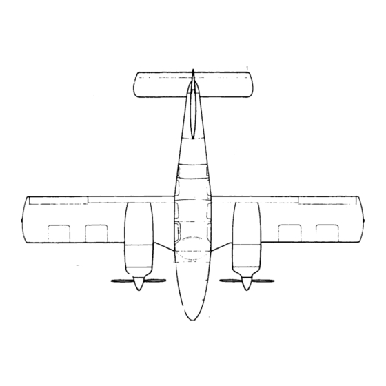
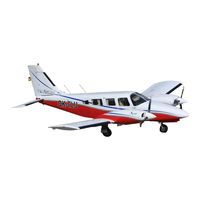
Piper PA-34-200T Seneca II Manuals
Manuals and User Guides for Piper PA-34-200T Seneca II. We have
2
Piper PA-34-200T Seneca II manuals available for free PDF download: Service Manual
Piper PA-34-200T Seneca II Service Manual (676 pages)
CARD 1 OF 3
Brand:
Piper
| Category:
Tools
| Size: 30 MB
Table of Contents
Table of Contents
3
Aerofiche Card no
5
List of Illustrations
5
Introduction
13
Handling and Servicing
16
Access and Inspection Provisions
18
Serial Number Plate
18
Station Reference Lines
18
Tools and Test Equipment
18
Weight and Balance Data
18
Three View
19
Station References
20
Leading Particulars and Principal Dimensions
21
Torque Requirements
24
Torque Wrench Formula
25
Torque Wrenches
25
Recommended Torque Values
26
Flare Fitting Torque Chart
28
Thread Lubricants
28
Access Plates and Panels
29
Ground Handling
31
Introduction to Ground Handling
31
Jacking
31
Step, Handhold and Walkways
31
Leveling
32
Weighing
32
Locking Airplane
33
Mooring
33
Parking
34
Taxiing
34
Towing
34
External Power Receptacle
35
Filling Fuel Tanks
35
Fuel System
35
Operation of External Power Receptacle
35
Servicing
35
Draining the Fuel System
36
Handling of Moisture in Fuel System
36
Brake System
37
Filling Brake Cylinder Reservoir
37
Oleo Struts
37
Servicing Brake System
37
Filling Nose Gear Oleo Strut
39
Filling Main Gear Oleo Struts
41
Hydraulic System
43
Inflating Oleo Struts
43
Servicing Steering Bungees
43
Servicing Tires
43
Battery
44
Cleaning
44
Servicing Hydraulic Pump/Reservoir
44
Cleaning Exterior Surfaces
45
Cleaning Headliner, Side Panels and Seats
45
Cleaning Landing Gear
45
Cleaning Windshield and Windows
45
Cleaning Carpets
46
Draining Oil Sump
46
Lubrication
46
Oil Filter (Full Flow)
46
Oil Screen (Suction)
46
Oil System (Engine)
46
Servicing Oil System
46
Lubrication Instructions
47
Recommendations for Changing Oil
47
Application of Grease
48
Lubrication Charts
48
Type of Lubricants
49
Lubrication Chart (Landing Gear, Main)
50
Lubrication Chart (Control System)
52
Lubrication Chart (Power Plant & Propeller)
54
Conversion Tables
56
List of Consumable Materials
63
Inspection
71
Inspection Requirements
72
Preflight Check
72
Recommended Lubricants
72
Inspection Report
74
Structures
84
Hose/Line Markings
88
Flareless Tube Assemblies
89
Identification of Fluid Lines
89
Flareless-Tube Fittings
90
Maximum Distances between Fluid Tubing Supports
91
Maximum M Resistance Values Allowed for Electrical Bonding
91
Electrical Bonding
92
Support Clamps Information
92
Wing Tip
92
Installation of Aileron
93
Installation of Wing Flap
93
Installation of Wing Tip
93
Removal of Aileron
93
Aileron and Flap Installation
94
Removal of Wing
96
Wing Installation
97
Empennage Group
100
Removal of Stabilator
100
Installation of Stabilator Trim Tab
101
Installation of Stailator
101
Removal of Stabilator Trim Tab
101
Installation of Rudder
106
Removal of Rudder
106
Removal of Rudder Trim Tab
106
Installation of Rudder Trib Tab
107
Removal of Vertical Fin
107
Installation of Vertical Fin
108
Installation of Windshield
108
Removal of Windshield
108
Installation of Windows
110
Removal of Windows
110
Installation of Rear Door Window
111
Removal of Rear Door Window
111
Removal and Installation of Door Snubbers
113
Installation of Door
116
Removal of Door
116
Adjustment of Door
117
Installation of Door Latch Mechanism
117
Removal of Door Latch Mechanism
117
Removal of Door Lock Assembly
117
Installation of Baggage Door
118
Installation of Baggage Door Hinge
118
Rigging Instructions - Seat Back Lock and Release
118
Shoulder Harness Inertia Reel Adjustment
118
Fiberglass Repairs
120
Fiberglass Touch-Up and Surface Repairs
120
Structural Repairs
120
Fiberglass Fracture and Patch Repairs
122
Skin Material and Thickness
123
Thermoplastic Repairs
125
Deep Scratches, Shallow Nicks and Small Holes
128
Surface Scratches, Abrasions or Ground-In-Dirt
128
Mixing of Epoxy Patching Compound
129
Welding Repair Method
129
Repairing of Cracks
130
Various Repairs
131
Repair of Impacted Damage
132
Repair of Stress Lines
132
Application of Liquid Safety Walk Compound
133
Product Listing for Liquid Safety Walk Compound
133
Safety Walk Repair
133
Surface Preparation for Liquid Safety Walk
133
Application of Pressure Sensitive Safety Walk
134
Surface Preparation for Pressure Sensitive Safety Walk
134
Balancing Equipment
135
Checking Control Surface Balance
135
Control Surface Balancing
135
Control Surface Balance Tool
136
Balance Specifications
137
Balancing Ailerons
137
Balancing Rudder
137
Aileron and Rudder Balance Configuration
138
Balancing Stabilator
139
Checking Free Play of Control Surfaces
139
Stabilator Balance Configuration
139
Surface Controls
141
Control Surface Travels and Cable Tensions
143
Cable Tension Vs. Ambient Temperature
144
Control Column Assembly
146
Installation of Control Column Assembly
146
Removal of Control Column Assembly
146
Aileron Controls
147
Removal of Aileron Control Cables
147
Correct Method of Installing Rod End Bearing
148
Installation of Aileron Control Cables
151
Installation of Aileron Bellcrank Assembly
152
Removal of Aileron Bellcrank Assembly
152
Riggin and Adjustment of Aileron Controls
153
Aileron Rigging Tool
154
Removal of Stabilator Control Cables
155
Stabilator Controls
155
Stabilator and Stabilator Trim Controls
157
Rigging and Adjustment of Stabilator Controls
160
Removal of Stabilator Trim Assembly (Forward)
161
Stabilator Trim Controls
161
Installation of Stabilator Trim Assembly (Forward)
162
Removal of Stabilator Trim Controls (Aft)
163
Installation of Stabilator Trim Controls (Aft)
164
Rigging and Adjustment of Stabilator Trim
164
Installation of Rudder Pedal Assembly
165
Removal of Rudder Pedal Assembly
165
Rudder Pedal Assembly
165
Rudder and Brake Pedal Assembly
166
Removal of Rudder Control Cables
167
Rudder Controls
167
Installation of Rudder Control Cables
168
Rudder and Rudder Trim Controls
169
Rigging and Adjustment of Rudder Controls
171
Rudder and Stabilator Travel Adjustment
172
Installation of Rudder Trim Controls
173
Removal of Rudder Trim Controls (Forward)
173
Rudder Trim Controls
173
Installation of Rudder Trim Controls (Aft)
174
Removal of Rudder Trim Controls (Aft)
174
Rigging and Adjustment of Rudder Trim Controls
175
Removal of Wing Flap Controls
176
Flap Controls
177
Installation of Wing Flap Controls
178
Flap Rigging Tool
179
Flap Step Adjustment
179
Rigging and Adjustment of Wing Flaps
179
Fabricated Aileron Bellcrank Rigging Tool
181
Fabricated Stabilator Rigging Tool
183
Fabricated Rudder Rigging Tool
184
Troubleshooting Chart (Surface Controls)
185
Hydraulic System
195
Disassembly of Hydraulic Pump
198
Removal of Hydraulic Pump
198
Schematic Diagram of Hydraulic System
199
Hydraulic System Installation
200
Assembly of Hydraulic Pump
201
Cleaning. Inspection and Repairs of Hydraulic Pump
201
Test and Adjustment of Hydraulic Pump
202
Hydraulic Pump/Reservoir, Exploded View
203
Characteristics, Hydraulic Pump Motor
204
Leading Particulars, Hydraulic Pump
204
Installation of Hydraulic Pump
205
Landing Gear Free-Fall Valve Assembly
205
Removal of Free-Fall Valve Assembly
205
Test and Adjustments of Hydraulic Pump
206
Gear Actuating Cylinder
207
Installation of Free-Fall Valve Assembly
207
Removal of Nose Gear Actuating Cylinder
207
Disassembly of Actuating Cylinder
208
Removal of Main Gear Actuating Cylinder
208
Installation of T-Rings
209
End Gland Locking Device
210
Assembly of Gear Actuating Cylinder
211
Cleaning. Inspection and Repair of Gear Actuating Cylinder
211
Hydraulic Lines
212
Installation of Main Gear Actuating Cylinder
212
Installation of Nose Gear Actuating Cylinder
212
Testing Hydraulic System
213
Troubleshooting Chart (Hydraulic System)
214
Landing Gear and Brake System
221
Cleaning, Inspection and Repair of Noise Gear Oleo
224
Disassembly of Nose Gear Oleo
224
Nose Landing Gear
224
Nose Gear Oleo Strut Assembly
225
Nose Gear Service Tolerances
228
Assembly of Nose Gear Oleo
231
Removal of Nose Landing Gear
231
Nose Gear Installation
232
Cleaning, Inspection and Repair of Nose Landing Gear
237
Installation of Nose Landing Gear
237
Alignment of Nose Landing Gear
241
Cleaning, Inspection and Repair of Nose Gear Door Assembly
241
Removal of Nose Gear Door Assembly
241
Installation of Nose Door Assembly
242
Adjustment of Nose Gear Door
243
Cleaning, Inspection and Repair of Main Gear Oleo
243
Main Landing Gear System
243
Main Gear Oleo Strut Assembly
244
Assembly of Main Gear Oleo
248
Cleaning, Inspection and Repair of Main Landing Gear
249
Removal of Main Landing Gear
249
Main Gear Installation
250
Installation of Main Landing Gear
252
Adjustment of Main Landing Gear
253
Alignment of Main Landing Gear
254
Cleaning, Inspection and Repair of Main Gear Door Assembly
255
Installation of Main Gear Door Assembly
255
Removal of Main Gear Door Assembly
255
Toe-In - Toe-Out Correction Chart
255
Aligning Main Gear
256
Toe-In/Toe-Out Adjustment
257
Adjustment of Main Gear Door Assembly
258
Adjustment of Nose Gear down Limit Switch
258
Adjustment of Nose Gear up Limit Switch
258
Landing Gear Limit Switches
258
Adjustment of Main Gear down Limit Switch
259
Adjustment of Landing Gear Up/Power Reduced Warning Switch
260
Landing Gear Up/Power Reduced Warning Switch
260
Switch Location
260
Assembly and Installation of Nose Wheel
263
Inspection of Nose Wheel Assembly
263
Removal and Disassembly of Nose Wheel
263
Nose Wheel Assembly
265
Removal and Disassembly of Main Wheel
265
Bearing Cup Replacement
266
Inspection of Main Wheel Assembly
266
Removal and Disassembly of Wheel Brake Assembly
266
Wheel Brake Assembly
266
Cleaning, Inspection and Repair of Wheel Brake Assembly
267
Removal and Installation of Anchor Bolts
269
Assembly and Installation of Wheel Brake Assembly
270
Brake Master Cylinder (Hand Parking Brake)
271
Cleaning, Inspection and Repair of Brake Master Cylinder
271
Disassembly of Brake Master Cylinder
271
Removal of Brake Master Cylinder
271
Brake System Installation
272
Brake Cylinder (10-27) (Toe Brake)
273
Brake Cylinder (17000) (Toe Brake)
273
Assembly of Brake Master Cylinder
274
Brake Cylinder (10-30) (Toe Brake)
274
Installation of Brake Master Cylinder
274
Cleaning, Inspection and Repair of Brake Cylinder
275
Disassembly of Brake Cylinder
275
Removal of Brake Cylinder
275
Brake Bleeding Procedure
277
Installation of Brake Cylinder
277
Bleeding Brake
278
Brake Reservoir
278
Brake System Leak Check
278
Troubleshooting Chart (Landing Gear)
279
1J5
286
Fabricated Pointer
287
Magneto Assembly
287
Timing Kit Installed
287
Aerofiche Card no
290
Power Plant
292
Description
294
Introduction
294
Power Plant
294
Cleaning, Inspection and Repair of Engine Cowling
295
Engine Cowling
295
Installation of Engine Cowling
295
Removal of Engine Cowling
295
Troubleshooting
295
Engine Cowl Flaps
296
Operation and Adjustment of Cowl Flaps
296
Cowl Flap Installation
297
Engine Cowling Installation
297
Cleaning, Inspection and Repair of Propeller
298
Removal of Propeller
298
Propeller Installation
299
Installation of Propeller
300
Typical Nicks and Removal Method
300
Propeller Specifications
301
Checking Propeller Blade Track
302
Installation of Propeller Governor
302
Removal of Propeller Governor
302
Rigging and Adjustment of Propeller Governor
302
Powerplant
303
Propeller Governor
303
Removal of Engine
305
Engine Installation
306
Turbocharger
306
Replacement of Engine Shock Mounts
308
Turbocharger
309
Turbocharger Nomenclature
309
Installation of Turbocharger
311
Removal of Turbocharger
311
Schematic Diagram of Turbocharger System
312
Adjustment of Turbocharger
313
Cleaning Induction Air Filter
313
Induction System Air Filter
313
Induction System Installation
313
Removal of Air Filter
313
Alternate Air Door
314
Ignition System
314
Installation of Air Filter
314
Magnetos
314
Inspection of Magnetos
315
Magneto Assembly
316
Magneto Timing Procedure
317
Removal of Magneto
317
Contact Spring Inspection
318
Contact Points
319
Impulse Coupling
319
Flyweight Clearance of Impulse Coupling
320
Magneto Installation and Timing Procedure (Magneto to Engine)
321
Rotor Holding Tool Installed
321
Powerplant
322
Cast-In Timing Marks
322
Engine Timing Marks
324
Harness Assembly
324
Inspection of Harness
324
Maintenance of Harness
325
Removal of Harness
325
Removing Spring from Lead Assembly
326
Assembly Tool Application
327
Measuring Lead Assembly Length
327
Installing Grommet over Lead Assemblies
329
Measuring Wire from Top of Ferrule
329
Lead Assembly Installed in Grommet
330
Wire Doubled over for Installation of Eyelet
330
Ignition Schematic
331
Installation of Harness
333
Removal of Spark Plugs
333
Inspection and Cleaning of Spark Plug
334
Removing Frozen Spark Plug
334
Installation of Spark Plugs
336
Lubrication System Description
336
Lubrication System Maintenance Points
337
Engine Fuel System Description
338
Fuel Injection System Maintenance
338
Schematic Diagram of Fuel Injection System
339
Fuel Injector Nozzle Assembly
340
Engine Controls
341
Engine and Propeller Controls
342
Rigging Throttle, Mixture and Governor Controls
342
Engine Setup Procedures
343
Idle Speed and Mixture Adjustment Points
343
Checking Fuel System Match
346
Flight Test
346
Sectional View of Altitude Compensating Fuel Pump Assembly
347
Fuel Flow Vs. Engine Speed
348
Exhaust Bypass Valve Screw
349
Limits - Fuel Flow Vs. Brake H.P.
350
Troubleshooting Chart (Engine)
351
Fuel System
359
2D4
359
Fuel System Schematic
362
Inspection and Repair of Fuel Tanks
363
Removal of Inboard Fuel Tank
364
Installation of Inboard Fuel Tank
364
Removal of Outboard Fuel Tank
364
Installation of Outboard Fuel Tank
364
Removal of Optional Fuel Cell
365
Installation of Optional Fuel Cell
366
Cleaning and Inspection of Fuel Cells
366
Fuel Cell Installation
367
Fuel Cell Compartment
368
Handling and Storage of Fuel Cells
368
Repair of Fuel Cells
368
Handling of Repair Materials
369
Repair Limitations of Fuel Cells
369
Repair Patch
370
Fuel Cell Repair Equipment Information
371
Defect Repairs of Fuel Cell
372
Testing Fuel Cells
372
Inspection of Fuel System
374
Fuel Quantity Sender Units
374
Fuel Quantity Sender/Gauge Check
374
Fuel Quantity Sender/Gauge Tolerances
375
Removal of Fuel Filter
376
Disassembly of Fuel Filter
376
Cleaning, Inspection and Repair of Fuel Filter
376
Assembly of Fuel Filter
377
Installation of Fuel Filter
377
Removal of Fuel Selector Valve
377
Disassembly of Fuel Selector Valve
377
Cleaning, Inspection and Repair of Selector Valve
378
Assembly of Selector Valve
378
Leak Test of Selector Valve
379
Installation of Fuel Selector Valve
379
Rigging of Selector Valve
379
Cleaning Fuel System
379
Auxiliary Fuel System Adjustment
380
Slider Resistor Terminal
380
Auxiliary Fuel System Operational Check
381
Calibration and Test of Fuel Quantity Gauges
381
Resistor Set-Up, Test for Fuel Quantity Gauge
382
Fuel Gauge Reading Tolerances
383
Maximum Deviation of Fuel Quantity Gauge Needle
383
Gauge Readings/Resistance
384
Troubleshooting Chart (Fuel System)
385
Instruments
387
Non-Electrical Instruments
390
Gyro Pressure System
390
Gyro Pressure Gauge
390
Pressure Regulating Valve
390
Pneumatic Pump Removal and Installation
394
Replacing Pneumatic Pump Fittings
394
Pitot-Static System
395
Directional Gyro
398
Directional Gyro Indicator
399
Gyro Horizon
399
Gyro Horizon Indicator
400
Rate of Climb Indicator
401
Sensitive Altimeter
402
Altimeter
402
Airspeed Indicator Troubleshooting
404
Airspeed Tubes and Indicator
404
Magnetic Compass
405
Adjustment of Compass
405
Manifold Pressure Gauge System
407
Manifold Pressure Indicator
408
Tachometer Indicator
408
Tachometer
409
Engine Oil Pressure Gauge
409
Electrical Instruments
411
Turn and Bank Indicator
411
Fuel Quantity Indicator
411
Oil Temperature Indicators
413
Removal and Replacement of Cluster Mounted Instruments
415
Exhaust Gas Temperature Gauge
415
Removal of Egt Probe and Gauge
415
Cylinder Head Temperature Gauge
417
Fuel Flow Gauge
417
Piper Autocontrol System
418
Instrument Markings
418
Annunciator Panel
418
Electrical System
419
Description
420
Troubleshooting
420
2F20
423
Alternator System
423
Switch Panel - Without Primer Switches
424
Switch Panel - with Primer Switches
425
2F23
426
Alternator and Components
426
Description of Alternator
426
2F24
427
Checking Alternator System
427
Overhaul of Alternator
428
2G2
429
Disassembly of Alternator
429
2G4
431
Inspection and Testing of Components
431
2G5
432
Assembly of Alternator
432
Installation of Rectifier
432
2G6
433
Testing Alternator
433
Alternator Nomenclature
435
2G9
436
Operation of Regulator
436
Regulator Components
436
Voltage Regulator
436
2G10
437
Balancing Circuit Operation
437
Preparation for Testing
438
2G12
439
Testing Regulator
439
Adjusting Regulator
440
2G14
441
Checking Overvoltage Relay
441
Overvoltage Relay
441
Application of Overvoltage Control
442
Testing Overvoltage Control
442
Starting Motors
443
Disassembly
444
Exploded View of Starting Motor
444
Armature
445
Brushes
445
Field Coils
445
Assembly
446
Brush Holders
446
Bench Tests
447
Starting Motor Control Circuit
447
Starting Motor Service Test Specifications
448
Removal of Battery
448
Servicing Battery
448
Installation of Battery
449
Battery Box Corrosion Prevention
450
Charging Battery
450
Hydrometer Reading and Battery Charge Percent
450
Installation of Landing and Taxi Lights
451
Landing and Taxi Lights
451
Removal of Landing and Taxi Lights
451
Stall Warning System
452
Adjusting Lift Detector Micro Switch
453
Installation of Lift Detector
454
Installation of Wing Navigation Light
454
Removal of Lift Detector
454
Removal of Wing Navigation Light
454
Installation of Lampp in Anti-Collision Wing Tip Strobe Light
455
Removal of Lamp in Anti-Collision Light
455
Removal of Lamp in Anti-Collision Wing Tip Strobe Light
455
Installation of Anti-Collision Light
456
Installation of Lamp in Overhead Reading Lights
456
Removal of Lamp in Overhead Reading Lights
456
Installation of Dimmer Control Assembly
457
Instrument and Panel Lights
457
Removal of Dimmer Control Assembly
457
Annunciator Lights Test
458
Troubleshooting Chart (Electrical System)
459
Electrical Wire Coding
472
Electrical Symbols
473
Electrical System Component Loads
474
Engine Gauges
481
Reading and Baggage Lights
484
Position Lights
486
Ventilation Air Blower
486
Heater and Defroster
487
Stall Warning
488
Stall Warning (Sensor Heaters)
488
Fuel Pumps (Auxiliary System)
489
Electronics
495
Battery Removal and Installation
496
Emergency Locator Transmitter
496
Two Year, Magnesium Battery Connections
497
Garrett ELT Schematic
498
Communications Components ELT Schematic
500
Emergency Locator Transmitter Schematic (Narco)
500
Testing Emergency Locator Transmitter
501
ELT Portable Folding Antenna (Narco)
502
ELT Using Fixed Aircraft Antenna (Narco)
502
Autoflight
503
Avionics Master and Emergency Switch Circuit
503
Heating and Ventilating System
505
Cabin Heater, Defroster and Fresh Air Installation
508
Combustion Heater (Janitrol)
509
Description of Heater and Basic Components
510
Fuel Regulator and Shutoff Valve
510
Heater and Combustion Air Blower Assembly (30,000 BTU)
511
Heater and Combustion Air Blower Assembly (45,000 BTU)
512
Combustion Air Blower
513
Duct Switch
513
Operating Controls
513
Ventilating Air Blower
513
Daily Inspection
514
Inspection of Heater and Heater Components
514
Maintenance Service
514
Operating Procedure
514
Top View - Duct Switch
515
100-Hour Inspection
516
3-17A. Overhaul Instructions
516
Installation of Heater
517
Removal of Heater
517
Heater Electrical System Checks
519
Vent Blower Power Circuit Check
520
Starting Power Circuit
521
Combustion Air Blower
522
General Maintenance
522
Spark Plug
523
Spark Plug Gap Adjustment
524
Ignition Unit Removal and Installation (30.000 BTU)
526
Ignition Unit Removal and Installation (45.000 BTU)
526
Operational Test of Ignition Unit
527
Vibrator Removal and Installation
527
Inspection of Ignition Unit
528
Vibrator
528
Cycling Switch and Limit Switch
529
Adjustment of Fuel Regulator
530
Combustion Air Pressure Switch
530
Removal of Fuel Regulator
530
Heater Fuel Pump Maintenance
531
Installation of Fuel Regulator
531
Removal of Heater Fuel Pump
531
Cleaning of Pump
532
Disassembly of Pump
532
Inspection and Repair of Pump
532
Duct Switch
533
Installation of Heater Fuel Pump
533
Cleaning
535
Disassembly of Combustion Air Blower Assembly (30.000 BTU)
535
Cleaning and Inspecting the Combustion Tube Assembly (30.000 BTU)
536
Inspection of Remaining Components (30,000 BTU)
536
Cleaning
539
Disassembly of Combustion Air Blower Assembly (45,000 BTU)
539
Test Setup for Combustion Air Pressure Switch
540
Cleaning and Inspecting the Combustion Tube Assembly (45,000 BTU)
541
Inspection of Remaining Components (45,000 BTU)
541
Exploded View of Heater Assembly (30,000 BTU)
544
Exploded View of Heater Assembly (45,000 BTU)
545
Repair of Combustion Tube Assembly
546
Reassembly of Combustion Air Blower Assembly (30.000 BTU)
548
Exploded View - Combustion Air Blower and Motor Assembly (30,000 BTU)
550
Exploded View - Combustion Air Blower and Motor Assembly (45.000 BTU)
551
General Information
552
Reassembly of Combustion Air Blower Assembly (45.000 BTU)
552
Suggested Setup of Heater Operation Test
553
Wiring Connections for Heater Operation Test
553
Equipment Required
554
Operation Test (on Test Bench)
554
Defroster Blower Removal and Installation
555
Inspection of Fuel Nozzle Orifice
555
Spark Plug Gap Adjustment Tool
556
Troubleshooting Chart (Janitrol Heater)
557
Aerofiche Card No. 2
566
Accessories and Utilities
566
Accessories and Utilities
573
Propeller Deicing System.
573
Deicer System Operational Check
574
Using the Ammeter
574
Propeller Deicing Installation
575
Electrical Diagram Showing Cycle Sequence
576
100 Hour Inspection
578
50 Hour Inspection
578
Typical Use of Dial Indicator
579
Brush Retainer Replacement
580
Alignment of New Brushes
581
Alignment of Slip Ring Assembly
581
Individual Brush Replacement
581
Replacement of Slip Ring Assemblies
581
Wiring Schematic - Electrical Prop Deicing System
582
Brush Block Assembly
583
Brush Module Replacement
584
Deicer Blades
584
Replacement of Brush Block with Modular Brush Assemblies
584
Resistance Check of Deicer Blade
584
Blade Preparation
589
Removal of Deicer
589
Installation of Deicer Boot
590
Required Materials for Repair of Propeller Deicer
590
Cement Application
591
Installation of Deicer and Required Materials
591
Mixing of Materials
592
Preparation and Application of Sealer
592
Electrical Check
593
Wrinkled Deicers
593
Electrical Resistance
594
Sealer Application (Boot)
594
Final Electric Check
595
Installation of Deicer Wiring Harness
595
Timer Test
595
Troubleshooting Chart (Propeller Deicer System)
596
Timer
598
Pneumatic Deicer System Installation
602
Pneumatic Deicing System
604
Pneumatic Deicer Boots Operation
605
Pneumatic Deicer System Schematic
605
Pneumatic Regulator Adjustment
606
Pressure Leakage Test
606
Control Valves
607
Filter Replacement
607
Inspections
607
Operating Pressures
608
Removal of Boots
609
Repair of Boots
609
Vulcanized Repairs
609
Cold Repair
610
Loose Surface Ply in Dead Area
610
Scuff Damage
610
Tube Area Damage
610
Material and Supplies for Cold Repair
611
Mounting Deicer on Leading Edge
613
Preparation of Leading Edges
613
Vulcanized Repairs
613
Adhesion Test
615
Icex Application
616
Resurfacing Conductive Cement
616
Troubleshooting Chart (Pneumatic Deicer System)
618
Description and Operation
620
Ice Detection Light
620
Ice Detection Light Schematic
620
Installation
620
Heated Windshield Panel
621
Removal and Installation of Heated Panel
621
Oxygen System
622
Cleaning Operations
623
Maintenance
623
Oxygen System Components Limits
624
Installation of Outlets
625
Removal of Outlets
625
Removal of Portable Oxygen Unit
625
Cleaning of Face Masks (Fixed System)
626
Removal of Oxygen Cylinder and Regulator (Fixed System)
627
Oxygen Tubing Installations
628
Oxygen Cylinder and Regulator Assembly
629
Oxygen System Filler Valve Installation
629
14-88A
630
Installation of Filler Valve
630
Installation of Oxygen Cylinder and Regulator (Fixed System)
630
Removal of Filler Valve
630
Installation of Pressure Gauge
631
Removal of Outlets
631
Removal of Pressure Gauge
631
Installation of Outlets
633
Thread Sealant
633
Air Conditioning Installation
634
Air Conditioning System Operation
634
Air Conditioning System Installation
635
Temperature Pressure Chart
636
Aluminum Tubing Torque
639
Service Valves
639
Test Gauge and Manifold Set
640
Manifold Set Operation
641
Checking the System for Leaks
642
Leak Check
642
Evacuation Hookup
644
Charging Stand
646
Using the Airplane Compressor to Charge the System
646
Adjustment of Drive Belt Tension
651
Receiver-Dehydrator Removal
651
Refrigerant Lines and Routing
651
Condenser Installation
652
Condenser Removal
652
Receiver-Dehydrator Installation
652
Condenser Scoop Rigging Instructions
653
Condenser Air Scoop Installation
654
Expansion Valve Installation
655
Expansion Valve Removal
655
Evaporator Assembly
656
Evaporator Assembly Installation
656
Evaporator Assembly Removal
656
Fuse Replacement
657
Pressure Relief Switch
657
Overhead Vent Blower
658
Blower System Wire Color Codes
659
Air Conditioning Wiring Schematic (Early Models)
660
Troubleshooting Chart (Air Conditioner)
661
Engine Synchrophaser
668
Inductor and Kit Installations
669
Synchrophasor System Check and Adjustment
669
Synchrophaser Wiring Schematic - Auto Synch/Manual Switch
670
Installation of Computer Assembly
673
Removal of Computer Assembly
673
Pulse Generator Installation
674
Advertisement
Piper PA-34-200T Seneca II Service Manual (869 pages)
Brand:
Piper
| Category:
Aircrafts
| Size: 22 MB
Table of Contents
Introduction Paragraph Grid No.
5
Table of Contents
5
Instructions for Continued Airworthiness
7
Serial Number Explanation
9
Assignment of Subject Material
9
Aerofiche Grid Numbering
9
Identifying Revised Material
12
Warnings, Cautions and Notes
13
Supplementary Publications
13
PIPER Publications
13
Vendor Publications
13
Section Index Guide
18
List of Illustrations
20
General
117
Accident/Incident Reporting
168
Paragraph Grid no
256
Section 2
325
Description
327
Introduction
327
Troubleshooting
328
Disassembly
333
Hydraulic Pump (Original Equipment - Prestolite)
333
Removal
333
1I9
335
Assembly
335
Cleaning, Inspection and Repair
335
1I10
336
Test and Adjustment
336
Hydraulic Pump (Service Replacement - Oildyne)
338
1I15
347
Gear Actuating Cylinder
347
Inspection and Repair
347
Installation
347
Landing Gear Free-Fall Valve Assembly
347
Removal
347
Removal of Nose Gear Actuating Cylinder
347
Disassembly of Actuating Cylinder
348
Removal of Main Gear Actuating Cylinder
348
Assembly of Gear Actuating Cylinder
351
Cleaning, Inspection and Repair of Gear Actuating Cylinder
351
1I20
353
Installation of Main Gear Actuating Cylinder
353
Installation of Nose Gear Actuating Cylinder
353
1I21
354
Hydraulic Lines
354
Removal and Installation of Hydraulic Lines
354
Servicing Hydraulic Pump/Reservoir
354
Testing Hydraulic System
354
Section 3
366
Disassembly
369
7-8A. Repair
374
Assembly
374
Nose Landing Gear
375
7-9B. Inspection
376
7-9C. Repair
379
Installation and Rigging
380
Removal
380
Alignment
386
Nose Gear Door Assembly
387
Removal
387
Adjustment
388
Inspection
388
Installation
388
Main Gear Oleo
388
Assembly
389
Disassembly
389
Main Landing Gear
395
Inspection
396
Installation
408
Removal
408
Landing Gear Warning Switch (Throttle Switch)
411
Adjustment of Landing Gear Up/Power Reduced Warning Switch 1K25
412
Replacement of Landing Gear Up/Power Reduced Warning Switch 1K25
412
Assembly and Installation of Nose Wheel
417
Inspection of Nose Wheel Assembly
417
Removal and Disassembly of Nose Wheel
417
Wheels
417
Removal and Disassembly of Main Wheel
418
Assembly and Installation of Main Wheel
419
Bearing Cup Replacement
419
Brake System
419
Inspection of Main Wheel Assembly
419
Wheel Brake Assembly
419
Removal and Disassembly
420
Assembly and Installation
423
Cleaning, Inspection and Repair
423
Brake Master Cylinder (Hand Parking Brake)
424
Disassembly
424
Removal
424
Assembly
426
Brake Cylinder (Toe Brake)
426
Cleaning, Inspection and Repair
426
Installation
426
Removal
426
Cleaning, Inspection and Repair
427
Disassembly
427
Assembly
428
Installation
428
Brake Bleeding Procedure (Gravity)
430
Brake Bleeding Procedure (Pressure)
431
Brake System Leak Check
431
Section 4
550
10-1A
554
General
554
Gyro Pressure System
554
Non-Electrical Instruments
554
Adjustments to Pressure Regulator
555
General
555
Gyro Pressure Gauge
555
Pressure Regulating Valve
555
Troubleshooting
555
Removal and Installation
556
2E14C
560
General
560
Pneumatic Pump
560
Troubleshooting
569
General
574
Troubleshooting
574
General
577
Troubleshooting
577
General
583
Troubleshooting
583
Removal and Replacement
588
Section 5
592
Alternator System
594
Description
594
Introduction
594
Troubleshooting
594
Alternator and Components
600
Description of Alternator
600
Checking Alternator System
601
Overhaul of Alternator
602
Service Procedures
602
Disassembly of Alternator
603
Inspection and Testing of Components
605
Assembly of Alternator
606
Testing Alternator
607
Alternator Nomenclature
609
Alternator Service Test Specifications
609
Operation of Regulator
610
Regulator Components
610
Voltage Regulator
610
Balancing Circuit Operation
611
Preparation for Testing
612
Testing Regulators
613
Checking Overvoltage Relay
615
Overvoltage Relay
615
Operation
617
Starting Motors
617
Field Coils
619
Assembly
620
Brush Holders
620
Bench Tests
621
Starting Motor Control Circuit
621
Starting Motor Service Test Specifications
622
Section 6
690
Heater Fuel Pump Maintenance
715
Installation of Fuel Regulator 2K8
715
Cleaning of Pump
716
Disassembly of Pump
716
Inspection and Repair of Pump 2K9
716
Assembly of Pump
717
Duct Switch
717
Installation of Heater Fuel Pump 2Kl0
717
Cleaning
719
Disassembly of Combustion Air Blower Assembly (30,000 BTU)
719
Cleaning and Inspecting the Combustion Tube Assembly (30,000 BTU)
720
Disassembly (45,000 BTU Heater)
722
Disassembly of Combustion Air Blower Assembly (45,000 BTU)
723
Cleaning
725
Reassembly (30,000 BTU)
731
Reassembly of Combustion Air Blower Assembly (30,000 BTU)
732
(45,000 Btu) 2L5
736
General Information
736
Reassembly (45,000 BTU)
736
Advertisement
Related Products
Piper Cheyenne IIXL PA-31T2 1981
Piper PA-28R-200
Piper PA-32-301 Saratoga
Piper Cherokee Arrow II PA-28R-200 1973
Piper APACHE PA-23-235
Piper AZTEC PA-23-250
Piper Malibu Meridian PA-46-500TP
Piper PA-44-180T TURBO SEMINOLE
Piper TWIN COMANCHE PA-30
Piper PA-44-180 Seminole 1979
Piper Categories
Aircrafts
Tools
Toy
Commercial Food Equipment
Oven
More Piper Manuals
Login
Sign In
OR
Sign in with Facebook
Sign in with Google
Upload manual
Upload from disk
Upload from URL