EASTONTECH EW Series Operation Manual
Crimping machine
Hide thumbs
Also See for EW Series:
- Operation manual (27 pages) ,
- Operation manual (13 pages) ,
- Operation manual (11 pages)
Advertisement
Quick Links
EW-5010A OPERATION MANUAL
Edition No.: 2021 Rev 2
WENZHOU EAST WORLD IMPORT&EXPORT CO., LTD.
(CE, ISO9001)
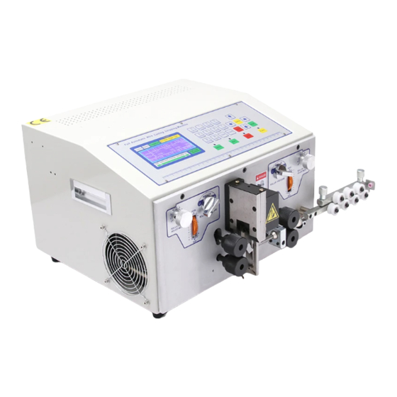
EW Series Insulation Ferrule
Crimping Machine
Operation Manual
(FOR EW-5010A)
Add:Building No.2 丨 Xingdong Industrial Park 丨 NO.188 Wangxin Road 丨 Dongshan
Street 丨 Ruian 丨 Zhejiang Province 丨 China P.C.-325200
Website: www.ew-wirestripping.com
Email:kitty@ew-wirestripping.com
Tel/Fax:+86-0577-66603688
1
Advertisement

Related Manuals for EASTONTECH EW Series


Summary of Contents for EASTONTECH EW Series
- Page 1 EW-5010A OPERATION MANUAL Edition No.: 2021 Rev 2 WENZHOU EAST WORLD IMPORT&EXPORT CO., LTD. (CE, ISO9001) EW Series Insulation Ferrule Crimping Machine Operation Manual (FOR EW-5010A) Add:Building No.2 丨 Xingdong Industrial Park 丨 NO.188 Wangxin Road 丨 Dongshan Street 丨 Ruian 丨 Zhejiang Province 丨 China P.C.-325200 Website: www.ew-wirestripping.com...
- Page 2 EW-5010A OPERATION MANUAL Machine removal and installation 1. After taking out the machine, confirm whether there is any transportation damage or other mechanical parts falling off in the machine box. 2. After the machine is taken out, open the right box door and remove the internal transport fixed part of the cable tie (as shown below left), and take out the jig accessory box in the rubber waste box.
- Page 3 EW-5010A OPERATION MANUAL Parameter Name Pre insulation terminal crimping machine Model EW-5010A human-machine interface, electronic control, pneumatic Control mode control. Operation mode Automatic trigger operation and manual operation Wire size BVR wire 0.5、0.75、1.0、1.5、2.5、4.0mm2 Terminal size Insulator length ≤7.5mm, conductor length≤10mm Stripping length Max.
- Page 4 EW-5010A OPERATION MANUAL ⅠInterface introduction 1.1 Home screen function introduction 1-1-1. Total production: The quantity counted by the machine during production operation in automatic mode. 1-1-2. Total reset: reset the total output; the total reset button can be displayed or closed in the administrator settings interface, but it will be displayed automatically when the total production reaches the standard.
- Page 5 EW-5010A OPERATION MANUAL the automatic case, the cycle time is parallel to the manual take-up and release time); The setting interface settings are displayed or closed. 1-1-5. Peeling settings: pull down the menu key, see the related interface for details. 1-1-6.
- Page 6 EW-5010A OPERATION MANUAL 1.2 Manual control Introduction 1-2-1. Enter this interface: main screen → manual control. 1-2-2. 9 green buttons are jog self-locking switches, which need to be jogged again to unlock; the initial state when OFF, and the output state when ON;...
- Page 7 EW-5010A OPERATION MANUAL equivalent to the automatic triggering of the line. 1-2-5. Main screen: Return to the main interface.
- Page 8 EW-5010A OPERATION MANUAL 1.3 Stripping Setting 1-3-1. Enter this interface: main screen → peeling settings. 1-3-2. There are a total of 6 wire number specifications for the peeling setting. There is a corresponding settable value for each wire number. Shallower. 1-3-3.
- Page 9 EW-5010A OPERATION MANUAL depth or length, all are modified. Click "Modify Confirmation" to adjust the actual position. After clicking Modify Confirmation, this key will prompt the progress, and the selection or value cannot be modified at this time. 1-3-6. After the machine is installed, the stripping depth and corresponding stripping length of each line can be adjusted according to different wire numbers.
- Page 10 EW-5010A OPERATION MANUAL 1.4 Parameter set 1-4-1. enter this interface: main screen → parameter setting. 1-4-2. the above setting time is the time between sequence, setting value × 10ms, except above special circumstances, no modification is needed for the time being. 1-4-3.
- Page 11 EW-5010A OPERATION MANUAL 1-4-4. Enter this interface: main screen → parameter setting → next page. 1-4-5. The above setting time is the time between sequence, setting value × 10ms. Except for special cases, the above time does not need to be modified.
- Page 12 EW-5010A OPERATION MANUAL 1-4-8. Enter this interface: main screen → parameter setting → next page → next page. 1-4-9. Delay start time of wire release touch: It can change the sensitivity of wire release trigger. The smaller the value is, the more sensitive it is. 1-4-10.
- Page 13 EW-5010A OPERATION MANUAL 1.5 IO monitoring 1-5-1. Enter this interface: main screen → parameter setting → IO monitoring. 1-5-2. Under normal standby conditions, only the above 4 input monitors are displayed in red and the others are gray. 1-5-3. Main screen: Return to the main interface.
- Page 14 EW-5010A OPERATION MANUAL ⅡChange product adjustment 2.1 Vibration plate feed adjustment (Figure 212) (Figure 213) (Figure 214) 2-1-1. Figure 211 are the names of the parts supplied by the vibrating plate. 2-1-2. Figure 212 shows the controller of the vibrating disk. This screen shows the voltage H100.
- Page 15 EW-5010A OPERATION MANUAL Observe whether to adjust. 2-1-3. Figure 213 This screen is displayed as frequency E50; only frequency E50 and E100 are selected. A frequency E50 has been selected when the machine leaves the factory, so no adjustment is required when changing terminals (except for special cases).
- Page 16 EW-5010A OPERATION MANUAL After 1.0 square is adjusted, 0.75 and 0.5 square can also be used; 1.5 and 2.5 squares can use 2.5 squares as a reference for adjusting the width. After adjusting 2.5 squares and using them, 1.5 and 2.5 squares can also be used (the above general may be related to changes in the size of each manufacturer's terminal specifications).
- Page 17 EW-5010A OPERATION MANUAL and the middle U port are to the right of the discharge direction; (see Figure 217). Can be replaced by loosening M3-6 bolts . 2-1-10. Confirm the terminal specifications and whether to replace them. There are three types of terminal guides: 0.5, 0.75, 1.0 square for the smallest U port, 1.5, 2.5 square for the middle U port, and 4.0 square for the maximum U port.
- Page 18 EW-5010A OPERATION MANUAL 2.2 Gig box...
- Page 19 EW-5010A OPERATION MANUAL 2.3 Change jig and adjust (Figure 221) (Figure 222) 2-3-1. Confirm the terminal specifications. There are 6 specifications for the terminal guide rings of 0.5, 0.75, 1.0, 1.5, 2.5, and 4.0 square. 2-3-2. Figure 221, loosen the terminal guide ring M2.5-21.5 bolts (just loosen one turn), and then tighten the specifications required for replacement.
- Page 20 EW-5010A OPERATION MANUAL guides A and B must be flush with each other. Observe whether the slopes of the guide cones completely match.
- Page 21 EW-5010A OPERATION MANUAL 2.4 Clip adjustment 2-4-1. The clamp width can be adjusted according to the size of the wire. If necessary,you can record the scale of each line number independently. 2-4-2. If the wire is not damaged during clamping, it can be adjusted.
- Page 22 EW-5010A OPERATION MANUAL Ⅲ Fault inspection and treatment 3.1 Alarm content and processing method Item Alarm contents Processing method Open the right door to ensure In the case of tuning, you can turn off the detection in safety before powering on! the administrator settings interface.
- Page 23 EW-5010A OPERATION MANUAL The gel box is full. Please The number of colloid particles can be modified reset after clearing. according to the size of the colloid particles. The gel particle or trigger Check whether there is rubber particles or the trigger induction is abnormal.
- Page 24 EW-5010A OPERATION MANUAL Ⅳ Maintenance 4-1. It is forbidden to blow a certain position of the machine with an air gun. If it is blown with a wind gun, it may cause a control short circuit or damage to the mechanical structure. Only use a vacuum cleaner or a rag to clean.
Need help?
Do you have a question about the EW Series and is the answer not in the manual?
Questions and answers