Table of Contents
Advertisement
Quick Links
Datalogic S.r.l.
Via S. Vitalino, 13
40012 Calderara di Reno (BO)
Italy
Tel. +39 051 3147011
Fax +39 051 3147205
©2022 Datalogic S.p.A. and/or its affiliates
All rights reserved. Without limiting the rights under copyright, no part of this
documentation may be reproduced, stored in or introduced into a retrieval sys-
tem, or transmitted in any form or by any means, or for any purpose, without the
express written permission of Datalogic S.p.A. and/or its affiliates.
Owners of Datalogic products are hereby granted a non-exclusive, revocable
license to reproduce and transmit this documentation for the purchaser's own
internal business purposes. Purchaser shall not remove or alter any proprietary
notices, including copyright notices, contained in this documentation and shall
ensure that all notices appear on any reproductions of the documentation.
Electronic versions of this document may be downloaded from the Datalogic
website (www.datalogic.com). If you visit our website and would like to make
comments or suggestions about this or other Datalogic publications, please let
us know via the "Contact" page.
Disclaimer
Datalogic has taken reasonable measures to provide information in this manual
that is complete and accurate, however, Datalogic shall not be liable for technical
or editorial errors or omissions contained herein, nor for incidental or conse-
quential damages resulting from the use of this material. Datalogic reserves the
right to change any specification at any time without prior notice.
Trademarks
Datalogic and the Datalogic logo are registered trademarks of Datalogic S.p.A. in
many countries, including the U.S.A. and the E.U.
PowerScan is a trademark of Datalogic S.p.A. and/or its affiliates, registered in
the U.S. All other trademarks and brands are property their respective owners.
Patents
See www.patents.datalogic.com for patent list.
This product is covered by one or more of the following patents:
Utility patents: US10915476.
CM96XX
Quick Reference Guide
Multi Interface
Connection Module
©2022 Datalogic S.p.A. and/or its affiliates • All rights reserved •
Without limiting the rights under copyright, no part of this documen-
tation may be reproduced, stored in or introduced into a retrieval sys-
tem, or transmitted in any form or by any means, or for any purpose,
without the express written permission of Datalogic S.p.A. and/or its
affiliates • Datalogic and the Datalogic logo are registered trade-
marks of Datalogic S.p.A. in many countries, including the U.S. and
the E.U.
www.datalogic.com
820123301
Rev. B
March 2022
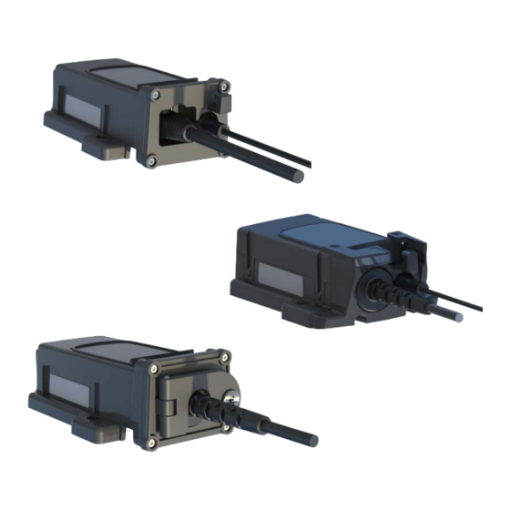
USING CM96XX
The CM96XX connection module is a modular component of the BC96XX
which provides power and communication between the host and the
base station.
It is mainly used as a replacement part for the BC96XX Base Station. The
CM9680 can also be used as an accessory to connect a PD96XX reader
to an Ethernet host.
The available models are:
•
CM9630 CONN Model Multi interface
•
CM9631 CONN Model Multi Interface IP65
•
CM9680 CONN Model Ethernet
CM96XX REPLACEMENT
To replace a CM96xx connection module in a BC96xx base station follow
the steps below:
1. Unscrew the
connection
module from the cradle.
2. Unlock the lever and remove the connection module from the cradle.
3. Replace the module by inserting it into the cradle, lock the lever and
screw the module to the cradle.
For other base station mounting solutions see the BC96xx Quick Refer-
ence Guide or the PowerScan 9600 Family PRG.
CM9680 Accessory for PD96xx Readers
The CM9680 can be used as an accessory for those who want to use an
Ethernet interface with a PD96XX gun.
RS232 cable
Mounting screws
position
TECHNICAL SPECIFICATIONS
ELECTRICAL CHARACTERISTICS
When used with BC96XX
CM9630: Host power 5VDC +-5% (*) or 10-30 Vdc +-5%
External power 10-30 VDC +-5%
Supply Voltage
CM9631: Host power 5VDC +-5% (*) or 10-30 Vdc +-5%
CM9680: External power 5VDC +-5% or 10-30 Vdc +-5%.
When used as a separate accessory
CM9680: External power 5 -30 Vdc +-5%
(*) with approved interface cables
Power Consumption
1.5 A max
CM9680:
-
BF LED (red/green): network status;
Indicators
-
LINK LED (yellow/green): link activity;
-
SF LED (red/green): module status;
-
PWR LED (green): power ON (this LED
is not visible when installed in the cra-
dle).
ENVIRONMENTAL CHARACTERISTICS
Working Temperature
-20° to +50 °C / -4 to +122 °F
Storage
-40° to +70 °C / -40 to +158 °F
Temperature
Humidity
90% non condensing
CM9630 and CM9631 can only be used together with the base
station BC96XX. Refer to BC96XX Quick Reference Guide for
Protection Class
protection class information.
CM9680 used alone as an accessory: IP40
Advertisement
Table of Contents

Related Manuals for Datalogic CM96 Series


Summary of Contents for Datalogic CM96 Series
- Page 1 Disclaimer Datalogic has taken reasonable measures to provide information in this manual Mounting screws that is complete and accurate, however, Datalogic shall not be liable for technical position or editorial errors or omissions contained herein, nor for incidental or conse- quential damages resulting from the use of this material.
- Page 2 European Declaration of Conformity sions as described in the Radio Interference Regulations of the Canadian Hereby, Datalogic S.r.l. declares that the full text of the European Decla- Department of Communications. ration of Conformity is available at: www.datalogic.com. Select the Sup- Le présent appareil numérique n’émet pas de bruits radioélectriques...
Need help?
Do you have a question about the CM96 Series and is the answer not in the manual?
Questions and answers