Table of Contents
Advertisement
Advertisement
Table of Contents

Related Manuals for Datalogic SG-BWS-T4


Summary of Contents for Datalogic SG-BWS-T4
- Page 2 SG BWS-T4 Instruction Manual Ed.: 01/2018 Rev. B © 2012 – 2018 Datalogic S.p.A. and/or its affiliates ALL RIGHTS RESERVED. Without limiting the rights under copyright, no part of this documentation may be reproduced, stored in or introduced into a retrieval system, or transmitted in any form or by any means, or for any purpose, without the express written permission of Datalogic S.p.A.
- Page 3 European directive. Since the directives and applicable standards are subject to continuous updates, and since Datalogic promptly adopts these updates, therefore the EU declaration of conformity is a living document. The EU declaration of conformity is available for competent authorities and customers through Datalogic commercial reference contacts.
-
Page 4: Table Of Contents
Complete list of connections .......................... 16 4.5. Connecting the safety photocells: ........................17 4.6. Connecting the safety photocells for SG-BWS-T4-2 model: ................18 4.7. Connecting the external relays and EDM ...................... 19 4.8. Reset mode and connection of the Start/Test/Reset push-button ..............20 5. -
Page 6: General Information
The instructions for use given herein are addressed to designers, manufacturers and persons in charge of the safety of systems to be equipped with the SG-BWS-T4. They are also addressed to the staff in charge of installing the SG-BWS-T4 to a machine, commissioning it or servicing it. -
Page 7: Product General Description
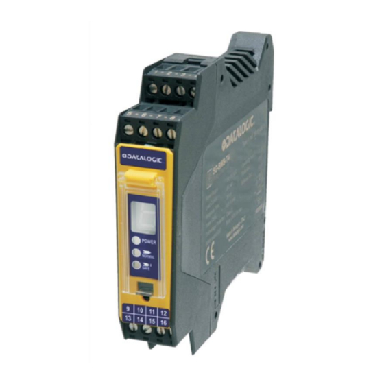
Fig. 1 SG-BWS-T4-MT Appearance and user interface SG-BWS-T4 safety system consists of a control unit enclosed in a plastic housing to be installed on OMEGA/DIN rail equipped with 16 screw clamps that can be connected up to 4 sets of photocells of the S5-ST, SL5-ST, S300 series. -
Page 8: Safety Sensors
S300-5-X-X-ST4: Type 4 safety photocell for long-distance applications. See section 10 “Order data” for further details about available photocell models. Using the above photocells independently from SG-BWS-T4 does not meet EN 61496-1 and CLC/TS 61496-2 requirements and is thus not allowed. -
Page 9: Main Functions Managed By The Control Unit
2.5. Typical Applications The SG-BWS-T4 system is typically used as a protection to the access to dangerous areas on machines or systems. The sensors are fixed and installed to the access area at the suitable safety distance from the nearest danger source and output a stop control to the machine or system, if the light beam is interrupted. - Page 10 Fig. 4 Doors control by means of safety photocelss Solution: SG-BWS-T4 is able to detect the door opening by using one or more photocells by intersecting the interrupted beams, guaranteeing the safety condition. Advantages: all the safety interlocks can be replaced on each door thanks to the use of photocells...
-
Page 11: Installation
INSTALLATION 3.1. Safety information For a correct and safe use of the SG-BWS-T4, the points considered in this section must be observed. The stopping system of the machine must be electrically controlled. This control system must be able to stop the dangerous movement of the machine within the total machine stopping time T as per par. -
Page 12: Minimum Installation Distance
Speed of the object, limb or body approaching the dangerous area in mm/s SG-BWS-T4 response time in seconds (0.029) The higher response time of all times for the safety sensors connected to SG-BWS-T4 Machine stopping time in seconds Resolution of the system. - Page 13 EN 13855. Example: light curtain with 4 S5 photocells S = K (t1 + t2 + t3) + C where: SG-BWS-T4 response time 29 ms S5 response time 1.5 ms machine total stopping time 290 ms 850 mm for devices with resolution ≥...
-
Page 14: Minimum Distance From Reflecting Surfaces
SG-BWS-T4 3.5. Minimum distance from reflecting surfaces Reflecting surfaces placed near the light beams of the safety device (over, under or laterally) can cause passive reflections. These reflections can compromise the recognition of an object inside the controlled area. However, if the RX receiver detects a secondary beam (emitted again by the side-reflecting surface) the object might not be detected, even if the object interrupts the main beam. -
Page 15: Sensors Interference
When several safety devices must be installed in adjacent areas, interference between the emitter of one device and the receiver of the other must be avoided. SG-BWS-T4 monitors possible interference between photocells and locks out if any interference is detected. -
Page 16: Installing The Safety Control Unit
3.7. Installing the safety control unit The SG-BWS-T4 control unit is simply installed onto an OMEGA/DIN rail placed inside a control panel. Fig. 10 Safety Control Unit mounting The 4 4-pole connection terminals can be disconnected quite easily using a flat-blade screwdriver and can be connected by hand. - Page 17 SG-BWS-T4 Use of deviating mirrors The control of any dangerous area, with several but adjacent access sides, is possible using only one safety device and well-positioned deviating mirrors. The figure shows a possible solution to control three different access sides, using two mirrors placed at 45°...
-
Page 18: Electrical Connection
For SG-BWS-T4 to work as a safety device an external MPCE (Machine Primary Control Equipment) must be connected that controls main machine power supply. Fig. 12 shows the connection to 2 external safety relays that can be monitored by SG-BWS-T4 by means of the EDM connection. -
Page 19: Minimum Connections (1 Photocell, No Edm, Automatic Restart)
SG-BWS-T4 4.3. Minimum connections (1 photocell, no EDM, automatic restart) The control unit terminals layout and the minimum connection to check system operation are shown below. The photocells power (blue and brown wires) must be connected to the same power supply of SG-BWS-T4. -
Page 20: Complete List Of Connections
SG-BWS-T4 4.4. Complete list of connections 1| 2| 3| 4 5| 6| 7| 8 POWER POWER Power NORMAL NORMAL Safe SAFE SAFE Break 9|10|11|12 13|14|15|16 Fig. 14 Connection clamps disposal SIGNAL CONTACT CONNECTION 24 Vdc ext. START/TEST/RESET - NC contact toward 24VDC - 24VDC ... -
Page 21: Connecting The Safety Photocells
The diagram below shows an example where two sets of photocells are connected. The control unit does not power the photocells, it is hence necessary to connect all power cables (brown and blue cables) to the same power supply as SG-BWS-T4. 24VDC... -
Page 22: Connecting The Safety Photocells For Sg-Bws-T4-2 Model
SG-BWS-T4 4.6. Connecting the safety photocells for SG-BWS-T4-2 model: 0 to 8 safety photocells can be connected to the SG-BWS-T4 in series of 2. Connections required for installing 8 photocells: SIGNAL CONTACT CONNECTION PNP output of receiver photocell 2 (black) -
Page 23: Connecting The External Relays And Edm
100 msec: time after SAFCN ON-OFF switch when EDM test is performed. Fig. 18 EDM Timings To exploit the EDM function available in the SG-BWS-T4 system, you simply have to connect in series the two NC contacts of the external relays, then connect the free ends respectively to 24V and contact... -
Page 24: Reset Mode And Connection Of The Start/Test/Reset Push-Button
SG-BWS-T4 4.8. Reset mode and connection of the Start/Test/Reset push-button The interruption of a beam due to an opaque object causes the opening of OSSD outputs and the stop of the safety control unit (SAFE condition, SAFE). ESPE standard operation can be reset (OSSD safety outputs closing, NORMAL OPERATION condition, NORMAL) in two different ways:... - Page 25 SG-BWS-T4 Test function The Test command temporarily disables beam emission in order to check switching to SAFE status. This function can be activated by opening (for at least 0.5 seconds) an NC outer contact (START/TEST/RESET push-button). The TEST signal is active low.
-
Page 26: Commissioning
SG-BWS-T4 COMMISSIONING Before commissioning a system protected by SG-BWS-T4 it shall be inspected and checked by a qualified technician who shall state its suitability. Please refer, for further details on this subject, the instructions given under paragraph 3.1 “Safety information”. -
Page 27: Diagnostics And Warnings
SG-BWS-T4 DIAGNOSTICS AND WARNINGS SG-BWS-T4 is equipped with a user interface featuring 3 LEDs and a 7-segment display. Indication Power Device is powered correctly NORMAL No danger: safety outputs closed SAFE Danger or fault: safety outputs open The 7-segment display shows detailed information on control unit current status Tab. -
Page 28: Failure State Signalling
SG-BWS-T4 6.2. Failure state signalling INDICATION STATUS DESCRIPTION TO DO POWER Power disconnected or inner fuse Check power supply NORMAL blown due to overload. SAFE POWER FAILURE It is impossible to determine Check MAN/AUTO switch LOCKOUT selected reset mode connection (terminal 6, see 4.3) -
Page 29: Periodical Checks And Warranty
36 (thirty-six) months from the date of manufacturing. Datalogic will not be liable for any damages to persons and things caused by failure to stick to the correct installation modes and device use. -
Page 30: Device Maintenance
8.1. Product disposal Under current Italian and European laws, Datalogic is not obliged to take care of product disposal at the end of its useful life. Datalogic recommends to dispose of the product in compliance with local laws or contact authorised... -
Page 31: Technical Data
IP 20 (EN 60529) Width 0.35 mm, frequency 10 … 55Hz; 20 sweep Vibrations: per axis, 1octave/min (EN 60068-2-6) 16 ms (10 G) 1,000 shocks per axis Shock resistance: (EN 60068-2-29) Housing material: Nylon PA66 Weight: 125 g Tab. 13 SG-BWS-T4 technical data... - Page 32 The photocells listed above are certified and must be used only with safety control units from SG-BWS Series. Neither technical and operational compatibility nor certifications are guaranteed if they are used with other brand control units or old/obsolete Datalogic control units. Worst case calculation with 4 photocells installed.
-
Page 33: Order Data
SG-BWS-T4 10. ORDER DATA Control Unit Component Description Code SG-BWS-T4 TYPE 4 SAFETY CONTROL UNIT 957051000 SG-BWS-T4-2 TYPE 4 SAFETY CONTROL UNIT - 8 Single Beam Devices 957051030 Photocells S5 – M18 Tubular Component Description Code S5-5-G8-62-SG-ST2 S5-5-G8-62-SG-ST2 EMITTER 10/30VDC... -
Page 34: Overall Dimensions
SG-BWS-T4 11. OVERALL DIMENSIONS 11.1. SG-BWS-T4 Fig. 21 SG-BWS-T4 Overall dimensions 11.2. S5-ST2,S5-ST4, SL5-ST4, S300 For overall dimensions of single beam photocells see the relative user manuals. -
Page 35: Appendix
Fig. 13 Minimum connection for function test ..................15 Fig. 14 Connection clamps disposal ..................... 16 Fig. 15 Safety photocells connection ....................17 Fig. 16 Safety photocells series connection for SG-BWS-T4-2 model only .......... 18 Fig. 17 EDM connections ........................19 Fig. 18 EDM Timings ..........................19 Fig. - Page 36 SG-BWS-T4...
Need help?
Do you have a question about the SG-BWS-T4 and is the answer not in the manual?
Questions and answers