Table of Contents
Advertisement
Quick Links
Advertisement
Table of Contents

Subscribe to Our Youtube Channel
Related Manuals for Datalogic SG EASY One


Summary of Contents for Datalogic SG EASY One
- Page 1 Safety Control Unit INSTRUCTION MANUAL...
- Page 2 DATALOGIC AUTOMATION reserves the right to make modifications and improvements without prior notification. Datalogic and the Datalogic logo are registered trademarks of Datalogic S.p.A. in many countries, including the U.S.A. and the E.U. © Copyright Datalogic 2009 826004210 rev.00...
- Page 3 SAFETY PRECAUTIONS Carefully read this user’s manual to ensure correct operation before starting installation, wiring, operation, maintenance, and inspection of the SG-ONE. In this user’s manual, safety precautions are categorized in order of importance- Warning and Caution, as follows: Warning Warning notices are used to emphasize that improper operation may cause severe personal injury or death.
- Page 4 Warning Calculate respective safety distances, taking into consideration the response time of the SG-ONE, safety devices to be connected to the SG-ONE, and each other device that forms a part of the system configuration. Applicable safety performance is dependent on each system configuration. ...
- Page 5 Warning Do not connect devices having input and output specifications that do not satisfy the requirements of the SG-ONE. Refer to the following for information on the requirements of connected devices. Connected Control Device Requirements Device equipped with a direct opening action mechanism conforming to Emergency stop switch IEC/EN60947-5-5 or indicated in IEC/EN60947-5-1 Interlock switch,...
- Page 6 Caution SG-ONE is designed for installation within an enclosure. Do not install SG-ONE outside an enclosure. Install SG-ONE in enclosure rated IP54 or higher. Install SG-ONE in environments described in the catalog, instruction sheet, and user’s manual. If SG-ONE is used in places where the SG-ONE is subjected to high temperature, high humidity, condensation, corrosive gases, excessive vibrations, and excessive shocks then electrical shocks, fire hazard, or malfunction may result.
- Page 7 The contents of this manual are subject to change without notice. Thorough measures have been taken in preparing the contents of this manual; however, in the case you find an error or the like, please bring it to the attention of your DATALOGIC AUTOMATION sales representative.
-
Page 8: Table Of Contents
CONTENTS Chapter1 OVERVIEW................................1-1 About the SG-ONE ............................... 1-1 Features of the SG-ONE............................1-2 Chapter2 PRODUCT SPECIFICATIONS ..........................2-1 Chapter3 INSTALLATION AND WIRING ..........................3-1 Installation method ..............................3-3 Wiring method............................... 3-6 Chapter4 BASIC OPERATIONS ............................4-1 Turning on the power ............................4-2 Using the protective cover............................. -
Page 9: Chapter1 Overview
SG-ONE by thoroughly familiarizing yourself with its functions. About the SG-ONE The SG-ONE series of SG EASY ONE controllers provides safeguard measures for various factory automation equipment and systems, including robots, production machinery, semiconductor manufacturing apparatus, food packaging machinery, and printing machinery. -
Page 10: Features Of The Sg-One
Features of the SG-ONE You can configure safety circuits without the use of complicated external wiring or special software, thereby greatly reducing the number of development man-hours required for product certification and the training time of safety responsible persons. ... -
Page 11: Chapter2 Product Specifications
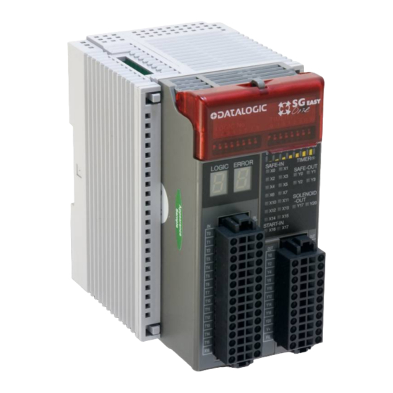
Chapter2 PRODUCT SPECIFICATIONS This chapter describes product specifications of the SG-ONE. Parts Descriptions ⑪ ① ⑩ ENTER LOGIC No. TIMER ⑨ 1 2 3 4 5 6 7 8 0 .1 .5 1 2 5 15 30 ⑧ ⑤ ⑥ .1 .1 .5 .5 1 1 5 5... - Page 12 Dimensions 72.0 109.5 113.5 Locking hole Detail of locking hole...
- Page 13 General specifications Operating conditions Operating temperature (Surrounding air -10 to +55°C (no freezing) temperature) Relative operating humidity 10 to 95% (non-condensing) Storage temperature -40 to +70°C (no freezing) Relative storage humidity 10 to 95% (non-condensing) Pollution degree 2(IEC/EN 60664-1 Degree of protection IP20 IEC/EN 60529 Corrosion immunity Atmosphere be free from corrosive gas...
- Page 14 Note1. Time to shut OFF safety outputs after safety inputs are turned OFF or input monitor error is detected (in case of OFF-delay timer is 0s). If the timer value except 0s, add the selected OFF-delay time to this reaction time. Note2.
- Page 15 Applicable standards Standard Title Functional safety of electrical/electronic/programmable electronic IEC 61508 Part1-7 safety-related systems Safety of Machinery -- Safety-related Parts of Control Systems -- Part 1: EN 954-1 General Design Principles Safety of machinery -- Safety-related parts of control systems -- Part 1: ISO 13849-1 General principles for design Safety of machinery - Functional safety of safety-related electrical,...
- Page 16 Safety performance SG-ONE can be used in a system for category B to 4 and performance level “a” to “e” in accordance with ISO 13849-1: 2006. Average probability of failure on demand (PFD) and Probability of a dangerous failure per hour (PFH) The following table describes PFD and PFH.
- Page 17 Safety input specifications Drive terminal specifications (T0, T1, T2, T3, T4, T5, T6, T7, T10, T11, T12, T13, T14, T15) Rated drive voltage Power supply voltage Minimum drive voltage Power supply voltage – 2.0V Number of drive terminals Note1 Maximum drive current 20mA per port (at 28.8V DC)...
- Page 18 Start input specifications Rated input voltage 24V DC Input ON voltage 15.0V DC to 28.8V DC Input OFF voltage Open or 0V DC to 5.0V DC Number of start input terminals 2 (X16,17) Input current 5mA per port (at rated voltage) Type of input Sink type input (for PNP output), Type 1 (IEC/EN61131-2) Note1...
- Page 19 Safety output specifications Output type Source output (N channel MOSFET) Rated output voltage Power supply voltage Minimum voltage Power supply voltage - 2.0V Number of output terminals 4(Y0, Y1, Y2, Y3) Point 500mA maximum Maximum output current total 1A maximum Leakage current 0.1mA maximum Note1...
- Page 20 Monitor output specifications Output type Source output (N channel MOSFET) Rated output voltage Power supply voltage Minimum output voltage Power supply voltage - 2.0V Number of outputs 11 (Y4, Y5, Y6, Y7, Y10, Y11, Y12, Y13, Y14, Y15, Y16) Point 20mA maximum Maximum output current total...
- Page 21 Solenoid/Lamp output specifications Output type Source output (N channel MOSFET) Rated output voltage Power supply voltage Minimum output voltage Power supply voltage - 2.0V Number of outputs 2 (Y17, Y20) point 500mA maximum Maximum output current total 500mA maximum Leakage current 0.1mA maximum Note1 Allowable Inductive Load...
- Page 22 Indicators (1) Logic LED (green) 0 . 1 . 5 1 2 5 15 30 LOGIC ERROR (2) Error LED (red) TIMER (S) SAFE-IN (3) Timer LED (green) SAFE-OUT (4) Input/Output status LED (orange) -SAFE-IN SOLENOID -OUT -START-IN START-IN -SAFE-OUT (1) Logic LED Indication Status...
- Page 23 (3) Timer LED Indication Status Descriptions No OFF-delay (safety outputs shut off immediately) OFF-delay timer 0.1s OFF-delay timer 0.5s OFF-delay timer 1s OFF-delay timer 2s OFF-delay timer 5s OFF-delay timer 15s OFF-delay timer 30s Each LED Blink Selected timer value (Configuration state) Random ON/Blink Initializing (Initial state)
- Page 24 Specification of configuration switches ENTER LOGIC No. TIMER (S) (1) Logic switch 1 2 3 4 5 6 7 8 0 .1 .5 1 2 5 15 30 (2) Timer switch (3) Enter button (1) Logic switch The logic switch is an 8-digit DIP switch for use in logic configuration. When one of 8 digits is selected, the corresponding logic in the SG-ONE is activated.
- Page 25 Connector specifications ■Input connector T0 T0 X0 X0 T1 T1 X1 X1 T2 T2 X2 X2 T3 T3 X3 X3 T4 T4 X4 X4 T5 T5 X5 X5 T6 T6 X6 X6 T7 T7 X7 X7 T1 T10 0 X1 X10 0 T1 T11 1 X1 X11 1 T1 T12 2...
- Page 26 ■Output connector Y1 Y1 Y0 Y0 Y3 Y3 Y2 Y2 Y5 Y5 Y4 Y4 Y7 Y7 Y6 Y6 Y1 Y11 1 Y1 Y10 0 Y1 Y13 3 Y1 Y12 2 Y1 Y14 4 Y1 Y15 5 Y1 Y17 7 Y1 Y16 6 FE FE FE FE Connector type:...
-
Page 27: Chapter3 Installation And Wiring
Chapter3 INSTALLATION AND WIRING This chapter describes methods and precautions for installing and wiring the SG-ONE. Before starting installation and wiring, be sure to read “SAFETY PRECAUTIONS” in the beginning of this manual and understand the precautions described under WARNING and CAUTION. Warning ●... - Page 28 ● Prevent SG-ONE from falling while moving or transporting the SG-ONE, otherwise damage or malfunction of the SG-ONE may result. ● Prevent metal fragments and pieces of wire from dropping inside the SG-ONE housing. ● Install SG-ONE, so that there is adequate spacing from walls, heat generating bodies, and peripherals, taking into consideration space requirements for maintenance and ventilation.
-
Page 29: Installation Method
Installation method ■ Installation location and direction When the SG-ONE is installed in an enclosure, confirm that installation environments meet the product specifications. Using in environments such as a described below, (over the product specifications) may cause fire hazard, damage, or malfunction. ・SG-ONE should not be exposed to excessive dust, dirt, salt, vibration or shocks. - Page 30 Mount SG-ONE on a vertical plane as shown in Fig.3.2. All other installation directions are not allowed. BNL6 mounting clip Fig. 3.2 Correct installation direction Upwards Sideways Downwards Fig. 3.3 Incorrect installation directions...
- Page 31 ■ Installing on DIN Rails Mount and remove SG-ONE on 35mm-wide DIN rails according to the following instructions. Mounting on DIN rail 1. Fasten DIN rail to a panel using screws. 2. With the top of SG-ONE unit facing up, as shown in Fig. 3.4, insert the groove, on the rear of the unit, and press the unit in the direction of the arrow.
-
Page 32: Wiring Method
Wiring method Note1 SG-ONE has to two kinds of connectors = spring clamp = (optional) and crimp. Note1. For detailed information of Crimp connector, consult Tyco Electronics AMP. ●Applicable connectors and mounting to SG-ONE Applicable connectors Type No. of pole Part No. - Page 33 ● Wiring for spring connector Do not wire the connector while it is connected to the SG-ONE, as this can damage the connector and the SG-ONE. To connect the wire, use a commercially-available screwdriver. It is recommended that you use a dedicated connecting tool to prevent any scratches or damage to the connector housing and spring.
-
Page 35: Chapter4 Basic Operations
Chapter4 BASIC OPERATIONS This chapter describes the basic operations of SG-ONE. Make proper use of the SG-ONE by thoroughly familiarizing yourself with the basic operations and functions. Internal states The SG-ONE operates in five internal states, as shown in Table 4.1. The LED display and output status for each state are shown in Table 4.2. -
Page 36: Turning On The Power
Turning on the power After the SG-ONE is turned on, SG-ONE transitions to the Initial state and checks the internal circuits. SG-ONE changes to the appropriate state (in approximately 6s) according to the result of the internal circuit check. During the Initial state, the LEDs blink to check operation. Logic switch and timer switch are set Logic: “1”... -
Page 37: Logic Configuration
Logic configuration The SG-ONE offers 8 types of logic, and by performing the logic configuration procedure listed below, you can enable the desired logic. The SG-ONE can transition to the Configuration state from the Run or Protection state. Configuration operations are disabled in the Initial and Stop states. Once any logic is configured, it is kept in the SG-ONE even if the power is turned off. - Page 38 3. Confirm the configuration and press the ENTER LOGIC No. TIMER (S) enter button. 1 2 3 4 5 6 7 8 0 .1 .5 1 2 5 15 30 Confirm that the selected logic switch matches the blinking logic LED, and then press the enter 0 .1 .5 1 2 5 15 30 LOGIC ERROR TIMER(S)
-
Page 39: Timer Configuration
Timer configuration SG-ONE has an OFF-delay timer function that retains the safety outputs during the configured time and after that turns OFF the safety outputs. You can use this function to configure stop category "0" or "1". Perform the configuration procedure listed below to configure the OFF-delay timer to one of the following eight settings, using the same procedure as that for configuring the logic: 0, 0.1, 0.5, 1, 2, 5, 15, or 30 s. - Page 40 ENTER 3. Confirm the configuration and press the LOGIC No. TIMER (S) enter button. 1 2 3 4 5 6 7 8 0 .1 .5 1 2 51530 Confirm that the selected timer switch matches 0 .1 .5 1 2 5 15 30 the blinking timer LED, and then press the enter LOGIC ERROR TIMER(S)
-
Page 41: Cancelling The Protection State
Cancelling the Protection state SG-ONE transitions to the Protection state if a failure is detected in an external device or an error is detected in external wiring, such as when different operations are performed between dual channel inputs or two muting inputs, or when the EDM input is OFF while the safety outputs are transitioning from OFF to ON by output control. -
Page 42: Canceling The Stop State
Canceling the Stop state If the SG-ONE detects any wiring errors, abnormalities or internal circuit failure, it changes to the Stop state and locks out operations. The Stop state can be cancelled by the following method. Cancellation by removal of power to SG-ONE The Stop state is cancelled by restart of power to SG-ONE after removing the error factor. -
Page 43: Chapter5 Logic
Chapter5 LOGIC This chapter describes the Logics in the SG-ONE. Make proper use of the SG-ONE by thoroughly familiarizing yourself with the basic operations and function of each Logic. Logic 1: General purpose logic for various apparatuses Overview (Logic 1) This logic is for safety protective measures applicable to production machines, robots, and other apparatuses. - Page 44 Operation example (Logic 1) ・All of emergency stop switches are released. ・Start input is ON ・Safety outputs are ON. ・Movable guard is closed. (All contacts of interlock switches are ON.) ・Safety outputs are ON. ・Emergency stop switch is pressed. ・Safety outputs are OFF. ・Solenoid outputs are ON.
- Page 45 Logic circuit (Logic 1) (Note2) ●Monitor output for safety input ●Monitor output for safety output ●Solenoid output (Note1) Monitor for Monitor for Y0,Y1 safety input 1 safety output 1 & & Y0,Y1 & Monitor for safety input 2 (Note1) Y2,Y3 &...
- Page 46 Functions (Logic 1) ●Safety inputs: X0 to X13 (T0 to T13) X0 to X13 (T0 to T13) function as dual channel direct opening inputs. The combinations of dual channel inputs are as shown below. Incorrect use of these combinations will result in an error. The input monitor error detection time between dual channel inputs is 0.5s. For information about connected control devices, see “SAFETY PRECAUTIONS”...
- Page 47 ●Start inputs: X16 and X17 X16 is used to control the start of the safety outputs as “auto start” which does not use a start switch, or “manual start” which does not detect welding of the start switch. When the start input (X16) is turned ON (the ON state of X16 must be kept over 0.1s) during all devices connected to the safety inputs are in safe state, a start condition is established.
- Page 48 ●State monitor outputs: Y14 to Y16 Y14 to Y16 are monitor outputs for the internal status of the SG-ONE. Y14 turns ON when in the Initial or Stop state. Y15 turns ON in the Initial, Protection or Configuration state. Y16 turns ON when in the Run state. Refer to “Chapter 4 BASIC OPERATION”, or “Chapter 6 TROUBLESHOOTING”, for details of the each state.
- Page 49 Wiring example (Logic 1) In the case of 4 emergency stop switches and 2 safety switches with locks are connected.
- Page 50 Note: In the case of using a spring lock type safety switch for the safety input of SG-ONE, if the solenoid output of SG-ONE is connected to solenoid power terminal of the safety switch directly, the start condition cannot be established due to the safety input stays in the OFF state. In this case, connect the switch or other equipment to solenoid output of SG-ONE, and turn off the operation of the solenoid for lock control.
- Page 51 Timing chart (Logic 1) 1.Case to use the manual start input (X16) 2.Case to use the control start input (X17) OFF delay OFF delay Power ON Safety output ON Power ON Safety output ON time time (Note) (Note) Safety input : X0 Safety input : X0 (Note )...
-
Page 52: Logic 2: General Purpose Logic For No/Nc Contact Inputs
Logic 2: General purpose logic for NO/NC contact inputs Overview (Logic 2) This logic function is for using dual channel NO/NC contact devices as safety protective measures for semiconductor manufacturing machines, food packaging machinery, and other machinery. This logic has 4 dual channel inputs for NO/NC contact devices and 2 dual inputs for direct opening inputs. - Page 53 Operation example (Logic 2) ・Emergency stop switches in the rest position. ・Start input is ON ・Safety outputs are ON. ・Movable guard is closed. (All NO contacts are ON and NC contacts are OFF of Non-contact interlock switches.) 5-11...
- Page 54 ・Emergency stop switch is pressed. ・Safety outputs are ON. ・Safety outputs are OFF. ・Solenoid outputs are ON. ・Movable guard is opened. (NO contact is OFF or NC contact is ON of Non-contact interlock switch.) 5-12...
- Page 55 Logic circuit (logic 2) Safety input 1 Dual Channel NO/NC T0, X0, T1, X1 Safety input 2 Dual Channel NO/NC T2, X2, T3, X3 Safety input 3 Dual Channel NO/NC T4, X4, T5, X5 Safety output 1 Hold & Safety input 4 Hold Dual Channel Self-hold...
- Page 56 Functions (Logic 2) ● Safety inputs: X0 toX13 (T0 to T13) X0 to X7 (T0 to T7) function as dual channel NO/NC inputs. X10 to X13 (T10 to T13) function as dual channel direct opening inputs. The combinations of the dual channel inputs are shown below. Incorrect use of these combinations will result in an error.
- Page 57 ●Start inputs: X16 and X17 X16 is used to control the start of the safety outputs as an “auto start” which does not use the start switch, or “manual start” which does not detect welding of the start switch. When the start input (X16) is turned ON (the ON state of X16 must be received for over 0.1s) during which all devices connected to the safety inputs are in safe state, the start condition is established.
- Page 58 ●State monitor outputs: Y14 to Y16 Y14 to Y16 monitor outputs for the internal status of the SG-ONE. Y14 turns ON during Initial state or Stop state. Y15 turns ON in the Initial state, Protection state or Configuration state. Y16 turns ON while in the Run state. Refer to “Chapter 4 BASIC OPERATION”, or “Chapter 6 TROUBLESHOOTING”, for details of each state.
- Page 59 Wiring example (Logic 2) Incase of 4 non-contact interlock switches, 1 emergency stop switch, and 1 safety switch with lock are connected. 5-17...
- Page 60 When not using the start switch When connecting multiple components in ( Auto start) series Auto start 24V DC When not detecting the welding of start switch ( Manual start) Manual Start 24V DC When detecting the welding of start switch (...
- Page 61 Timing chart (Logic 2) 1.Case to use the manual start input (X16) 2.Case to use the control start input (X17) Off delay Off delay Power ON Safety output ON Power ON Safety output ON time time (Note) Safety input : X0 Safety input : X0 (Note)...
-
Page 62: Logic 3: General Purpose Logic For Machines With Openings
Logic 3: General purpose logic for machines with openings Overview (Logic 3) This logic is for using safety devices with dual channel solid state outputs, such as safety light curtains, for safety protective measures of production machinery, robots, and other machinery. This logic enables the connection of 2 dual channel solid state output (PNP) devices and 4 dual channel direct opening inputs. - Page 63 Operation example (Logic 3) ・Emergency stop switch is released. ・Start input is ON ・Safety outputs are ON. ・Invasions through opening are not detected. ・Safety outputs are ON. ・Emergency stop switch is pressed. ・Safety outputs are OFF. ・Solenoid outputs are ON. ・Invasion through opening is detected.
- Page 64 Logic circuit (Logic 3) Safety input 1 Dual Channel Solid State X0, X1 Safety input 2 Dual Channel Solid State X2, X3 Safety input 3 Dual Channel Direct Opening T4, X4, T5, X5 Safety output 1 Hold & Safety input 4 Hold Dual Channel Self-hold...
- Page 65 Functions (Logic 3) ●Safety inputs: X0 to X13 (T4 to T13) X0 to X3 function as dual channel solid state inputs. These enable the connection of dual channel solid state output (PNP) devices. X4 to X13 (T4 to T13) function as dual channel direct opening inputs. The combinations of dual channel inputs are as shown below.
- Page 66 ●Start inputs: X16 and X17 X16 is used to control the start of safety outputs as an “auto start” which does not use a start switch, or “manual start” which does not detect welding of a start switch. When a start input (X16) is turned ON (the ON state of X16 must be kept over 0.1s) while all devices connected to the safety inputs are in the safe state, the start condition is established.
- Page 67 ●State monitor outputs: Y14 to Y16 Y14 to Y16 are monitoring outputs for the internal status of the SG-ONE. Y14 turns ON when in Initial or Stop state. Y15 turns ON in Initial, Protection or Configuration state. Y16 turns ON in Run state. Refer to “Chapter 4 BASIC OPERATION”, or “Chapter 6 TROUBLESHOOTING”, for details of the each state.
- Page 68 Wiring example (Logic 3) 2 safety light curtains, 2 emergency stop switches, and 2 safety switches with solenoid lock are connected. 5-26...
- Page 69 When not using the start switch When connecting multiple emergency stop switches in ( Auto start) series Auto start 24V DC When not detecting the welding of start switch Manual Start ( Manual start) NOTE: Applicable safety performance is dependent 24V DC upon each system configuration.
- Page 70 Using an DATALOGIC AUTOMATION light curtain SE series as S1, S2 5-28...
- Page 71 Timing chart (Logic 3) 5-29...
-
Page 72: Logic 4: Muting Function Logic For Machines With Openings
Logic 4: Muting function logic for machines with openings Overview (Logic 4) The logic described is for using safety devices with dual channel solid state outputs, such as safety light curtains (Ex. SG2, SG4, SG BODY and SE series), and for devices with output muting signals that enable muting functions that temporarily suspend safety functions of safety devices for safety protective measures of robots, conveyor lines, and other machines. - Page 73 Operation example (Logic 4) Hazardous Area Safety Muting sensors light curtain (Note) Work Objec t Muting lamp (Note) Make sure that the intersection of optical axes is within the hazardous area. ・Emergency stop switch is released. ・Start input is ON ・Safety outputs are ON.
- Page 74 Logic circuit (Logic 4) 5-32...
- Page 75 Function (LOGIC 4) ●Safety inputs: X0, X1, X4, X5, X10 to X13 (T10 to T13) X0, X1, X4, and X5 function as dual channel solid state inputs. These enable connections of dual channel solid state output (PNP) devices. X10 to X13 (T10 to T13) function as dual channel direct opening inputs. The combinations of dual channel inputs are shown below.
- Page 76 ●External device monitor inputs: X14 and X15 (T14 and T15) X14 and X15 (T14 and T15) function as external device monitor inputs. X14 and T14 are used as contact monitors for external devices connected to Y0 and Y1. X15 and T15 are used as contact monitors for external devices connected to Y2 and Y3. Warning Safety check signals (pulses signals) are transmitted from the drive terminals (T14,T15) to diagnose external devices and monitor circuits.
- Page 77 ●Muting input monitor outputs: Y5 and Y7 Y5 and Y7 function as monitoring outputs that output the status of the muting signal devices connected to the SG-ONE. When 24V DC is applied to both terminals of “X2 and X3” or “X6 and X7”, either Y5 or Y7 are turned ON.
- Page 78 Wiring example (Logic 4) 2 safety light curtains and 4 muting sensors and 1 emergency stop switch and 1 safety switch are connected. 5-36...
- Page 79 When connecting multiple emergency stop switches When not using the start switch in series ( Auto start) Auto start 24V DC X 10 X 11 When not detecting the welding of start switch ( Manual start) Manual Start NOTE: Applicable safety performance is dependent 24V DC upon each system configuration.
- Page 80 Timing chart (Logic 4) 5-38...
- Page 81 5-39...
-
Page 82: Logic 5: General Purpose Logic For Devices For Which Sync Time Between Contacts Cannot Be Specified
Logic 5: General purpose logic for devices for which sync time between contacts cannot be specified Overview (Logic 5) The logic described is for safety protective measures applicable to production machinery, robots, and other machinery. This logic enables the connection 6 dual channel dependent inputs. Same as Logic 1, when SG-ONE is in the safe state, all of the safety inputs can receive safety input signals (the contacts of all connected safety devices are ON), safety outputs are turned ON upon input of the start input. - Page 83 Operation example (Logic 5) ・Safety outputs are ON. ・Emergency stop switch is pressed ・Safety outputs are OFF. ・Solenoid outputs are ON. ・Movable guard is opened. (Contacts of 1 of interlock switches are OFF) 5-41...
- Page 84 Logic circuit (Logic 5) Safety input Dual Channel D epende nt T0, X0, T1, X1 Safety input Dual Channel D epende nt T2, X2, T3, X3 Safety input Dual Channel Safety output D epende nt T4, X4, T5, X5 & Safety input ホールド...
- Page 85 Functions (Logic 5) ●Safety inputs: X0 to X13 (T0 to T13) X0 to X13 (T0 to T13) function as dual channel dependent inputs. The combinations of dual channel inputs are shown below. Incorrect use of these combinations will result in an error. The input monitor error detection time between dual channel inputs is infinite.
- Page 86 ●Start inputs: X16 and X17 X16 is used to control the start of the safety outputs as an “auto start” which does not use a start switch, or a “manual start” which does not detect welding of the start switch. When the start input (X16) is turned ON (the ON state of X16 must be on longer than 0.1s) all devices connected to the safety inputs are in safe state, the start condition is established.
- Page 87 Y15 turns ON in Initial, Protection or Configuration state. Y16 turns ON when in Run state. Refer to “Chapter 4 BASIC OPERATION”, or “Chapter 6 TROUBLESHOOTING”, for details of the each state. Warning The monitor outputs are not safety outputs. Do not use these to construct a safety system. ●Solenoid outputs: Y17 and Y20 Y17 and Y20 are outputs for solenoid control that are used for a safety switch with a lock.
- Page 88 Wiring example (Logic 5) Example of 2 emergency stop switches, 2 interlock switches and 2 safety switches with lock are connected. 5-46...
- Page 89 When not using the start switch When connecting multiple emergency stop ( Auto start) switches in series Auto start 24V DC When not detecting the welding of start switch Manual Start ( Manual start) 24V DC NOTE: Applicable safety performance is dependent upon system configuration.
- Page 90 Timing chart (Logic 5) 1.Example of using the manual start input (X16) 2.Example of using the control start input (X17) Off delay Off delay Power ON Safety output ON Safety output ON Power ON time time (Note ) (Note) Safety input : X0 Safety input : X0 (Note )...
-
Page 91: Logic 6: The Logic Applicable For Selection Of An Active Safety Input Device
Logic 6: The logic applicable for selection of an active safety input device Overview (Logic 6) For production machines, robots, and the like, a hazard is generally isolated by a usual protective door (guard); however, when performing maintenance, the machine is operated in the condition that a person is in the danger zone. - Page 92 Operation example (Logic 6) Auto mode (Operating mode) Machine running Machine stop (Safe state) ・Emergency stop switch is pressed ・Safety outputs are OFF. ・Safety outputs are ON. ・Solenoid outputs are ON. ・Movable guard is opened. (Contacts interlock switches are OFF) Teach mode (operating mode) ...
- Page 93 ・Safety outputs are ON. ・Emergency stop switch is pressed ・Safety outputs are OFF. ・Solenoid outputs are ON. ・Release the hand from the enabling switch or grasp the enabling switch strongly 5-51...
- Page 94 Logic circuit (Logic 6) Sel f-hol d functi on ci rcui t 1 Safety input Dual Channel D epende nt & T2, X2, T3, X3 Hold Self-hold function Teach Mode Trigger Mode Safety input Selector T0, X0, X1 >1 Auto Mode Sw itch S el f-hol d functi on ci rcui t 2...
- Page 95 Functions (Logic 6) ● Safety inputs: X0 to X13 (T0 to T13) X0 and X1 (T0) function as mode select inputs. X2 and X3 (T2 and T3) function as dual channel dependent inputs. X4 to X13 (T4 to T13) function as dual channel direct opening inputs. The combinations of inputs are shown below.
- Page 96 ●External device monitoring inputs: X14 and X15 (T14 and T15) X14 and X15 (T14 and T15) function as external device monitoring inputs. X14 and T14 are used as contact monitors for external devices connected to Y0 and Y1. X15 and T15 are used as contact monitors for external devices connected to Y2 and Y3. Warning Safety check signals (pulses signals) are transmitted from the drive terminals (T14, T15) to diagnose external devices and monitor circuits.
- Page 97 ●Safety input monitor outputs: Y4 to Y11 Y4 toY11 function as status monitoring of safety input devices connected to the SG-ONE. Y4 is turned ON only in the case of teach mode is selected by mode select input. Y5 is turned ON while both contacts of the safety device are ON. When 1 or more contacts are OFF, the output is OFF.
- Page 98 Wiring example (Logic 6) Example of 1 enabling switch, 1 selector switch, 2 emergency stop switches, and 2 safety switches with lock (spring lock type) switches are connected. 5-56...
- Page 99 Note: When using a spring lock type safety switch for the safety input of SG-ONE, if the solenoid output of SG-ONE is connected to the solenoid power terminal of the safety switch directly, the start condition cannot be established since the safety input remains in the OFF state. In this case, connect the switch or other equipment to the solenoid output of SG-ONE, and perform the OFF operation of solenoid for lock control.
- Page 100 Timing chart (Logic 6) Teach mode Off delay Off delay Power ON Safety output ON Safety output ON Safety output ON time time Mode select input : X0 Mode select input : X1 Monitor output for X0 and X1 : Y4 (Note 1)...
- Page 101 Auto mode Safety output Off delay Power ON time Mode select input : X0 Mode select input : X1 Monitor output for X0 and X1 : Y4 Safety input : X2,X3 (Note) Safety input : X4 (Note) Safety input : X5 Monitor output for X4 or X5 : Y6 0.1s...5s...
-
Page 102: Logic 7: Partial Stop 1 Logic For Various Machines
Logic 7: Partial stop 1 logic for various machines Overview (Logic 7) The logic described is for safety protective measures of the equipment which has 2 separate devices that are stopped by safety outputs independently, such as semiconductor manufacturing machines, and food packaging machinery. When the 2 devices can not be stopped at the same time or it is not necessary, the 2 safety outputs can be controlled separately. - Page 103 Operation example (Logic 7) Machine running Machine stop <danger zone A> Movable guard A is opened. 5-61...
- Page 104 Machine stop <danger zone A> Movable guard B is opened. Whole machine stops <danger zone A・B> Emergency stop switch is pressed. 5-62...
- Page 105 Logic circuit (Logic7) Self-hold function circuit 1 Safety input Dual Channel Direct Opening Hold T0, X0, T1, X1 Self-hold function Safety input Dual Channel Direct Opening T2, X2, T3, X3 Trigger & Output Function-1 Self-hold function Safety input Dual Channel circuit 2 &...
- Page 106 Functions (Logic 7) ●Safety inputs: X0 to X11 (T0 to T11) X0 to X11 (T0 to T11) function as dual channel direct opening inputs. The combinations of dual channel inputs are shown below. Incorrect use of these combinations will result in an error. The input monitor error detection time between dual channel inputs is 0.5s. For information about connected control devices, see “SAFETY PRECAUTIONS”.
- Page 107 ● Start inputs: X12, X13, X16, and X17 X12 is used to control the start of safety output 1 and 2 as a “control start” which detects welding of the start switch. X12 is the start input for safety input 1. X13 is used to control the start of safety output 1 and 2 as an “auto start”...
- Page 108 ●Safety input monitoring outputs: Y4 to Y10 Y4 toY10 function as status monitoring of safety input devices connected to the SG-ONE. When both contacts of the safety device are ON, the output is ON. When the both contacts are OFF, the output is OFF. If an input monitoring error is detected, a pulse (1Hz) is transmitted.
- Page 109 Wiring example (Logic 7) An example of 3 emergency stop switches and 2 safety switches with lock safety switches connected. 5-67...
- Page 110 When not using the start switch for the When connecting multiple emergency stop switches in start input of partial stop series ( Auto start) Auto start 24V DC When not detecting the welding of start switch for partial stop ...
- Page 111 Timing chart (Logic 7) 1. Example to use manual start input (X13) which does not detect adhesion of the start switch on partial stop. Safety output 2 Off delay Off delay Off delay time time Safety output time Safety output 1 Safety output Power ON all ON...
- Page 112 2. An example to use the control start inputs (X16, X17) that detect adhesion of the start switch on a partial stop. Safety output 2 Safety output 2 Off delay Off delay Off delay Safety output 1 Safety output 1 Safety output time time...
-
Page 113: Logic 8: Partial Stop 2 Logic For Various Machinery
Logic 8: Partial stop 2 logic for various machinery Overview (Logic 8) The logic described is for safety protective measures of equipment which has 2 separate devices that are stopped by safety outputs independently, such as semiconductor manufacturing machines, and food packaging machinery. When 2 devices can not be stopped at the same time or it is not necessary, that 2 safety outputs can be controlled separately. - Page 114 Operation example (Logic 8) ・Machine stop <danger zone B> Movable guard B is opened. ・Machine whole stop <danger zone A・B> Emergency stop switch is pressed or movable guard A is opened. 5-72...
- Page 115 Logic circuit (Logic 8) Self-hold function circuit 1 Safety input Dual Channel Hold Direct Opening T0, X0, T1, X1 Self-hold function Safety input Dual Channel Direct Opening T2, X2, T3, X3 Trigger & Safety output 1 Output Function-1 Self-hold function Safety input &...
- Page 116 Functions (Logic 8) ●Safety inputs: X0 to X11 (T0 to T11) X0 to X11 (T0 to T11) function as dual channel direct opening inputs. The combinations of dual channel inputs are shown below. Incorrect use of these combinations will result in an error. The input monitor error detection time between dual channel inputs is 0.5s. For information about connecting control devices, see “SAFETY PRECAUTIONS”.
- Page 117 ● Start inputs: X12, X13, X16, and X17 X12 is used to control the start of safety outputs 1 and 2 as a “control start” that detects welding of the start switch. X12 is a start input for safety input 1. X13 is used to control the start of safety outputs 1 and 2 as an “auto start”...
- Page 118 ●Safety input monitoring outputs: Y4 to Y10 Y4 toY10 function as status monitoring of safety input devices connected to the SG-ONE. When the both contacts of the safety device are ON, the output is ON. When the both contacts are OFF, the output is OFF.
- Page 119 Wiring example (Logic 8) An example of 3 emergency stop switches and 2 safety switches with lock switches are connected. SG One 5-77...
- Page 120 When connecting multiple emergency stop switches in When not using the start switch for the series start input of partial stop ( Auto start) Auto start 24V DC When not detecting the welding of start switch for partial stop ( Manual start) Manual start 24V DC NOTE: ...
- Page 121 Timing chart (Logic 8) 1. Example to use a manual start input (X13) which is not detected adhesion of the start switch on partial stop. Safety output Safety output Safety output 2 Off delay all ON Off delay all ON Off delay Safety output 2 Power ON...
- Page 122 2. Example of control start inputs (X16, X17) which are detected adhesion of the start switch on a partial stop. Safety output Safety output Safety output 2 Off delay all ON Off delay all ON Off delay time time time Safety output 2 Power ON Safety output 1...
-
Page 123: Logic Functions
Logic functions This section describes the functions of each logic circuit. The logic functions are separated into input, logic operation, and output functions in Table 5-1. Select the appropriate logic after understanding its functionality. Table 5-1 List of logic functions Type Function Symbol... - Page 124 Type Function Symbol Description Reference page AND function This function means logical 5-96 (AND) of multiple inputs. & OR function This function means logical (OR) 5-96 of multiple inputs. >=1 This function means exclusive XOR function 5-97 logical (XOR) of the multiple =2k+1 inputs.
- Page 125 Input functions Dual channel direct opening input This function is for connecting safety devices with dual channel direct opening action mechanisms, such as an emergency stop switch or an interlock switch. As shown in Fig. 5-1, this function is comprised of a dual channel input receive circuit (X ), drive circuit (T ), and function output (I...
- Page 126 Error detection function Input monitoring When an error is detected between dual channel inputs, the SG-ONE changes to the Protection state and displays "1" on the error LED display. The conditions to be detected as input errors are shown below. (1) When the input monitor error detection time (0.5s) is exceeded during 2 input conditions or do not match (namely ON/OFF or OFF/ON).
- Page 127 Dual channel dependent input This function is for connecting safety devices with a dual channel dependent action mechanism, such as an enabling switch. As shown in Fig. 5-3, this function is comprised of a dual channel input receive circuit (X ), a drive circuit (T ), and a functional output (I ).
- Page 128 Error detection function Input monitoring When an error is detected between the dual channel inputs, the SG-ONE changes to the Protection state and displays "1" on the error LED display. The condition to be detected as an input error is shown below. (2) When there is an independent condition change of 1 of the inputs The input LEDs blink and the monitoring output (Y ) outputs pulses (1 Hz), to notify the operator...
- Page 129 Dual channel NO/NC input This function is for connecting safety devices with dual channel NO/NC mechanisms, such as non-contact interlock switches. As shown in Fig. 5-5, this function is comprised of a dual channel input receiving circuit (X ), a drive circuit (T ), and a functional output (I ).
- Page 130 Error detection function Input monitoring and grounding detection When an error is detected between the dual channel inputs, the SG-ONE changes to the Protection state and displays "1" on the error LED display. The conditions to be detected as input errors are shown below.
- Page 131 Dual channel solid state input This function is for connecting a safety device with a dual channel solid state output (PNP output), such as a safety light curtain or a safety laser scanner. As shown in Fig. 5-7, this function is comprised of a dual channel receive circuit (X ) and a functional output (I ).
- Page 132 Error detection function Input monitoring and grounding detection When an error is detected between the dual channel inputs, the SG-ONE changes to the Protection state and displays "1" on the error LED display. The conditions to be detected as input errors are shown below.
- Page 133 Mode select input This function is for connecting devices with a mode select function, such as a selector switch. As shown in Fig. 5-9, this function is comprised of 2 input receiving circuits (X ), 1 drive circuit (T ), and functional output (TEACH, AUTO). Mode selector device TEACH Mode...
- Page 134 Error detection function Input monitoring When an error is detected at the inputs, the SG-ONE changes to the Protection state and displays "1" on the error LED display. The condition to be detected as input error is shown below. (1) When input monitoring error detection time (0.5s) is exceeded while both of the 2 input conditions are ON.
- Page 135 Muting input This function is for connecting a muting sensor with a solid state output (PNP output) or a mechanical contact device such as a limit switch. As shown in Fig. 5-11, this function is comprised of 2 input receiving circuits (X ) and one functional output (MI For muting sensors with a solid state output (PNP) Input device...
- Page 136 Fig. 5-12 Operation timing of the muting input function Error detection function Input monitoring and grounding detection When an error is detected at the inputs, the SG-ONE changes to the Protection state and displays "1" on the error LED display. The conditions to be detected as an input error are shown below. (1) When the input monitor error detection time (3s) is exceeded during the 2 input conditions and they do not match (namely ON/OFF or OFF/ON).
- Page 137 Monitor input This function is for connecting a switch (mechanical contact device) or sensor with a solid state output (PNP output) as the start input. As shown in Fig. 5-13, this function is comprised of 1 receiving circuit (X ) and 1 functional output (I ...
- Page 138 External device monitoring input This function is for monitoring external devices controlled by the SG-ONE. External devices can be diagnosed for errors by connecting a NC contact, such as a contactor or a safety relay. As shown in Fig. 5-15, this function is comprised of an input receiving circuit (X ), drive circuit (T and functional output.
- Page 139 Logic operation function AND function As shown in Fig. 5-16 and 5-17, this function reflects the results of a logic (AND) function processing for multiple inputs (I ) in the function output (O & Fig. 5-16 AND function circuit O FF O FF O FF O FF...
- Page 140 XOR function As shown in Fig. 5-20 and 5-21, this function reflects the results of an exclusive logic (XOR) function processing for multiple inputs (I ) in the function output (O =2k+1 Fig. 5-20 XOR function circuit O FF O FF O FF O FF Fig.
- Page 141 Muting function This function adds muting to the connected safety devices. As shown in Fig. 5-24, this function is comprised of a safety input (I ), a muting input (IM ), and a functional output (O ). The output of the muting input function is connected to the muting input Saf ety Muting Input...
- Page 142 Control start This function confirms operation of the connected start input device. As shown in Fig.5-26, this function is comprised of a functional input (I ) and a functional output (O The start input (I ) ON operation is monitored to determine whether it is performed within the designated control time (0.1 s to 5 s).
- Page 143 Output function Safety output with timer This function is for controlling the safety output. As shown in Fig. 5-28, this function is comprised of a hold input (O ), an EDM input (I ), and a safety output (Y ). The output of this external device monitoring input is connected to the EDM input (I Ex.
- Page 144 Fig. 5-29 Operation timing of safety output with timer Fig. 5-30 Operation timing when EDM input error occurs Error detection function EDM input monitoring When the following condition is satisfied, the SG-ONE changes to the Protection state and displays "1" in the error LED display. (1) When the EDM input does not turn ON within the EDM monitoring time (1 s) after the hold input turns ON The input LEDs blink and the monitor output (Y...
-
Page 145: Chapter6 Trouble Shooting
Chapter6 TROUBLE SHOOTING This chapter describes how to determine the cause of a failure or error that occurs with the SG-ONE or connected device, and the measures to take to solve the problem. Error descriptions and troubleshooting The SG-ONE uses advanced diagnostic functions to detect any problems within the SG-ONE and its peripheral devices, thereby ensuring the safety performance of the entire system. - Page 146 Muting lamp error Broken wire of Check functionality and (broken wire) muting lamp wiring of the muting (For logic 4 only) wiring lamp. Broken wire of Check the operation of Muting lamp the muting lamp. Fault in power supply The voltage of Check voltage of the internal power...
-
Page 147: Chapter7 Appendix
Chapter7 APPENDIX Minimum Distance The minimum distance is the distance required to minimize the risk of contact with the hazard in the danger zone. Be sure to maintain a sufficient minimum distance while taking into consideration the stopping time of the entire system, including the reaction time of the SG-ONE and the reaction time of any connected devices. - Page 148 Example in which the direction of entry is perpendicular to the safety light curtain Protective Area Limit Danger Zone Access When the size of the minimum detected object is 40 (mm) or smaller Use the following formula to calculate the minimum distance. S=K×(Tc+T1+T2)+C Tc=t1+t2 If using the SG-ONE and a safety light curtain, the following parameters are used for the above...
- Page 149 Example in which the direction of entry is horizontal to the safety light curtain Protective Area Limit Access Danger Zone Use the following formula to calculate the minimum distance (distance to the farthest optical axis). S=K×(Tc+T1+T2)+C Tc=t1+t2 C=(1200-0.4×H) K=1600 (mm/s) t1=0.04 (s) t2=0 (s), 0.1 (s), 0.5 (s), 1 (s), 2 (s), 5 (s), 15 (s), 30 (s) T1(s) (Check the specifications of the safety light curtain.)
- Page 150 Example in which the direction of entry is at an angle to the safety light curtain Protective Area Limit Danger Zone Access 侵入方向 The angle of entry is set within a range of 5°≤β≤85°. At β>30°, the direction of entry is calculated as being perpendicular. At β<30°, the direction of entry is calculated as being horizontal.
- Page 151 ■ For ANSI B11.19 Use the following formula to calculate the minimum distance. S=K×(Ts+Tc+Tr+Tbm)+Dpf Tr=t1+t2+T1 Parameters S: Minimum distance (mm) K: Speed of the detected object or arm or leg entering the danger zone (mm/s) However, the speed of entry K is not defined by ANSI B11.19. Take into consideration various factors such as the physical ability of the operator.
-
Page 152: Maintenance And Inspection
Maintenance and Inspection Warning To ensure safety, use the SG-ONE after performing inspections described below and confirming that the entire safety system incorporating the SG-ONE is operating normally. The following checklist contains only the minimum items for use of the SG-ONE. Depending on the machinery on which the SG-ONE is installed and the regulations that apply in the country or region where the SG-ONE is used, additional inspection items may be required. - Page 153 Type number Item Type number Module SG-ONE-T4-8C Accessories Item Quantity Input connector Output connector Configuration tool Marking tie Instruction sheet 1 for each (English/Italian) CD wiyh instruction manual and other documents...
Need help?
Do you have a question about the SG EASY One and is the answer not in the manual?
Questions and answers