
Related Manuals for BraunAbility PIN AND PIN HEAVY-DUTY


Summary of Contents for BraunAbility PIN AND PIN HEAVY-DUTY
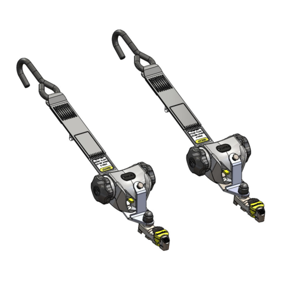
- Page 1 PIN AND PIN HEAVY-DUTY WHEELCHAIR TIE-DOWN User Manual Applicable to products P-RQE10MJ, P-RQE16MK, P-SQE10MJ UI12354 Instructions for fitting and use...
- Page 2 If you have any questions about your equipment, please contact us. Once again, thank you for placing your confidence in our products! Safe vehicle adaptation solutions For your safety BraunAbility products are designed and tested according to current directives and standards.
- Page 3 PIN and PIN Heavy Duty wheelchair tie-down Safety information Limitation of use General guidance Before installing and using the wheelchair restraint kits Fit and use Fit and use - classic - front tie-down - Solo anchorage Fit and use - classic - rear - Solo anchorage Fit and use - classic - front - rail floor Fit and use - classic - rear - rail floor Fit and use - heavy duty - front - rail floor...
-
Page 4: Safety Information
PIN and PIN Heavy Duty wheelchair tie-down Safety information Limitation of use The development of BraunAbility kits is a continuous process. Applications are added on a regular basis. For more details contact BraunAbility or look on the BraunAbility website. - Page 5 PIN and PIN Heavy Duty wheelchair tie-down P-RQE10MJ P-RQE16MK P-SQE10MJ...
-
Page 6: General Guidance
PIN and PIN Heavy Duty wheelchair tie-down General guidance • Wheelchair Accessories that have not been approved by the Wheelchair Manufacturer must be removed from the wheelchair and secured in the vehicle during transport to reduce the potential for injury. Refer to ‘Instructions For Use in Transport’ provided with the wheelchair or contact wheelchair manufacturer for further guidance. - Page 7 Anchorages should not be installed into unsound materials such as corroded metal, wood, plastic and fibreglass panels, without additional and suitable reinforcement. • The equipment has been tested in a configuration recommended by BraunAbility and any deviation from the recommendations here is the responsibility of the installer/user.
- Page 8 PIN and PIN Heavy Duty wheelchair tie-down Before installing the wheelchair restraint kits • Ensure that the wheelchair is correctly maintained and that the settings of any adjustable parts are made according to ‘Instructions for Use in Transport’. • Whenever possible remove any items of luggage etc that may be attached to the wheelchair and secure or store separately during transport in order to reduce the potential for injury to other passengers traveling in the vehicle.
- Page 9 PIN and PIN Heavy Duty wheelchair tie-down • Wheelchair users, their caregivers and family are advised to check vehicle specifications to ensure that sufficient floor space is available to accommodate the wheelchair and tie-down system. These distances are based upon the desire to maintain clear zones for potential head excursions of occupants provided with both upper and lower torso restraints.
- Page 10 PIN and PIN Heavy Duty wheelchair tie-down Fit and use PIN classic wheelchair tie-down Solo anchor - front The Solo floor anchors will have been installed in the vehicle in accordance Removing the self-retracting front with their own and the vehicle converter’s instruction. Position the wheelchair tie-down within the vehicle as required.
- Page 11 PIN and PIN Heavy Duty wheelchair tie-down Figure 4 Figure 1 Figure 5 Wheelchair reference plane B - rotate 90° Front securement points 40° 60° 25° 25° 300mm A - slide on (12in) SIDE VIEW FRONT VIEW Figure 2 Figure 3 Figure 6...
- Page 12 PIN and PIN Heavy Duty wheelchair tie-down Fit and use PIN classic wheelchair tie-down Solo anchor - rear Removing the self-retracting rear Place the retractor behind the wheelchair. It is acceptable to use the restraint tie-down either for left-hand or right-hand use. Ensure the wheelchair restraints are fitted with the J-hook gates facing outwards (Fig.
- Page 13 PIN and PIN Heavy Duty wheelchair tie-down Figure 7 Figure 1 Figure 3 Figure 8 Wheelchair reference plane B - rotate 90° Rear securement points 30° 45° 300mm 10° (12in) 10° REAR VIEW SIDE VIEW NOTE Note that angles indicated are obtained by projecting the angle of each tie-down strap onto a vertical plane parallel to the wheelchair reference plane (side view) or onto a vertical A - slide on plane that is perpendicular to the wheelchair reference plane (rear view).
- Page 14 PIN and PIN Heavy Duty wheelchair tie-down Fit and use PIN classic wheelchair tie-down Rail floor - front The rail will have been installed in the vehicle in accordance with our own and Removing the self-retracting front the vehicle converter’s instruction. Position the wheelchair within the vehicle tie-down as required.
- Page 15 PIN and PIN Heavy Duty wheelchair tie-down Figure 4 Figure 10 Figure 5 Wheelchair reference plane Front securement points 40° 60° 25° 25° 300mm (12in) SIDE VIEW FRONT VIEW Figure 6 Figure 11...
- Page 16 PIN and PIN Heavy Duty wheelchair tie-down Fit and use PIN classic wheelchair tie-down Rail floor - rear Install each rear Retractor by aligning the ATF (aluminum track fitting) feet Removing the self-retracting rear with the cut out sections of the rail. Press down on the ribbed part of the ATF tie-down (Fig.
- Page 17 PIN and PIN Heavy Duty wheelchair tie-down Figure 7 Figure 10 Figure 8 Wheelchair reference plane Rear securement points 30° 45° 300mm 10° (12in) 10° REAR VIEW SIDE VIEW NOTE Note that angles indicated are obtained by projecting the angle of each tie-down strap onto a vertical plane parallel to the wheelchair reference plane (side view) or onto a vertical plane that is perpendicular to the wheelchair reference plane (rear view).
- Page 18 PIN and PIN Heavy Duty wheelchair tie-down Fit and use PIN heavy duty wheelchair tie-down Rail floor - front The rail will have been installed in the vehicle in accordance with our own and Removing the self-retracting front the vehicle converter’s instruction. Position the wheelchair within the vehicle tie-down as required.
- Page 19 PIN and PIN Heavy Duty wheelchair tie-down Figure 4 Figure 12 Wheelchair reference plane Front securement points 40° 60° 25° 25° 300mm (12in) SIDE VIEW FRONT VIEW Figure 6 Figure 11 Figure 13...
- Page 20 PIN and PIN Heavy Duty wheelchair tie-down Fit and use PIN heavy duty wheelchair tie-down Rail floor - rear Removing the self-retracting Install each rear retractor by aligning the ATF (aluminum track fitting) feet with the cut out sections of the rail. Press down on the ribbed part of the ATF rear tie-down (Fig.
- Page 21 PIN and PIN Heavy Duty wheelchair tie-down Figure 3 Figure 8 Figure 12 Figure 14 Wheelchair reference plane Rear securement points 30° 45° 300mm 10° (12in) 10° REAR VIEW SIDE VIEW NOTE Note that angles indicated are obtained by projecting the angle of each tie-down strap onto a vertical plane parallel to the wheelchair reference plane (side view) or onto a vertical Figure 10 plane that is perpendicular to the wheelchair reference plane (rear view).
- Page 22 • If the vehicle is involved in an accident when any restraints are deployed, remove them from service and replace immediately. If in doubt please contact BraunAbility.
-
Page 23: Declaration Of Conformity
Declaration of conformity Manufacturer / Conforms to following directives standards and regulations / BraunAbility UK Ltd Unwin House 214/2013/ EU Paragraphs 2.3.1 and 2.3.2 The Horseshoe Coat Road ISO 10542:2012 Martock, Somerset, TA12 6EY, RESNA WC-4 2012 Section 18 2001/85/EC R.107.06... -
Page 24: Warranty
BraunAbility products when used in conjunction with such jointly tested systems. For further details on specific applications please contact the Sales Office. In other situations, using BraunAbility products, for which BraunAbility has not participated in a joint test program, a limited BraunAbility warranty will apply. - Page 25 Accredited by URS as testing laboratory in accordance with ISO/IEC 17025:2005 Quality system certified in accordance with ISO 9001:2008 Illustrations, descriptions and specifications in the user manual are based on current product information. BraunAbility UK Ltd reserves the right to make alterations without previous notice. © 2020 BraunAbility UK Ltd...
- Page 26 BraunAbility UK Ltd Unwin House Toll Free: (800) 488-0359 The Horseshoe, Coat Road Email: questions@braunability.com Martock, Somerset, TA12 6EY, www.braunability.eu...