
Related Manuals for Dunlop L.CRA.17D.C.M


Summary of Contents for Dunlop L.CRA.17D.C.M
- Page 1 INSTA LLATI ON MANUAL L.CRA.17D.C.M and L.CRA.17D.4.C.M DRW, DOUBLE REAR WHEEL DRIVE AND 4X4 VOLKSWAGEN CRAFTER (2017 ONWARDS) MAN TGE (2017 ONWARDS) DUN LO P SYST E M S.N L...
- Page 2 2 | INSTALLATION MANUAL | AUXILIARY AIR SUSPENSION | VOLKSWAGEN CRAFTER DRW AND 4X4 / MAN TGE DRW AND 4X4 FEB 2021...
-
Page 3: Table Of Contents
Contents Foreword Introduction Very important notes Overview Instructions for installation Recommended Tightening Torque Preparation Bump Stop Removal and fitting of Upper Bracket Attachment of the LED-Lights Sensor Attachment of the Lower Bracket and the Bellows Fitting of Inflator Console Tube Connection and Disconnection, Cutting and Routing Bellow Inflation Bellow Alignment 5.10 Maintenance... -
Page 4: Foreword
1 Foreword This manual provides instructions for the installation of an auxiliary air suspension kit, developed specifically for the Volkswagen Crafter DRW / 4x4 double tires as also the MAN TGE DRW / 4x4 double tires (2017- onwards). To ensure correct installation of the kit, it is strongly recommend that these instructions are read thoroughly before commencing any installati- on work. -
Page 5: Introduction
2 Introduction THANK YOU FOR CHOOSING AN AUXILIARY AIR SUSPENSION KIT FROM THE RANGE OFFERED BY DSC NEDERLAND AUXILIARY AIR SUSPENSION IS FITTED IN TANDEM WITH THE STANDARD STEEL SPRINGS OF THE VEHICLE SUSPENSION, AND PROVIDES ENHAN- CEMENTS IN TERMS OF BOTH THE STABILITY OF THE VEHICLE AND THE COMFORT OF THE PASSENGERS…... -
Page 6: Very Important Notes
3 Very important notes IMPORTANT: Gross Vehicle Weight (GVW) Air assist kits are not in themselves designed to increase the gross vehicle weight (GVW) rating of a vehicle. They do not legally allow for carriage of a load greater than the carrying capacity stated on the data plate of the vehicle. -
Page 7: Overview
4 Overview THE COMPLETE BELLOW AND BRACKET ASSEMBLY IS SHOWN OF THE RIGHT SIDE BY THE DIAGRAM BELOW. NUMBER PART NUMBER DESCRIPTION QUANTITY NOT IN THE ASS EM BLY D RAW ING 81.13.00.1.01.01* Top plate Left • Tie wraps 81.13.00.1.02.01 Top plate Right •... -
Page 8: Instructions For Installation
5 Instructions for installation IMPORTANT: Preparation and Precaution Before beginning installation, ensure that you have sufficient clearance between the axle and the chassis. Use a jack if necessary. Install at one side of the vehicle at a time. Pay attention to your safety at all times during installation - always use axle stands to support the vehicle! The position of the axle stands should be under the chassis NOT under the axle! 5.1 R ECO M M E N DED T IG H T ENING TO RQUE... -
Page 9: Bump Stop Removal And Fitting Of Upper Bracket
5 . 3 BU M P STO P R EMOVAL AND FIT T ING O F UPP ER BRAC KET Remove the two bump stops (Figure 1 and 2). Drill out the blind rivet (Figure 3) of the LED head light sensor. Use a drill of 5 mm (Not all models will have this sensor). -
Page 10: Fitting Of Inflator Console
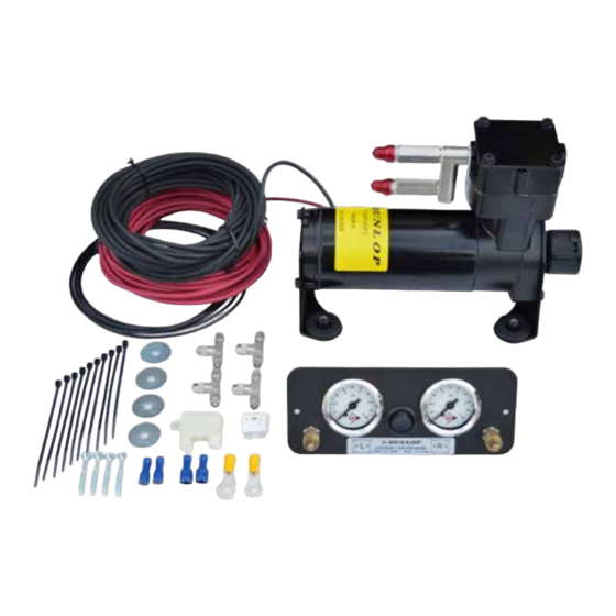
5 . 6 F I T TI N G O F IN FLATO R CON SO LE Your kit is supplied with one of these inflator options: OP T IO N VALV ES Two valves and a small bracket OP T IO N MANO Two valves and two independent 10-bar pressure gauges ( W I TH O U T CO N SO LE) - Page 11 Mount the console in a position of your choice whereby it is firmly fixed, has some protection from the environment (particularly important for the console with gauges) and is easily accessible. Suggested possible locations include. ‘STA N DA RD ’ CO NS O LE •...
-
Page 12: Tube Connection And Disconnection, Cutting And Routing
5 . 7 TU B E CO N NECT IO N AND DIS CO N NEC TIO N, C UTTI NG AND ROU TING CO N N EC T I O N AND DIS CO NNECT IO N Tubes are connected as shown by the diagrams below: A. -
Page 13: Bellow Inflation
RO U TI N G Study the underside of the vehicle and decide how to route each branch of the air circuit. • To minimise the risk of chafing, avoid running tubing over metal edges as much as possible • Avoid close proximity to heat sources such as the exhaust assembly •... -
Page 14: Bellow Alignment
5 .9 S PR I N G ALI GN MEN T With the vehicle standing at the desired ride height, ensure that the springs are correctly aligned as illustrated above and then tighten the bolts to secure the bellow to both the upper and the lower mounting brackets. -
Page 15: Check List
5 .1 1 C H EC K LI ST Before driving the vehicle following completion of installation of the auxiliary air suspension system, please check: All bolts tightened to the recommended torque (Page 7)? Air springs set in alignment (Section 5.9)? Enough free space around the air springs to avoid wearing? All metal parts wax coated (Section 5.10)? Manufacturer’s declaration form completed and a copy returned? -
Page 16: Installation Pictures
6 INSTALLATION PICTURES ^ L.C RA .1 7D.C .M - STANDAR D ^ L .CRA.17D.4.C .M - 4 X4 16 | INSTALLATION MANUAL | AUXILIARY AIR SUSPENSION | VOLKSWAGEN CRAFTER DRW AND 4X4 / MAN TGE DRW AND 4X4 FEB 2021... - Page 17 17 | INSTALLATION MANUAL | AUXILIARY AIR SUSPENSION | VOLKSWAGEN CRAFTER DRW AND 4X4 / MAN TGE DRW AND 4X4 FEB 2021...
- Page 18 Spring out of alignment Spring in alignment mounting plate axes mounting plates parallel offset and coaxial CAUTION! - Before fully tightening the bolts that secure the air spring to the upper and lower brackets, set the vehicle at ride height (spring height approximately 13, 14 cm) and ensure that the springs are correctly aligned. 18 | INSTALLATION MANUAL | AUXILIARY AIR SUSPENSION | VOLKSWAGEN CRAFTER DRW AND 4X4 / MAN TGE DRW AND 4X4 FEB 2021...
-
Page 19: Epilogue
7 EPILOGUE DSC Nederland hopes that you enjoy the benefits that your DUNLOP air suspension system will provide for you. To ensure optimal performance, we advise that you have your system checked frequently by qualified personnel. As recommended in the fitting instructions, it is important to coat all the steel parts with a protec- tive substance such as body wax IMPORTANT: Manufacturer’s Declaration Form... - Page 20 DSC Nederland B.V. Het Wegdam 22 7496 CA Hengevelde Nederland +31 (0)547 333 065 +31 (0)547 333 068 DUNLOP and the Flying D device are trademarks of Sumitomo Rubber Group and are used under info@dunlopsystems.nl license by DSC Nederland B.V. W www.dunlopsystems.nl...
Need help?
Do you have a question about the L.CRA.17D.C.M and is the answer not in the manual?
Questions and answers