Advertisement
Table of Contents
- 1 Table of Contents
- 2 Contents
- 3 Caution
- 4 Necessary Repairing Tools
- 5 Tightening Torque Specifications
- 6 Repair
- 7 Window Frame Section
- 8 Disassembling/ Assembling of Window Frame
- 9 DC Jack Cover
- 10 Disassembling/ Assembling of DC Jack Cover
- 11 Housing Section
- 12 Disassembling/ Assembling of Battery Terminal
- 13 Disassembling/ Assembling of Main Housing
- 14 Keypad (Switch) Section
- 15 Replacement
- Download this manual
Advertisement
Table of Contents

Related Manuals for Makita SK105D


Summary of Contents for Makita SK105D
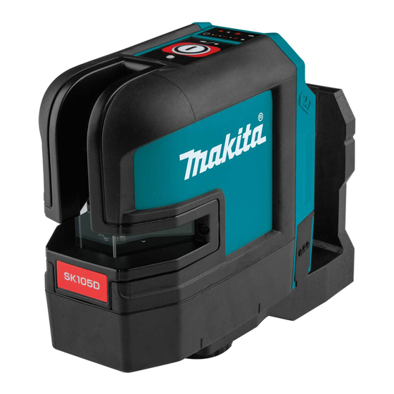
- Page 1 OFFICIAL USE For ASC CORDLESS CROSS LINE LASER SK105D/ SK105GD SK106D/ SK106GD REPAIR MANUAL December 2019 Ver.1...
- Page 2 CONTENTS CONTENTS ....................................2 CAUTION ....................................3 NECESSARY REPAIRING TOOLS ............................3 TIGHTENING TORQUE SPECIFICATIONS ..........................3 REPAIR ......................................4 Window frame section ................................. 4 5-1-1 Disassembling/ Assembling of Window frame ......................4 DC Jack cover ..................................5 5-2-1 Disassembling/ Assembling of DC Jack cover ......................5 Housing section ..................................
- Page 3 CAUTION Repair the machine in accordance with "Instruction manual" or "Safety instructions". Follow the instructions described below in advance before repairing: Wear ESD Anti-static electronics gloves. In order to avoid wrong reassembly, draw or write down where and how the parts are assembled, and what the parts are. It is also recommended to have boxes ready to keep disassembled parts by group.
- Page 4 REPAIR Window frame section 5-1-1 Disassembling/ Assembling of Window frame Fig. 1 Remove Front label indicated by the red circle, then remove Screw. Remove the adhesive residue and stick a new Front label when assembling. Fig. 2 Remove 2x8 Tapping screws (4 pcs) with T6 screwdriver.
- Page 5 DC Jack cover 5-2-1 Disassembling/ Assembling of DC Jack cover Fig. 4 Pull out DC Jack cover in direction of arrow. Note DC Jack cover is not glued with adhesive, and therefore, remove it manually. Insert DC Jack cover into the groove of Housing when assembling.
- Page 6 5-3-2 Disassembling/ Assembling of Main housing Fig. 7 Remove Base labels (2 pcs) because there are Screws under them. Remove the adhesive residue and stick new Labels when assembling. Fig. 8 Remove 2.6x20 Tapping screws (3 pcs.) with T8 screwdriver. Tighten them with a torque of 0.4 N∙m when assembling.
- Page 7 Fig. 10 When assembling Main housing, put Keypad cable (shown with green) in place as shown in the figure. Keypad (Switch) section 5-4-1 Replacement Fig. 11 Disconnect Keypad cable from Control board beforehand, and then replace Keypad (switch). Keypad (Switch) is peeled off because it is glued with an adhesive.
Need help?
Do you have a question about the SK105D and is the answer not in the manual?
Questions and answers
كيف يمكنني تحديد اماكن الاسلاك الرقيقة اذا تمت ازالتها كلها (الاسلاك المعدنية الرقيقة المعزولة)