
Related Manuals for Tektronix Keithley 6517B/E


Summary of Contents for Tektronix Keithley 6517B/E
- Page 1 tek.com/keithley Model 6517B Electrometer User's Manual 6517B-900-01 Rev. B August 2022 *P6517B-900-01B* 6517B-900-01B...
- Page 2 Model 6517B Electrometer User's Manual...
- Page 3 © 2022, Keithley Instruments, LLC Cleveland, Ohio, U.S.A. All rights reserved. Any unauthorized reproduction, photocopy, or use of the information herein, in whole or in part, without the prior written approval of Keithley Instruments, LLC, is strictly prohibited. These are the original instructions in English. All Keithley Instruments product names are trademarks or registered trademarks of Keithley Instruments, LLC.
- Page 4 Safety precautions The following safety precautions should be observed before using this product and any associated instrumentation. Although some instruments and accessories would normally be used with nonhazardous voltages, there are situations where hazardous conditions may be present. This product is intended for use by personnel who recognize shock hazards and are familiar with the safety precautions required to avoid possible injury.
- Page 5 For safety, instruments and accessories must be used in accordance with the operating instructions. If the instruments or accessories are used in a manner not specified in the operating instructions, the protection provided by the equipment may be impaired. Do not exceed the maximum signal levels of the instruments and accessories. Maximum signal levels are defined in the specifications and operating information and shown on the instrument panels, test fixture panels, and switching cards.
-
Page 6: Table Of Contents
Table of contents Introduction ....................... 1-1 Welcome ..........................1-1 Capabilities and features overview ..................1-1 Extended warranty ....................... 1-2 Contact information ......................1-2 General ratings ........................1-2 Unpacking and inspection for damage ................. 1-3 Returning instrument for service ..................1-3 Shipment contents ....................... - Page 7 Table of contents Model 6517B Electrometer User's Manual Input protection ......................... 3-3 High-resistance meter connections ..................3-4 Voltage source output connections ..................3-5 Low-noise input cables......................3-6 Shielding and guarding ......................3-6 Noise shield..........................3-7 Guard shield ..........................3-8 Safety shield ..........................3-9 Floating circuits ........................
- Page 8 Model 6517B Electrometer User's Manual Table of contents Maintenance ......................5-1 Introduction .......................... 5-1 Line fuse ..........................5-1 Line fuse replacement ....................... 5-2 Change the line voltage ....................... 5-3 Upgrading the firmware ......................5-3 Status and error messages ....................5-3...
-
Page 9: Introduction
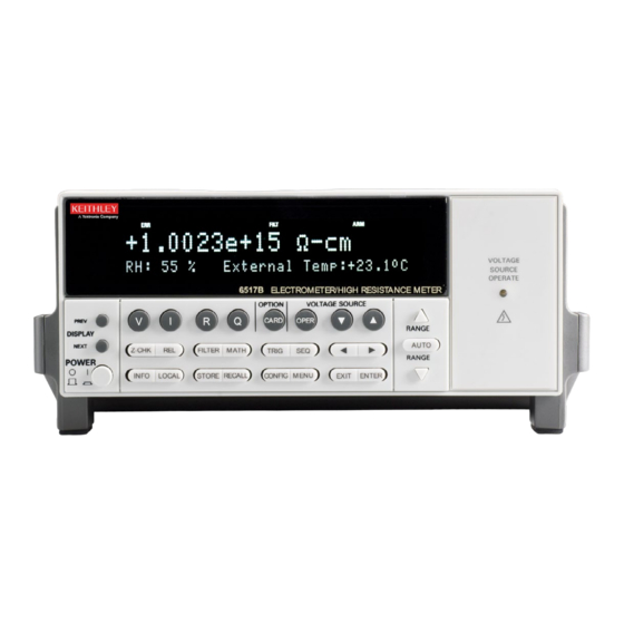
Section 1 Introduction In this section: Welcome ...................1-1 Capabilities and features overview ...........1-1 Extended warranty ..............1-2 Contact information ..............1-2 General ratings .................1-2 Unpacking and inspection for damage ........1-3 Returning instrument for service ..........1-3 Shipment contents ..............1-3 Options and accessories ............1-3 Welcome The 6½-digit 6517B Electrometer/High Resistance Meter offers 1 fA sensitivity and >... -
Page 10: Extended Warranty
If you have any questions after you review the information in this documentation, please contact your local Keithley Instruments office, sales partner, or distributor. You can also call the Tektronix corporate headquarters (toll-free inside the U.S. and Canada only) at 1-800-833-9200. For worldwide contact numbers, visit tek.com/en/contact-tek. -
Page 11: Unpacking And Inspection For Damage
Model 6517B Electrometer User's Manual Section 1: Introduction Unpacking and inspection for damage The 6517B was carefully inspected electrically and mechanically before shipment. There may be a protective film over the display lens, which can be removed. Before removing the 6517B from the antistatic bag, observe the following handling precautions: •... -
Page 12: Getting Started
Section 2 Getting started In this section: Introduction ................2-1 Front-panel overview ..............2-1 Rear-panel overview ..............2-4 Power the instrument on or off ..........2-6 Using the menus ...............2-9 Menu ..................2-9 Display ..................2-14 Saving setups .................2-20 Reset the instrument ...............2-21 Introduction This section provides power-up information and descriptions of the controls and components of the 6517B. - Page 13 Section 2: Getting started Model 6517B Electrometer User's Manual ANNUNCIATORS EDIT: Editing voltage source values. ERR: Questionable reading. REM: In remote. TALK: Addressed to talk. LSTN: Addressed to listen. SRQ: Service Request. REL: Displayed reading has relative offset applied. FILT: Digital filter enabled. MATH: Math calculation enabled.
- Page 14 Model 6517B Electrometer User's Manual Section 2: Getting started OPERATION KEYS Z-CHK: Enables or disables zero check. You must enable zero check before changing functions. REL: Enables or disables a relative offset reading. FILTER: Displays the digital filter status for the present function and toggles the filter. MATH: Displays math calculation and toggles math if configured.
-
Page 15: Rear-Panel Overview
Section 2: Getting started Model 6517B Electrometer User's Manual Rear-panel overview The rear panel of the 6517B is shown in the following figure. The descriptions of the rear-panel components follow the figure. Figure 2: Model 6517B rear panel INPUT CONNECTOR Unguarded configuration: Disable GUARD for current, resistance, charge, and unguarded voltage measurements. - Page 16 Model 6517B Electrometer User's Manual Section 2: Getting started COMMON Connector that is internally connected to INPUT low. Chassis ground Connects the chassis to ground through the power line cord. For use with a noise shield, refer to Noise shield (on page 3-7).
-
Page 17: Power The Instrument On Or Off
Section 2: Getting started Model 6517B Electrometer User's Manual 13 TRIGGER LINK An 8-pin micro DIN connector for sending and receiving trigger pulses to and from other instruments. 14 V-SOURCE HI and LO Safety banana jacks for the voltage source. Rated at 1000 V maximum. 15 OPTION SLOT A slot for option cards, such as the Model 6521 or Model 6522 scanner card. -
Page 18: Power-Up Sequence
Model 6517B Electrometer User's Manual Section 2: Getting started Power-up sequence When the 6517B is powered up, it performs the following tests: • Self-tests on its EEPROM and RAM • Checksum tests on data stored in nonvolatile memory If a failure is detected, the instrument momentarily displays an error message and the ERR annunciator turns on. - Page 19 Section 2: Getting started Model 6517B Electrometer User's Manual The error messages that may be displayed during the power-up sequence are summarized in the following table. These are shown when one of the checksum tests fails. Message Description Action Error −314 Save/recall memory lost Instrument setup is reset to bench defaults, which are stored in EEPROM.
-
Page 20: Using The Menus
Model 6517B Electrometer User's Manual Section 2: Getting started Using the menus The 6517B has main and configure menus. The main menu accesses items for which there are no dedicated keys. The configure menus set up measurement functions and other instrument operations. To access the main menu, press the MENU key. -
Page 21: Savesetup
Section 2: Getting started Model 6517B Electrometer User's Manual SAVESETUP The SAVESETUP option of the main menu is used for the following operations: • To save the present instrument configuration in nonvolatile memory • To restore the instrument to a previously saved instrument configuration •... -
Page 22: Communication
Model 6517B Electrometer User's Manual Section 2: Getting started COMMUNICATION The COMMUNICATION menu option allows you to select and configure the GPIB or RS-232 bus. Refer to the following section in the Model Menu item Description 6517B Electrometer Reference Manual Options to select and configure GPIB operations: Remote operations GPIB... -
Page 23: Limits
Section 2: Getting started Model 6517B Electrometer User's Manual LIMITS The LIMITS menu sets and controls the limit values that determine the PASS or FAIL and HI or LO status of subsequent measurements and sets the digital output patterns that signify passing or failing limit checks. - Page 24 Model 6517B Electrometer User's Manual Section 2: Getting started • Configures timestamp. • Chooses the characters displayed for decimal and select measurement units. • Sets the real-time clock. Menu item Description Refer to: “Digital I/O” in the Model Sets up the digital output lines: DIGOUT 6517B Electrometer ...
-
Page 25: Display
Section 2: Getting started Model 6517B Electrometer User's Manual Display The display of the 6517B provides measurement readings with their units and types of measurements. It also displays informational messages, such as menu headings and selections. The top of the display has annunciators that indicate states of operation. The top line of the display shows readings and units. -
Page 26: Messages
Model 6517B Electrometer User's Manual Section 2: Getting started To change how the readings are displayed: 1. Press the MENU key. 2. Select GENERAL. 3. Select DISPLAY. 4. Select NUMERIC-FORMAT. 5. To select: Engineering units: Select ENGR. Scientific notation: Select SCIENTIFIC. ... -
Page 27: Measurement Function Displays
Section 2: Getting started Model 6517B Electrometer User's Manual To display instrument information: 1. Press the MENU key. 2. Select the GENERAL menu. 3. Select SERIAL #. 4. Press the ENTER key. Measurement function displays Each measurement function has its own set of displays, shown in the bottom line of the front-panel display. - Page 28 Model 6517B Electrometer User's Manual Section 2: Getting started To set the clock: 1. On the front panel, press the MENU key. 2. Select the GENERAL menu. 3. Select CLOCK. 4. Select DATE. 5. Use the ◄ and ► cursor keys and the RANGE keys to set the date. The day of the week (such as Sun or Mon) is automatically calculated and displayed for the date.
- Page 29 Section 2: Getting started Model 6517B Electrometer User's Manual Zero-centered bar graph The zero-centered bar graph is a graphical representation of a reading with positive and negative limits, as shown in the figure below. The limits are expressed in a user-selectable percentage of range.
- Page 30 Model 6517B Electrometer User's Manual Section 2: Getting started Maximum and minimum The maximum and minimum display shows the maximum and minimum readings since the display was entered. Math functions are not applied to the minimum and maximum. An example of the display is shown in the following figure.
-
Page 31: Saving Setups
Section 2: Getting started Model 6517B Electrometer User's Manual To change the temperature units: 1. Press the MENU key. 2. Select the GENERAL menu. Press the ENTER key. 3. Select the DISPLAY menu. Press the ENTER key. 4. Select TEMP-UNITS. Press the ENTER key. 5. -
Page 32: Reset The Instrument
Model 6517B Electrometer User's Manual Section 2: Getting started Reset the instrument You can reset the instrument to the bench or GPIB defaults. The bench defaults are optimized for bench operation. These defaults are the same as the SYSTem:PRESet defaults. This setup selects the advanced trigger model, takes the 6517B out of idle, set the control source of all layers to Immediate, and set the measure layer counter to infinite. - Page 33 Section 2: Getting started Model 6517B Electrometer User's Manual Function or operation Bench default GPIB default (*RST) (SYSTem:PRESet) Buffer: Control Fill and stop Fill and stop Count No effect No effect Timestamp No effect No effect Elements No effect No effect Display Clock No effect...
- Page 34 Model 6517B Electrometer User's Manual Section 2: Getting started Function or operation Bench default GPIB default (*RST) (SYSTem:PRESet) Median Filter Rank Current (Amps) Damping Range Manual (20 mA) Manual (20 mA) Autorange Limits Use all ranges Use all ranges Limits: Limit Set #1 and #2 Low Limit -1.0...
- Page 35 Section 2: Getting started Model 6517B Electrometer User's Manual Function or operation Bench default GPIB default (*RST) (SYSTem:PRESet) Relative Value Auto Resolution Auto (5.5 d) Auto (5.5 d) Scanning: Scan Type Internal Internal Internal Scan: Channels Count Memory Scan Mode Voltage Voltage Settling Time...
- Page 36 Model 6517B Electrometer User's Manual Section 2: Getting started Function or operation Bench default GPIB default (*RST) (SYSTem:PRESet) Volume Resistivity: 10 s 10 s Pre-discharge Time 500 V 500 V Bias Voltage Bias Time 500 V 500 V Measure Voltage Measure Time Discharge Time Alternating polarity:...
- Page 37 Section 2: Getting started Model 6517B Electrometer User's Manual Function or operation Bench default GPIB default (*RST) (SYSTem:PRESet) Source Immediate Immediate Triglink Input Line #2 Line #2 Triglink Output Line #1 Line #1 Count Control Acceptor Acceptor Basic: Trigger Mode Continuous Continuous Trigger source...
-
Page 38: Connections
Section 3 Connections In this section: Introduction ................3-1 Electrometer input connector ............3-1 High-resistance meter connections ...........3-4 Voltage source output connections ...........3-5 Low-noise input cables .............3-6 Shielding and guarding .............3-6 Floating circuits ...............3-10 Test fixtures ................3-12 Introduction This section contains basic information on electrometer, high-resistance meter, and voltage source connections. -
Page 39: Maximum Input Levels
Section 3: Connections Model 6517B Electrometer User's Manual When guard is off, input low is connected to the inner shell of the connector, as shown in the following figure. Use this configuration for current, resistance, coulombs, and unguarded voltage measurements. Where possible, make input low connections directly to the INPUT connector low terminal instead of using COMMON. -
Page 40: Input Protection
Model 6517B Electrometer User's Manual Section 3: Connections Figure 10: Maximum input levels Input protection The 6517B incorporates protection circuitry against nominal overload conditions. However, a high voltage (>250 V) and resultant current surge could damage the input circuitry. A typical test circuit to measure the leakage current of a capacitor is shown below. -
Page 41: High-Resistance Meter Connections
Section 3: Connections Model 6517B Electrometer User's Manual Figure 12: Capacitor test circuit with protection High-resistance meter connections The 6517B uses the source voltage, measure current (SVMI) configuration to measure resistance. From the known voltage and measured current, the resistance is calculated (R = V/I) and displayed. The resistance to be measured is connected to the center conductor of the INPUT triaxial connector and the V SOURCE OUT HI binding post, as shown in the following figure. -
Page 42: Voltage Source Output Connections
Model 6517B Electrometer User's Manual Section 3: Connections To enable METER-CONNECT: 1. Press the CONFIG key. 2. Press the OPER key. The CONFIG V-SOURCE menu is displayed. 3. Select METER-CONNECT. Press the ENTER key. 4. Select ON to enable the internal voltage source LO to ammeter LO connection. Press the ENTER key. -
Page 43: Low-Noise Input Cables
Section 3: Connections Model 6517B Electrometer User's Manual Figure 16: Voltage source output - equivalent circuit You can also use the voltage source to form the source voltage, measure current configuration, as described in High-resistance meter connections (on page 3-4). The maximum common-mode input voltage (the voltage between input low and chassis ground) is 500 V . -
Page 44: Noise Shield
Model 6517B Electrometer User's Manual Section 3: Connections Noise shield A noise shield prevents unwanted signals from being induced on the electrometer input. Effective shielding encloses the circuit or device under test (DUT) and extends to the 6517B input through a triaxial cable. -
Page 45: Guard Shield
Section 3: Connections Model 6517B Electrometer User's Manual Guard shield The GUARD option enables or disables guard for voltage measurements. For current, resistance, and charge measurements, guard is always disabled. When guard is disabled, the inner shell (shield) of the triaxial connector and cable is connected to meter input LO. When guard is enabled, the inner shell (shield) of the triaxial connector and cable is connected to guard, which follows the potential of meter input HI. -
Page 46: Safety Shield
Model 6517B Electrometer User's Manual Section 3: Connections Use guard for: • Guarded voltage measurements • Guarded floating current measurements • High-impedance (≥1 GΩ) voltage measurements • Voltage measurements that use long input cables • Current measurements when the test circuit impedance is ≥1 Ω •... -
Page 47: Floating Circuits
Section 3: Connections Model 6517B Electrometer User's Manual Figure 19: Safety shield Device or circuit under test Metal safety shield Noise or guard shield Connect to 6517B guard using a triaxial cable Safety earth ground Floating circuits Many measurements are performed above earth ground and, in some test situations, can result in safety concerns. -
Page 48: Floating Voltage Source
Model 6517B Electrometer User's Manual Section 3: Connections In the following figure, a shock hazard (200 V) exists between the meter input (HI and LO) and chassis ground. If meter input LO is connected to a noise or guard shield, the shock hazard is also present on that shield. -
Page 49: Test Fixtures
Section 3: Connections Model 6517B Electrometer User's Manual Figure 22: Floating voltage source Test fixtures Whenever possible, use shielded low-leakage test fixtures to make precision measurements. The Model 8009 test fixture allows volume resistivity in the range of 10 Ω-cm to 10 Ω-cm, and surface resistivity in the range of 10 Ω... - Page 50 Model 6517B Electrometer User's Manual Section 3: Connections Interlock is automatically enabled when the appropriate interlock cable is connected to the 6517B. Use the interlock cable as shown in General measurement procedure (on page 4-18). This cable uses an extra line to detect which resistivity measurement type is selected at the test fixture (surface or volume).
-
Page 51: Custom-Built Test Fixtures
Section 3: Connections Model 6517B Electrometer User's Manual Figure 24: Connections for resistivity measurements using the Model 8009 test fixture Connect the enclosure of all metal test fixtures to protective earth (safety ground). Nonconductive test fixtures must be rated to double the maximum capability of the test equipment in the system. - Page 52 Model 6517B Electrometer User's Manual Section 3: Connections Test fixture chassis The chassis of the test fixture should be metal so that it can function as a shield for the DUT or test circuit mounted inside. The chassis of the test fixture is connected to chassis ground of the 6517B through the triaxial cable.
- Page 53 Section 3: Connections Model 6517B Electrometer User's Manual Dedicated test fixture The following figure is a dedicated test fixture for resistance measurements. It is intended for a test that sources voltage and measures current to a single device under test (DUT). Figure 25: Test fixture to source voltage and measure current Interlock switch.
- Page 54 Model 6517B Electrometer User's Manual Section 3: Connections Figure 26: Multipurpose test fixture Interlock switch. When the lid is open, the switch is also open. Guard plate. Insulated terminal. Screw terminal for safety earth ground. Use #18 AWG wire or larger for connections from the test fixture to safety earth ground.
-
Page 55: Handling And Cleaning Test Fixtures
Section 3: Connections Model 6517B Electrometer User's Manual Handling and cleaning test fixtures Dust, body oil, solder flux, and other contaminants on connector and terminal insulators can significantly decrease the leakage resistance, resulting in excessive leakage currents. Also, contaminants on DUT and test circuit components can create a leakage path. These leakage currents may be large enough to corrupt low-level measurements. -
Page 56: Basic Measurements
Section 4 Basic measurements In this section: Introduction ................4-1 Voltage measurements .............4-1 Current measurements .............4-5 Resistance and resistivity measurements .........4-9 Charge measurements ............4-22 Relative humidity and temperature readings ......4-26 Internal scanning ..............4-27 External scanning ..............4-30 Introduction This section describes the basic procedures for making voltage, current, resistance, and charge measurements. -
Page 57: Basic Voltage Measurement Procedure
Section 4: Basic measurements Model 6517B Electrometer User's Manual Basic voltage measurement procedure The voltage measurement procedure is summarized in this topic. This procedure provides instruction on how to apply an automatic relative offset. To achieve optimum accuracy for low voltage measurements, it is recommended that you apply a relative offset. For more information, refer to “Relative offset”... - Page 58 Model 6517B Electrometer User's Manual Section 4: Basic measurements Figure 27: Unguarded voltage measurement connections Figure 28: Unguarded voltage measurements - equivalent circuit Figure 29: Guard voltage measurement connections 6517B-900-01 Rev. B August 2022...
-
Page 59: Voltage Configuration
Section 4: Basic measurements Model 6517B Electrometer User's Manual Figure 30: Guarded voltage measurements - equivalent circuit Voltage configuration The following information describes the configuration options for the voltage function. The options in the voltage configuration menu are summarized in the following table. To access the voltage configuration menu, press CONFIG and then V. -
Page 60: Current Measurements
Model 6517B Electrometer User's Manual Section 4: Basic measurements Voltage configuration menu Menu item Description GUARD Enable or disable guard. Only available for voltage measurements. Refer to Guard shield (on page 3-8) for detail. EXT-FDBK Enable or disable the external feedback feature. Refer to “Using external feedback”... -
Page 61: Basic Current Measurement Procedure
Section 4: Basic measurements Model 6517B Electrometer User's Manual Basic current measurement procedure The following procedure describes how to make a current measurement. To achieve optimum precision for low-level current measurements, input bias current and voltage burden can be minimized by applying a relative offset. This procedure includes steps to apply a relative offset. - Page 62 Model 6517B Electrometer User's Manual Section 4: Basic measurements Figure 31: Current measurements - typical connections Figure 32: Current measurements - equivalent circuit If you are measuring current in a floating circuit where significant leakage may exist between the ammeter input and circuit low, connect the 6517B to the circuit as shown in the following figure. Notice that ammeter input LO is connected to circuit high.
-
Page 63: Current Configuration
Section 4: Basic measurements Model 6517B Electrometer User's Manual Figure 33: Guarded floating current measurement connections Current configuration The following information explains the configuration options for the current function. The configuration menu is summarized in the following table. To access this menu, press the CONFIG key and then the I key. -
Page 64: Resistance And Resistivity Measurements
Model 6517B Electrometer User's Manual Section 4: Basic measurements Menu item Description AVERAGING-MODE Select moving average or repeating average mode. MEDIAN Configure median filter: DISABLE Disable median filter. ENABLE Enable median filter and specify rank (1 to 5). Refer to “Filters” in the Model 6517B Electrometer Reference Manual for detail. RESOLUTION Display resolution menu: AUTO... -
Page 65: Resistance Ranges
Section 4: Basic measurements Model 6517B Electrometer User's Manual The published specifications for resistance only apply for the specified AUTO voltage source test voltages. If you are using the MANUAL voltage source setting, you must add the voltage source errors to the current measurement range errors to determine the total resistance errors. When the voltage source setting is set to MANUAL, you can set the voltage source to any value and change the voltage source range while using the resistance function. -
Page 66: Resistance Measurements
Model 6517B Electrometer User's Manual Section 4: Basic measurements Resistance measurements The 6517B can make resistance measurements up to 1017 Ω using the source voltage, measure current (SVMI) technique. From the known sourced voltage and measured current, the 6517B calculates and displays the resultant resistance (R = V/I). The voltage source level can be set automatically by the 6517B or it can be manually set by the user. - Page 67 Section 4: Basic measurements Model 6517B Electrometer User's Manual 9. Press the ENTER key. 10. Press the EXIT key to return to the measurement display. 11. Connect the resistance to be measured to the 6517B, as shown in the following figure. Figure 34: Typical connections for resistance measurements Voltage source low is internally connected to 6517B low.
- Page 68 Model 6517B Electrometer User's Manual Section 4: Basic measurements 12. If VSOURCE is set to MANUAL, use the cursor keys and the VOLTAGE SOURCE adjustment keys to set the voltage level. 13. To change the voltage source range: Press the CONFIG key. Press the OPER key.
-
Page 69: Resistivity Measurements
Section 4: Basic measurements Model 6517B Electrometer User's Manual To cancel leakage current: 1. Press the OPER key to place the voltage source in standby (VOLTAGE SOURCE OPERATE LED off). 2. Remove the device from the test fixture. 3. Press the ZCHK key to enable zero check. 4. - Page 70 Model 6517B Electrometer User's Manual Section 4: Basic measurements Surface resistivity Surface resistivity is the electrical resistance of the surface of an insulator material. It is measured from electrode to electrode along the surface of the insulator sample. Since the surface length is fixed, the measurement is independent of the physical dimensions (for example, thickness and diameter) of the insulator sample.
- Page 71 Section 4: Basic measurements Model 6517B Electrometer User's Manual For circular electrodes: P = πD Where D + g. Refer to the following figure to determine the dimension D Figure 37: Circular electrode dimensions Test fixture dimensions Model 8009 2.000 in. 2.125 in.
- Page 72 Model 6517B Electrometer User's Manual Section 4: Basic measurements The 6517B automatically performs the following calculation and displays the volume resistivity reading: Where: • = Volume resistivity. ρ • = The effective area of the guarded electrode for the electrode arrangement. •...
- Page 73 Section 4: Basic measurements Model 6517B Electrometer User's Manual General resistivity measurement procedure The following steps summarize the basic steps to measure resistivity when a Model 8009 test fixture is used. If the 6517B is already configured to use the Model 8009 Resistivity Test Fixture, the interlock cable must be connected to the 8009 test fixture.
- Page 74 Model 6517B Electrometer User's Manual Section 4: Basic measurements To measure resistivity: 1. Press the Z-CHK key to enable zero check (ZeroCheck displayed). 2. Select the R key to select the resistance function. 3. Press the CONFIG key. 4. Press the R key. The resistance configuration menu is displayed. 5.
- Page 75 Section 4: Basic measurements Model 6517B Electrometer User's Manual Figure 39: Connections for resistivity measurements using the Model 8009 test fixture Connect the enclosure of all metal test fixtures to protective earth (safety ground). Nonconductive test fixtures must be rated to double the maximum capability of the test equipment in the system.
-
Page 76: Resistance Configuration
Model 6517B Electrometer User's Manual Section 4: Basic measurements Resistance configuration The following information explains the various configuration options for the resistance function. The configuration menu is summarized in the following table. To access this menu, press the CONFIG key and then the R key. -
Page 77: Resistance Display
Section 4: Basic measurements Model 6517B Electrometer User's Manual Menu item Description DAMP Enable or disable damping. Refer to “Damping” in the Model 6517B Electrometer Reference Manual for more information. MEAS-TYPE Resistance measurement type menu: RESISTANCE Select the resistance measurement mode. RESISTIVITY Select the resistivity measurement mode. -
Page 78: Basic Charge Measurement Procedure
Model 6517B Electrometer User's Manual Section 4: Basic measurements Basic charge measurement procedure After measuring high voltage in the voltage function, it may take a few minutes for input current to drop to within specified limits. Input current can be verified by placing the protection cap on the INPUT triaxial connector and then connecting a jumper between COMMON and chassis ground. -
Page 79: Charge Configuration
Section 4: Basic measurements Model 6517B Electrometer User's Manual Figure 41: Typical connections for charge measurements Figure 42: Typical connections for charge measurements - equivalent circuit Charge configuration The following information explains the various configuration options for the charge function. The configuration menu is summarized in the following table. - Page 80 Model 6517B Electrometer User's Manual Section 4: Basic measurements Charge configuration menu Menu item Description SPEED Measurement speed (integration time) menu: NORMAL Select 1 PLC (power line cycle, 16.67 ms for 60 Hz, 20 ms for 50 Hz and 400 Hz). FAST Select 0.01 PLC.
-
Page 81: Relative Humidity And Temperature Readings
Section 4: Basic measurements Model 6517B Electrometer User's Manual Relative humidity and temperature readings With the appropriate equipment connected, the 6517B can measure relative humidity and external temperature. To view the humidity and external temperature readings on the front panel, select the NEXT display. -
Page 82: External Temperature
Model 6517B Electrometer User's Manual Section 4: Basic measurements External temperature The Keithley Instruments Model 6517-TP temperature probe is a K-type thermocouple sensor that measures external temperature. This sensor plugs into the TEMP TYPE K connector on the rear panel of the 6517B. You can measure temperatures from –25 °C to 150 °C using the Model 6517-TP temperature probe. -
Page 83: Configure Internal Scanner
Section 4: Basic measurements Model 6517B Electrometer User's Manual Configure internal scanner To configure an internal scan: 1. Press the CONFIG key. 2. Press the CARD key. The scanning options are displayed. 3. Place the cursor on INTERNAL. Press the ENTER key. 4. -
Page 84: Perform An Internal Scan
Model 6517B Electrometer User's Manual Section 4: Basic measurements Perform an internal scan To scan internal channels: 1. Set up the 6517B for the measurement. 2. Press CARD to display the internal scanner options (close channel or perform scan). 3. Select PERFORM-SCAN to display the scan types (internal or external). 4. -
Page 85: External Scanning
Section 4: Basic measurements Model 6517B Electrometer User's Manual External scanning You can use the 6517B with a scanner card that is installed in an external scanning mainframe, such as the 7001 or 7002 Switch System. With the use of external triggering, the 6517B can measure and store each scanned channel. -
Page 86: Perform The Scan
Model 6517B Electrometer User's Manual Section 4: Basic measurements To set up the scan with no scan board installed: 1. Press the CONFIG key. 2. Press the CARD key. 3. Enter the number of channels for the scan. Press the ENTER key to continue. Perform the scan To scan external channels: 1. - Page 87 Section 4: Basic measurements Model 6517B Electrometer User's Manual 14. On the 6517B, press the ENTER key to display the scan count. Change the scan count as needed. The scan count specifies the number of scans to be performed. Press the ENTER key. 15.
-
Page 88: Maintenance
Section 5 Maintenance In this section: Introduction ................5-1 Line fuse ...................5-1 Change the line voltage ............5-3 Upgrading the firmware .............5-3 Status and error messages ............5-3 Introduction This section describes routine maintenance of the instrument that an operator can perform. Line fuse A fuse on the 6517B rear panel protects the power line input of the instrument. -
Page 89: Line Fuse Replacement
Section 5: Maintenance Model 6517B Electrometer User's Manual Line fuse replacement To replace the line fuses: 1. Power off the instrument. 2. Remove all test leads connected to the instrument. 3. Remove the line cord. 4. Locate the fuse holder, which is on the rear panel above the ac receptacle. 5. -
Page 90: Change The Line Voltage
Model 6517B Electrometer User's Manual Section 5: Maintenance Change the line voltage Line voltage is preset at the factory, but may be reset in the field. If you change the line voltage, you also need to replace the line fuse. Use only the correct fuse type. - Page 91 Section 5: Maintenance Model 6517B Electrometer User's Manual Number Description Event −285 Program syntax error −284 Program currently running −282 Illegal program name −281 Cannot create program −260 Expression error −259 Expression error −241 Hardware missing −230 Data corrupt or stale −225 Out of memory −224...
- Page 92 Model 6517B Electrometer User's Manual Section 5: Maintenance Number Description Event −111 Command header separator error −110 Command header error −109 Missing parameter −108 Parameter not allowed −105 GET not allowed. −104 Data Type Error −103 Invalid Separator −102 Syntax Error −101 Invalid Character −100...
- Page 93 Section 5: Maintenance Model 6517B Electrometer User's Manual Number Description Event +513 Calibration data lost +514 DC calibration data lost +515 Calibration dates lost +516 Calibration tables lost +517 Voltage offset lost +518 Current offset lost +519 Installed option id lost +520 Option card not supported +521...
- Page 94 Specifications are subject to change without notice. All Keithley trademarks and trade names are the property of Keithley Instruments. All other trademarks and trade names are the property of their respective companies. Keithley Instruments • 28775 Aurora Road • Cleveland, Ohio 44139 • 1-800-833-9200 • tek.com/keithley 04/2022...
Need help?
Do you have a question about the Keithley 6517B/E and is the answer not in the manual?
Questions and answers