
Related Manuals for Tektronix Keithley 6517B


Summary of Contents for Tektronix Keithley 6517B
- Page 1 www.tek.com/keithley Model 6517B Electrometer Reference Manual 6517B-901-01 Rev. D / February 2016 *P6517B90101D* 6517B-901-01 A Great e r M ea s u re of C on f i de n c e...
- Page 2 Model 6517B Electrometer Reference Manual © 2016, Keithley Instruments Cleveland, Ohio, U.S.A. All rights reserved. Any unauthorized reproduction, photocopy, or use of the information herein, in whole or in part, without the prior written approval of Keithley Instruments is strictly prohibited. ®...
- Page 3 Safety precautions The following safety precautions should be observed before using this product and any associated instrumentation. Although some instruments and accessories would normally be used with nonhazardous voltages, there are situations where hazardous conditions may be present. This product is intended for use by qualified personnel who recognize shock hazards and are familiar with the safety precautions required to avoid possible injury.
- Page 4 For safety, instruments and accessories must be used in accordance with the operating instructions. If the instruments or accessories are used in a manner not specified in the operating instructions, the protection provided by the equipment may be impaired. Do not exceed the maximum signal levels of the instruments and accessories, as defined in the specifications and operating information, and as shown on the instrument or test fixture panels, or switching card.
-
Page 5: Table Of Contents
Table of Contents Getting started ......................1-1 Welcome ..........................1-1 Capabilities and features overview ..................1-1 Available options and accessories ..................1-2 Cables and adapters ......................... 1-3 Case and rack mount kits ......................1-4 Probes ............................1-4 Scanner cards ........................... 1-4 Text fixture .......................... - Page 6 Table of Contents Model 6517B Electrometer Reference Manual Connections ......................3-1 Introduction .......................... 3-1 Electrometer input connector ....................3-1 Input configurations ........................3-2 Maximum input levels ........................ 3-2 Input protection ......................... 3-3 Connection methods ......................3-4 High-resistance meter connections ................... 3-4 Voltage source output connections ...................
- Page 7 Model 6517B Electrometer Reference Manual Table of Contents Electromagnetic interference (EMI) ..................4-38 Relative humidity and external temperature readings ............. 4-39 Measurement options ....................5-1 Introduction .......................... 5-1 Voltage source ........................5-1 V-Source configuration ......................5-2 Sourcing options ........................5-2 Setting voltage source value .....................
- Page 8 Table of Contents Model 6517B Electrometer Reference Manual Trigger models ........................7-3 Basic trigger model ........................7-4 Advanced trigger model ......................7-6 Trigger model layers ......................... 7-7 Trigger configuration ......................7-9 Basic trigger configuration ......................7-9 Advanced trigger configuration ....................7-9 External triggering ......................
- Page 9 Model 6517B Electrometer Reference Manual Table of Contents Internal scanning ........................10-10 External scanning ........................10-11 Remote operations ....................11-1 Introduction ........................11-1 Standards ..........................11-1 RS-232 serial port ........................11-1 Connections ........................11-1 IEEE-488 bus connections ...................... 11-2 RS-232 interface connections ....................11-3 Selecting interface parameters ..................
- Page 10 Table of Contents Model 6517B Electrometer Reference Manual *SAV (save the current setup in memory) ................12-11 *SRE <NRf> (service request enable), *SRE? (service request enable query) ..... 12-11 *STB? (status byte query) ..................... 12-13 *TRG (trigger) ........................12-14 *TST? (self-test query) ......................12-15 *WAI (wait-to-continue) ......................
- Page 11 Model 6517B Electrometer Reference Manual Table of Contents :MA2Factor <NRf> ........................ 14-34 :PERCent <NRf> ........................14-34 :REFerence <NRf> ........................ 14-35 :STATe <b> ........................... 14-35 DATA commands ........................14-35 [:LATest]? ..........................14-35 :FRESh?..........................14-36 :IMMediate ..........................14-36 CALCulate2 ........................... 14-36 :FORMat <name> ......................... 14-37 :STATe <b>...
- Page 12 Table of Contents Model 6517B Electrometer Reference Manual Ohms ranges: ........................14-66 [:UPPer] <n> ......................... 14-66 :AUTO <b>|ONCE ......................... 14-67 :ULIMit <n>..........................14-67 :LLIMit <n> ..........................14-68 :VSOurce:RANGe <n> ......................14-69 :VSOurce[:AMPLitude] <n> ....................14-70 :VSOurce:OPERate <b> ....................... 14-70 :REFerence <n> ........................14-71 :STATe <b>...
- Page 13 Model 6517B Electrometer Reference Manual Table of Contents [:INTernal] <list> ........................14-96 :EXTernal <n> ........................14-97 :LSELect <name> ......................... 14-97 :STIMe <n> ........................... 14-98 :SMEThod <name> ....................... 14-98 :VSLimit <b> .......................... 14-99 :STATus subsystem ......................14-99 [:EVENt]? ..........................14-100 :ENABle <NRf> ........................14-106 :PTRansition <NRf>...
- Page 14 Table of Contents Model 6517B Electrometer Reference Manual :[PERCent] <n> ........................14-140 :READings <b> ........................14-141 :SOURce <name> ....................... 14-141 :CONTrol <name> ....................... 14-142 :DATA? ..........................14-142 :LAST? ..........................14-143 :TSTamp:FORMat <name> ....................14-143 :ELEMents <item list> ......................14-144 :TRIGger subsystem ...................... 14-144 :INITiate commands ......................
- Page 15 Model 6517B Electrometer Reference Manual Table of Contents :TEMPerature <name> ......................14-172 Calibration procedure ..................... 15-1 Introduction ........................15-1 Calibration Procedure ......................15-1 Environmental conditions ......................15-1 Warm-up period ........................15-2 Recommended calibration equipment ..................15-2 Comprehensive calibration procedure ..................15-2 Restoring factory defaults......................
- Page 16 Table of Contents Model 6517B Electrometer Reference Manual Calculating resistance/resistivity accuracy and repeatability using the alternating polarity methodA-4 Interface function codes................... B-1 Interface function codes ....................... B-1 Code summary .......................... B-1 Code descriptions ........................B-2 ASCII character codes ....................C-1 Introduction ..........................
-
Page 17: Welcome
Section 1 Introduction In this section: Welcome .................. 1-1 Capabilities and features overview ........... 1-1 Available options and accessories ........... 1-2 Manual addenda ..............1-5 Extended warranty ..............1-5 Contact information ..............1-5 CD-ROM contents ..............1-5 General ratings ................. 1-6 Unpacking and inspection ............ -
Page 18: Available Options And Accessories
Section 1: Getting started Model 6517B Electrometer Reference Manual Some additional capabilities of the Model 6517B include: Built-in V-Source: The 100 V range provides up to ±100 V at 10 mA, while the 1000 V range provides up to ±1000 V at 1 mA. ... -
Page 19: Cables And Adapters
Model 6517B Electrometer Reference Manual Section 1: Getting started Cables and adapters Model 237-ALG-2 Triaxial Cable: This is a 2 m (6.6 ft) low noise triaxial cable terminated with a 3-slot male triaxial connector on one end and three alligator clips on the other. Model 237-BNC-TRX Adapter: This is a male BNC to 3-lug female triaxial adapter (guard disconnected). -
Page 20: Case And Rack Mount Kits
Section 1: Getting started Model 6517B Electrometer Reference Manual Case and rack mount kits Model 1050 Padded Carrying Case: A carrying case for a Model 6517B. Includes handles and shoulder strap. Model 4288-1 Single Fixed Rack Side Mount Kit: Mounts a Model 6517B in a standard 19 inch rack. -
Page 21: Manual Addenda
Model 6517B Electrometer Reference Manual Section 1: Getting started Manual addenda Any improvements or changes concerning the Model 6517B or manuals is explained in an addendum included with the manual. Be sure to note these changes and incorporate them into the manual. Extended warranty Additional years of warranty coverage are available on many products. -
Page 22: General Ratings
Section 1: Getting started Model 6517B Electrometer Reference Manual General ratings The Model 6517B instrument's general ratings and connections are listed in the following table. Category Specification Supply voltage range 100 to 240 VAC, 50 Hz or 60 Hz (autosensing at power on) Input and output connections See Rear panel overview. -
Page 23: Repacking For Shipment
Model 6517B Electrometer Reference Manual Section 1: Getting started Repacking for shipment Should it become necessary to return the Model 6517B for repair, carefully pack the unit in the original packing carton or the equivalent, and follow these instructions: Get a Return Material Authorization (RMA) number; please contact your local Keithley Instruments office, sales partner, or distributor. -
Page 24: Getting Started
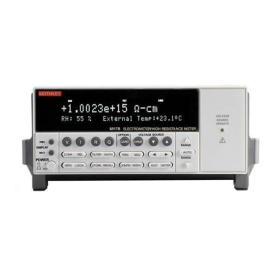
Section 2 Getting started In this section: Introduction ................2-1 Front panel summary ............... 2-1 Rear panel summary ..............2-3 Power-up .................. 2-5 Display ..................2-8 Navigating menus ..............2-17 Menu ..................2-18 Introduction This section contains identification and descriptions of controls and components of the Keithley Instruments Model 6517B Electrometer and detailed information for powering up the Model 6517B. - Page 25 Section 2: Getting started Model 6517B Electrometer Reference Manual ANNUNCIATORS EDIT: Editing voltage source values ERR: Questionable reading REM: In remote TALK: Addressed to talk LSTN: Addressed to listen SRQ: Service Request REL: Relative reading displayed ...
-
Page 26: Rear Panel Summary
Model 6517B Electrometer Reference Manual Section 2: Getting started VOLTAGE SOURCE OPERATE Indicator on when in operate, off when in standby. OPTION CARD KEY Use to program and operate an installed option. Also used to scan external scanner channels. - Page 27 Section 2: Getting started Model 6517B Electrometer Reference Manual COMMON Connector that is internally connected to INPUT low. CHASSIS GROUND Attached cable that connects the chassis to ground through the power line cord. COMMON can also be grounded by plugging the cable into COMMON. For floating measurements, make sure the cable connection between COMMON and Chassis Ground is open.
-
Page 28: Power-Up
Model 6517B Electrometer Reference Manual Section 2: Getting started Power-up Line power connection Follow the procedure below to connect the Model 6517B to line power and turn on the instrument. Operating the instrument on an incorrect line voltage may cause damage to the instrument, possibly voiding the warranty. -
Page 29: Power-Up Sequence
Section 2: Getting started Model 6517B Electrometer Reference Manual 1. On the side of the fuse holder are two small tabs. Use a small flat blade screwdriver to pry the fuse drawer open. 2. Slide the fuse drawer out to gain access to the fuses. Snap the old fuse out of the drawer and replace it with the same type. - Page 30 Model 6517B Electrometer Reference Manual Section 2: Getting started Power-up error messages The Model 6517B performs the following checksum tests on power-up. Data Type of storage IEEE-488 address Electrically-erasable PROM Power-up default Electrically-erasable PROM Calibration constants Electrically-erasable PROM Calibration dates Electrically-erasable PROM Instrument setups 10 in electrically-erasable PROM...
-
Page 31: Display
Section 2: Getting started Model 6517B Electrometer Reference Manual IEEE-488 primary address The IEEE-488 primary address of the instrument must be the same as the primary address you specify in the controller's programming language. The default primary address of the instrument is 27, but you can set the address to any value from 0 to 30 by using the MENU key. -
Page 32: Range Messages
Model 6517B Electrometer Reference Manual Section 2: Getting started Range messages The following display messages may occur when making measurements: OVERFLOW: This message is displayed when the integrated (average) input signal level (voltage, current, or charge) exceeds 105 % of full scale for the selected measurement range. For example, on the 20 nA measurement range, the OVERFLOW message occurs when the integrated input level exceeds 21 nA. - Page 33 Section 2: Getting started Model 6517B Electrometer Reference Manual Figure 3: Input signal Figure 4: Measurement on 20 nA range 2-10 6517B-901-01 Rev. C / August 2015...
-
Page 34: Status And Error Messages
Model 6517B Electrometer Reference Manual Section 2: Getting started Status and error messages During Model 6517B operation and programming, you encounter a number of front panel messages. Typical messages are either of status or error variety, as listed in the table below. The most recent status or error messages can be momentarily displayed by entering a configuration menu or the main menu, and pressing the PREV display key (the display is blank if no message is queued). - Page 35 Section 2: Getting started Model 6517B Electrometer Reference Manual Number Description Event -154 "String too long" -151 "Invalid string data" -150 "String data error" -148 "Character data not allowed" -144 "Character data too long" -141 "Invalid character data" -140 "Character data error" -128 "Numeric data not allowed"...
- Page 36 Model 6517B Electrometer Reference Manual Section 2: Getting started Number Description Event +306 "Reading Available"" +307 "Voltmeter Complete" +308 "Buffer Available" +309 "Buffer half-full" +310 "Buffer full +311 "Buffer Overflow" +312 "Buffer Pretriggered" +313 "Reading out of Limit" +315 "V-source compliance detected" +320 "Buffer &...
-
Page 37: Multiple Displays
Section 2: Getting started Model 6517B Electrometer Reference Manual Number Description Event +860 "Interlock Violation Error" +861 "Vsource Limit too low for auto" +900 "Internal System Error" +950 "DDC Reading overflow" +951 "DDC Reading Available" +952 "DDC Buffer full" +953 "DDC Mode IDDC Error"... - Page 38 Model 6517B Electrometer Reference Manual Section 2: Getting started Time/day/date This display provides the time, day of week, and the date. The time, date and format (12-hour or 24- hour) are set from the CLOCK option of the GENERAL MENU (which is selected from the MAIN MENU).
- Page 39 Section 2: Getting started Model 6517B Electrometer Reference Manual Zero-centered bar graph The zero-centered bar graph is a graphical representation of a reading with positive and negative limits (see figure below). The limits are expressed in a user-selectable percentage of range. The vertical lines displayed along the bar designate the positive and negative limits, zero, and halfway to either limit.
-
Page 40: Navigating Menus
Model 6517B Electrometer Reference Manual Section 2: Getting started Navigating menus Menu types There are two types of menu structures; the Main Menu and the Configure menus. The Main Menu accesses items for which there are no dedicated keys, and Configure menus are used to configure measurement functions and other instrument operations. -
Page 41: Menu
Section 2: Getting started Model 6517B Electrometer Reference Manual Menu The main menu accesses the various instrument operations for which there are no dedicated keys, such as setup storage, communication setup, calibration, self-test and limits. The main menu structure is summarized in the following table, along with the reference section number that includes more detailed information on that particular menu selection. -
Page 42: Savesetup
Model 6517B Electrometer Reference Manual Section 2: Getting started Menu item Description Section LIMITS Limits menu: LIMIT-SET-1 Limit-Set-1 menu: CONTROL Enable/disable limit set #1 LOLIM1 Set value of low limit #1 HILIM1 Set value of high limit #1 LIMIT-SET-2 Limit-Set-2 menu: CONTROL Enable/disable limit set #2 LOLIM2... - Page 43 Section 2: Getting started Model 6517B Electrometer Reference Manual SAVE Use this menu item to save the present instrument setup in a specific memory location. You can store up to 10 setups in non-volatile memory. After selecting SAVE, you are prompted to save the present setup in a memory location. Note that the numbering of setup locations starts with setup #0.
- Page 44 Model 6517B Electrometer Reference Manual Section 2: Getting started RESET Use this menu option to reset the instrument to the bench or GPIB default conditions shown in the table below. The RESET options are: BENCH: The instrument returns to the bench default conditions. After selecting BENCH, the instrument returns to the normal display of readings after requesting an ENTER to confirm your selection.
- Page 45 Section 2: Getting started Model 6517B Electrometer Reference Manual Digital Output: States No effect No effect Logic Sense No effect No effect Display Numeric Format Engineering Engineering Scientific Format Floating Exp Floating Exp Decimal Character Period Period Temperature Units °C °C Filter Digital filter...
- Page 46 Model 6517B Electrometer Reference Manual Section 2: Getting started R (Ohms): Amps Rel Damping Measurement Type Resistance Resistance Resistivity Type Surface Surface Fixture User User Ks, Kv Thickness 1.0 mm 1.0 mm R (Ohms): Auto V-source Ohms Range 2 M 2 M...
- Page 47 Section 2: Getting started Model 6517B Electrometer Reference Manual Test sequence Diode Diode Diode: Start Voltage Stop Voltage 10 V 10 V Step Voltage Delay Capacitor: Bias Voltage Points Interval Cable: Bias Voltage Points Interval Resistor: Source V1 Delay 1 Source V2 Delay 2 Surface Resistivity:...
- Page 48 Model 6517B Electrometer Reference Manual Section 2: Getting started Test sequence SIR: Bias Voltage 50 V 50 V Bias Time Measure Voltage 100 V 100 V Measure Time Square Wave Sweep: High Level High Time Low Level -1 V -1 V Low Time Cycle Count Staircase Sweep:...
-
Page 49: Test
Section 2: Getting started Model 6517B Electrometer Reference Manual V-source: Range 100 V 100 V Voltage Limit Value 1000 V 1000 V Resistive I-Limit Meter Connect Zero Check Note: The default selects all elements except HUM, DT, and ET. COMMUNICATION The COMMUNICATION menu option allows you to select and configure the GPIB or RS-232 bus. -
Page 50: General
Model 6517B Electrometer Reference Manual Section 2: Getting started GENERAL The GENERAL menu is used for the following operations: To control the state and sense of the digital outputs. To view the serial number, SCPI version, and firmware revision levels of the Model 6517B. ... - Page 51 Section 2: Getting started Model 6517B Electrometer Reference Manual A/D CONTROLS With this GENERAL menu item, you can control line synchronization, and enable or disable humidity and external temperature measurements. LINE-SYNC: Synchronizing A/D conversions with the power line frequency increases common mode and normal mode rejection.
- Page 52 Model 6517B Electrometer Reference Manual Section 2: Getting started TIMESTAMP A time stamp is available for readings sent over the bus and for readings stored in the buffer. This GENERAL menu selection is used to configure the time stamp for readings sent over the bus. From the front panel, readings are sent over the bus through the COMMUNICATION selection of the MAIN menu.
- Page 53 Section 2: Getting started Model 6517B Electrometer Reference Manual DISPLAY This menu item is used to select the exponent mode (engineering units or scientific notation) for display readings, and lets you specify displayed decimal points as either periods or commas: NUMERIC-FORMAT: This item is used to select the exponent mode: ...
-
Page 54: Connections
Section 3 Connections In this section: Introduction ................3-1 Electrometer input connector ........... 3-1 Connection methods ..............3-4 Low-noise cables, shielding, and guarding ......3-6 Floating circuits ................ 3-9 Test fixtures ................3-11 Introduction This section contains basic information on electrometer, high-resistance meter, and V-source connections. -
Page 55: Input Configurations
Section 3: Connections Model 6517B Electrometer Reference Manual Input configurations The input connector can be configured with guard off or guard on. With GUARD off, input low is connected to the inner shell of the connector, as shown in the following figure. -
Page 56: Input Protection
Model 6517B Electrometer Reference Manual Section 3: Connections Connecting PREAMP OUTPUT, COMMON, or 2V ANALOG OUTPUT to earth while floating the input may damage the instrument. Figure 11: Maximum input levels Input protection The Model 6517B incorporates protection circuitry against nominal overload conditions. However, a high voltage (>250 V) and resultant current surge could damage the input circuitry. -
Page 57: Connection Methods
Section 3: Connections Model 6517B Electrometer Reference Manual Adding a resistor and two diodes (1N3595), as shown in the following figure, provides considerable extra protection. The resistor must be large enough to limit the current through the diodes to 10 mA or less. -
Page 58: Voltage Source Output Connections
Model 6517B Electrometer Reference Manual Section 3: Connections V-SOURCE LO connected to ammeter input LO through the METER-CONNECT option of CONFIGURE V-SOURCE Menu. The equivalent circuit for this configuration is shown in the following figure. Figure 15: Force voltage measure current - equivalent circuit Voltage source output connections The voltage source output is accessed at the rear panel V SOURCE OUT HI and LO binding posts as shown in the following figure. -
Page 59: V-Source Probes And Cables
Section 3: Connections Model 6517B Electrometer Reference Manual The V-source can also be used be with the Electrometer to form the FVMI configuration as described High-resistance meter connections (on page 3-4). This configuration is used for resistance measurements and current measurements. For these measurements, V-source LO and ammeter input LO can be connected internally through the METER-CONNECT option of the CONFIGURE V- SOURCE menu. -
Page 60: Low-Noise Input Cables
Model 6517B Electrometer Reference Manual Section 3: Connections Low-noise input cables Triaxial cables can generate enough triboelectric currents to corrupt the measurement. These currents are caused by friction between the center conductor and the inner shield when the cable is flexed or allowed to move around. - Page 61 Section 3: Connections Model 6517B Electrometer Reference Manual Use noise shield for: Unguarded voltage measurements Unguarded current measurements (below 1 µA) Low-level charge measurements Typically, the noise shield is connected to electrometer input LO. However, sometimes better noise performance can be achieved by instead connecting the noise shield to both electrometer LO and chassis ground.
-
Page 62: Floating Circuits
Model 6517B Electrometer Reference Manual Section 3: Connections Use guard for: Guarded voltage measurement Guarded, floating current measurements For voltage measurements, guarding should be used when the test circuit impedance is 1 G or when long input cables are used. Guard is enabled from the Configure Voltage menu structure. When enabled, the guard potential is placed on the inner shield of the triaxial input cable. -
Page 63: Floating Measurements
Section 3: Connections Model 6517B Electrometer Reference Manual Floating measurements The figures below show two examples where the Model 6517B floats at a hazardous voltage level. In the following figure, a shock hazard (100 V) exists between meter input LO and chassis ground. If meter input LO is connected to a noise shield, the shock hazard is also present on that shield. -
Page 64: Test Fixtures
Model 6517B Electrometer Reference Manual Section 3: Connections Connecting PREAMP OUTPUT, COMMON, or 2V ANALOG OUTPUT to earth (chassis) ground while floating the input may damage the instrument. Figure 23: Floating V-source Test fixtures Whenever possible, use shielded, low leakage test fixtures to make precision measurements. Keithley Instruments Model 8009 test fixture This test fixture allows volume resistivity in the range from 103 to 1018 -cm, and surface resistivity in the range from 103 to 1017 /sq. -
Page 65: Custom Built Test Fixtures
Section 3: Connections Model 6517B Electrometer Reference Manual Custom built test fixtures Two examples of custom built test fixtures are shown in the following figures. The first is a dedicated test fixture to source voltage and measure current to a single DUT (resistance measurements). The second is a multi-purpose test fixture that can be used to make any Model 6517B measurement. - Page 66 Model 6517B Electrometer Reference Manual Section 3: Connections Connectors, terminals, and internal wiring The following figures show the types of connectors needed to use the test fixtures with the Model 6517B. All connectors, except the triaxial connector, must be insulated from the chassis of the test fixture.
- Page 67 Section 3: Connections Model 6517B Electrometer Reference Manual Figure 25: Multipurpose test fixture Interlock When a normally-open, SPST momentary switch is properly implemented as a safety interlock, the V- source goes into standby whenever the test fixture lid is open or ajar. The switch must be mounted inside the test box such that it is closed when the lid of the test fixture is closed.
- Page 68 Model 6517B Electrometer Reference Manual Section 3: Connections Handling and cleaning test fixtures Dust, body oil, solder flux, and other contaminants on connector and terminal insulators can significantly decrease the leakage resistance resulting in excessive leakage currents. Also, contaminants on DUT and test circuit components can create a leakage path. These leakage currents may be large enough to corrupt low-level measurements.
-
Page 69: Basic Measurements
Section 4 Basic measurements In this section: Introduction ................4-1 Voltage measurements ............4-1 Current measurements ............4-9 Resistance and resistivity measurements ......4-18 Charge measurements (Q)............. 4-31 Other measurement considerations ........4-35 Introduction This section discusses front panel triggering, trigger configuration, and external triggering, including example setups. -
Page 70: Basic Measurement Procedure
Section 4: Basic measurements Model 6517B Electrometer Reference Manual Basic measurement procedure The voltage measurement procedure is summarized below. To ensure proper operation, always enable zero check (“ZeroCheck” displayed) before changing functions (V, I, R, or Q). The Z-CHK key controls zero check. - Page 71 Model 6517B Electrometer Reference Manual Section 4: Basic measurements Figure 29: Guard voltage measurements - connections Figure 30: Guarded voltage measurements - equivalent circuit 6517B-901-01 Rev. C / August 2015...
-
Page 72: Volts Configuration
Section 4: Basic measurements Model 6517B Electrometer Reference Manual Volts configuration The following information explains the various configuration options for the volts function. The configuration menu is summarized in the table below. This menu is accessed by pressing CONFIG and then V. Note that a function does not have to be selected in order to be configured. When the function is selected, it assumes the programmed status. - Page 73 Model 6517B Electrometer Reference Manual Section 4: Basic measurements EXT- FDBK This option is used to enable or disable the external feedback mode. The following menu items are used to control external feedback: OFF: Disable external feedback ON: Enable external feedback SPEED The speed parameter sets the integration time of the analog to digital (A/D) converter, the period of time the input signal is measured (also known as aperture).
-
Page 74: Voltage Measurement Considerations
Section 4: Basic measurements Model 6517B Electrometer Reference Manual Voltage measurement considerations Some considerations for making accurate voltage measurements are summarized in the following paragraphs. For comprehensive information on precision measurements, refer to the Low Level Measurements Handbook, which is available from Keithley Instruments. Loading effects Circuit loading can be detrimental to high-impedance voltage measurements. - Page 75 Model 6517B Electrometer Reference Manual Section 4: Basic measurements Input capacitance At very high resistance levels, the very large time constants created by even a minimal amount of capacitance can slow down response time considerably. For example, measuring a source with an internal resistance of 100 G...
- Page 76 Section 4: Basic measurements Model 6517B Electrometer Reference Manual Figure 32: Unguarded voltage measurements 6517B-901-01 Rev. C / August 2015...
-
Page 77: Current Measurements
Model 6517B Electrometer Reference Manual Section 4: Basic measurements Guarding the circuit minimizes these effects by driving the inner shield of the triaxial cable at signal potential, as shown in the following figure. Here, a unity gain amplifier with a high input impedance and low output impedance is used. -
Page 78: Basic Measurement Procedure
Section 4: Basic measurements Model 6517B Electrometer Reference Manual Basic measurement procedure To achieve optimum precision for low-level current measurements, input bias current and voltage burden can be minimized by performing the offset adjustment procedure. After measuring high voltage in the volts function, it may take a number of minutes for input current to drop to within specified limits. - Page 79 Model 6517B Electrometer Reference Manual Section 4: Basic measurements Figure 36: Guarded floating current measurement connections Use for floating circuit where leakage from ammeter input to circuit low is a consideration. 6517B-901-01 Rev. C / August 2015 4-11...
-
Page 80: Amps Configuration
Section 4: Basic measurements Model 6517B Electrometer Reference Manual Amps configuration The following information explains the various configuration options for the amps function. The configuration menu is summarized in the following table. This menu is accessed by pressing CONFIG and then I. Note that a function does not have to be selected in order to be configured. -
Page 81: Current Measurement Considerations
Model 6517B Electrometer Reference Manual Section 4: Basic measurements RESOLUTION The RESOLUTION parameter sets the display resolution. AUTO-RANGE The AUTO-RANGE option is used to configure autorange for the amps function. This option allows you to speed up the autoranging search process by eliminating upper and lower measurement ranges. - Page 82 Section 4: Basic measurements Model 6517B Electrometer Reference Manual Voltage burden The input resistance of the ammeter causes a small voltage drop across the input terminals. This voltage is known as the voltage burden. If the voltage burden is large in relation to the voltage of the measured circuit, then significant measurement errors occur.
- Page 83 Model 6517B Electrometer Reference Manual Section 4: Basic measurements Note that as R decreases in value, the output noise increases. For example, when R , the input noise is multiplied by a factor of two. Since decreasing the source resistance can have a detrimental effect on noise performance, there are usually minimum recommended source resistance values based on measurement range.
- Page 84 Section 4: Basic measurements Model 6517B Electrometer Reference Manual Note that as C increases in value, Z decreases in value, thereby increasing the noise gain. Again, at the point where Z , the input noise is amplified by a factor of two. The maximum value of source capacitance (C ) for the Model 6517B ammeter is 10,000 pF.
- Page 85 Model 6517B Electrometer Reference Manual Section 4: Basic measurements Floating current measurements As discussed previously, guarding uses a conductor at essentially the same potential as the sensitive input to drastically reduce leakage currents in high impedance test circuits. No current can flow when there is a 0 V drop across a leakage resistance.
-
Page 86: Resistance And Resistivity Measurements
Section 4: Basic measurements Model 6517B Electrometer Reference Manual Resistance and resistivity measurements The Model 6517B can make resistance measurements and resistivity measurements (surface and volume). High resistance measurements (above 1 MΩ) may exhibit problematic background currents and can be improved using the alternating polarity test sequence. Auto V-source The Model 6517B has an auto V-source mode for resistance and resistivity measurements. -
Page 87: Ohms Ranges
Model 6517B Electrometer Reference Manual Section 4: Basic measurements Ohms ranges Each measurement range for the ohms function has a lower reading limit that is one decade below the selected range. For example, the 20 MΩ range has a lower reading limit of 2 MΩ. The reading ranges for the ohms function are listed in the following table. -
Page 88: Resistance Measurements
Section 4: Basic measurements Model 6517B Electrometer Reference Manual Resistance measurements The Model 6517B can make resistance measurements up to 1017 Ω using the force voltage measure current (FVMI) technique. From the known sourced voltage and measured current, the Model 6517B calculates and displays the resultant resistance (R = V/I). - Page 89 Model 6517B Electrometer Reference Manual Section 4: Basic measurements 5. Select the ohms function by pressing the R key. 6. If the manual V-source adjustment mode is selected, use the cursor keys and the VOLTAGE SOURCE adjustment keys to set the voltage level. The V-source range can be changed from the RANGE item of the CONFIGURE V-SOURCE menu.
-
Page 90: Resistivity Measurements
Section 4: Basic measurements Model 6517B Electrometer Reference Manual Cancelling test fixture leakage current Significant leakage in the test fixture can corrupt a resistance measurement. This leakage current can be cancelled by performing a REL on the current component of the resistance measurement. The following procedure assumes that steps 1 through 7 of the preceding resistance measurement procedure have been performed. - Page 91 Model 6517B Electrometer Reference Manual Section 4: Basic measurements Surface resistivity Surface resistivity is defined as the electrical resistance of the surface of an insulator material. It is measured from electrode to electrode along the surface of the insulator sample. Since the surface length is fixed, the measurement is independent of the physical dimensions (for example, thickness and diameter) of the insulator sample.
- Page 92 Section 4: Basic measurements Model 6517B Electrometer Reference Manual For circular electrodes: P = D + g (refer to the "Circular electrode dimensions" figure to determine dimension D Figure 46: Circular electrode dimensions Volume resistivity Volume resistivity is defined as the electrical resistance through a cube of insulating material. When expressed in ohm-centimeters, it would be the electrical resistance through a one-centimeter cube of insulating material.
- Page 93 Model 6517B Electrometer Reference Manual Section 4: Basic measurements Where: = Volume resistivity. = The effective area of the guarded electrode for the particular electrode arrangement employed. = Average thickness of the sample (mm). R = Measured resistance in ohms (V/I).
- Page 94 Section 4: Basic measurements Model 6517B Electrometer Reference Manual 1. Enable zero check by pressing Z-CHK. 2. Select and configure the desired resistivity measurement type from the MEAS-TYPE (RESISTIVITY) option of the ohms configuration menu (refer to Ohms configuration (on page 4- 27) for more information).
-
Page 95: Ohms Configuration
Model 6517B Electrometer Reference Manual Section 4: Basic measurements Ohms configuration The following information explains the various configuration options for the ohms function. The configuration menu is summarized in the table below. This menu is accessed by pressing CONFIG and then R. Note that a function does not have to be selected in order to be configured. - Page 96 Section 4: Basic measurements Model 6517B Electrometer Reference Manual FILTER Use this menu item to configure the two basic filter types; averaging and median. Note that you can use either the averaging filter, the median filter, or both. The filter menu is available from the function configuration menus (for example, press CONFIG V) or by pressing CONFIG FILTER with the desired function already selected.
- Page 97 Model 6517B Electrometer Reference Manual Section 4: Basic measurements MEAS-TYPE The MEAS-TYPE option is used to select and configure the measurement type for the ohms function. RESISTANCE: Use this menu item to configure the ohms function to make normal resistance measurements.
-
Page 98: Ohms Measurement Considerations
Section 4: Basic measurements Model 6517B Electrometer Reference Manual Multiple display There is one multiple display that is unique to the ohms function. Measure/source: When this NEXT display is selected, the amps measurement and V-source value are shown on the secondary display. The resistance measurement is shown on the primary display. Ohms measurement considerations Some considerations for making accurate resistance and resistivity measurements are summarized in the following paragraphs. -
Page 99: Charge Measurements (Q)
Model 6517B Electrometer Reference Manual Section 4: Basic measurements Current measurement considerations Ohms measurements are performed by forcing voltage and measuring current (FVMI). Thus, accurate measurements require accurate current measurements. Capacitive inputs increase preamplifier noise, resulting in increased noise across the voltage source terminals (refer to Other measurement considerations (on page 4-35) for additional measurement considerations). - Page 100 Section 4: Basic measurements Model 6517B Electrometer Reference Manual Procedure Use the following basic procedure to make charge measurements. To ensure proper operation, always enable zero check ("ZeroCheck" displayed) before changing functions (V, I, R, or Q). The Z- CHK key controls zero check. 1.
-
Page 101: Coulombs Configuration
Model 6517B Electrometer Reference Manual Section 4: Basic measurements Coulombs configuration The following information explains the various configuration options for the coulombs function. The configuration menu is summarized in the following table. This menu is accessed by pressing CONFIG and then Q. Note that you do not have to select a function to configure it. -
Page 102: Charge Measurement Considerations
Section 4: Basic measurements Model 6517B Electrometer Reference Manual AUTO-DISCHARGE The AUTO-DISCHARGE option is used to enable or disable auto discharge. When enabled, auto discharge resets the charge reading to zero at the specified level. After the integrator resets, the charge measurement process simply restarts at zero. -
Page 103: Other Measurement Considerations
Long measurement times may degrade charge measurement accuracy. See the Model 6517B coulombs Specifications, available on the Keithley Instruments support website (http://www.tektronix.com/keithley). Zero check hop and auto discharge hop Using the zero check feature (going from the enabled state to the disabled state) causes a sudden change in the charge reading and is known as zero check hop. -
Page 104: Triboelectric Effects
Section 4: Basic measurements Model 6517B Electrometer Reference Manual To prevent ground loops, instruments should be connected to ground at only a single point, as shown in the following figure. Note that only a single instrument is connected directly to power line ground. Experimentation is the best way to determine an acceptable arrangement. -
Page 105: Electrochemical Effects
Model 6517B Electrometer Reference Manual Section 4: Basic measurements Electrochemical effects Error currents also arise from electrochemical effects when ionic chemicals create weak batteries on a circuit board. These batteries could generate a few nanoamps of current between conductors. Ionic contamination may be the result of body oils, salts or solder flux. -
Page 106: Magnetic Fields
Section 4: Basic measurements Model 6517B Electrometer Reference Manual Electrostatic interference is first recognizable when hand or body movements near the experiment cause fluctuations in the reading. Pick-up from AC fields can also be detected by observing the electrometer preamp output on an oscilloscope. Line frequency signals on the output are an indication that electrostatic interference is present. -
Page 107: Relative Humidity And External Temperature Readings
Model 6517B Electrometer Reference Manual Section 4: Basic measurements The effect on instrument performance can be considerable if enough of the unwanted signal is present. The effects of EMI can be seen as an unusually large offset, or in the case of impulse sources, erratic variations in the displayed reading. -
Page 108: Measurement Options
Section 5 Measurement options In this section: Introduction ................5-1 Voltage source ................. 5-1 Analog outputs ................. 5-7 Using external feedback ............5-10 Range and resolution ............. 5-17 Zero check, relative, and zero correct ........5-19 Introduction This section contains detailed information on measurement options, such as using the voltage source, analog output, and preamp output. -
Page 109: V-Source Configuration
Section 5: Measurement options Model 6517B Electrometer Reference Manual Capacitive inputs increase preamplifier noise, resulting in noise across the voltage source terminals. V-Source configuration Operations to configure the V-source are performed from the V-source configuration menu which is summarized in the following table. The CONFigure V-SOURCE menu is displayed by pressing CONFIG and then OPER. - Page 110 Model 6517B Electrometer Reference Manual Section 5: Measurement options Independent source When used as an independent source, voltage is available at the V-SOURCE HI and LO terminals on the rear panel (see the figure below). In this configuration, the V-source functions as a stand-alone voltage source.
-
Page 111: Setting Voltage Source Value
Section 5: Measurement options Model 6517B Electrometer Reference Manual Figure 56: V-source (FVMI configuration) - equivalent circuit Ammeter LO internally connected to V-source LO through METER Connect option of CONFIG V- source menu. When the voltage source is connected to a capacitor, the inherent noise of the preamplifier is amplified. -
Page 112: Voltage And Current Limit
Model 6517B Electrometer Reference Manual Section 5: Measurement options Selecting voltage source range The voltage source range cannot be changed while in Auto V-source Ohms. With the voltage source value displayed, the position of the decimal point denotes the currently selected range. For example, a reading of 000.000 V is 0 V on the 100 V range, while a reading of 0000.00 V is 0 V on the 1000 V range. -
Page 113: Interlock And Test Fixtures
Section 5: Measurement options Model 6517B Electrometer Reference Manual Setting a voltage limit While in Auto V-source Ohms, the voltage limit of the V-source can only be set to a value that is >400 V. The V-source can be set to a maximum absolute value of voltage that can be sourced. For example, setting a value of 30 V limits the voltage output from -30 V to +30 V. -
Page 114: Operate
Model 6517B Electrometer Reference Manual Section 5: Measurement options Operate Hazardous voltages may be present on the output and guard terminals. To prevent electrical shock that could cause injury or death, NEVER make or break connections to the Model 6517B while the output is on. Power off the equipment from the front panel or disconnect the main power cord from the rear of the Model 6517B before handling cables connected to the outputs. -
Page 115: Analog Output
Section 5: Measurement options Model 6517B Electrometer Reference Manual 2 V analog output The 2 V ANALOG OUTPUT provides a scaled 0 to 2 V output that is non-inverting in the volts mode. Connections for using this output are shown in the following figure. For a full-range input, the output is 2 V;... -
Page 116: Preamp Out
Model 6517B Electrometer Reference Manual Section 5: Measurement options Preamp out The PREAMP OUT of the Model 6517B follows the signal amplitude applied to the INPUT terminal. Some possible uses for the inverting PREAMP OUT include buffering of the input signal, as well as for guarding in the volts mode. -
Page 117: Using External Feedback
Section 5: Measurement options Model 6517B Electrometer Reference Manual Figure 59: Typical PREAMP OUT connections Figure 60: Typical PREAMP OUT connections - equivalent circuits Using external feedback The external feedback function provides a means to extend the capabilities of the Model 6517B Electrometer to such uses as logarithmic currents, non-decade current ranges, as well as non- standard coulombs ranges. -
Page 118: Electrometer Input Circuitry
Model 6517B Electrometer Reference Manual Section 5: Measurement options Electrometer input circuitry A simplified diagram of the electrometer input in the external feedback mode is shown in the following figure. An input current applied to the inverting (-) input of the operational amplifier (op amp) is nulled by a current feedback through the internal feedback network made up of R and C . - Page 119 Section 5: Measurement options Model 6517B Electrometer Reference Manual When using external feedback, the following factors must be taken into account: The maximum current value that can be supplied by the preamp output is 20 mA in amps and ohms (1 mA in volts).
-
Page 120: Shielded Fixture Construction
Model 6517B Electrometer Reference Manual Section 5: Measurement options Shielded fixture construction Since shielding is so critical for proper operation of external feedback, it is recommended that a shielded fixture similar to the one shown in the figure below be used to house the feedback element. The fixture is constructed of a commercially available shielded fixture modified with the standard BNC connectors replaced with triaxial female connectors. -
Page 121: External Feedback Procedure
Section 5: Measurement options Model 6517B Electrometer Reference Manual External feedback procedure Use the following procedure to operate the Model 6517B in the external feedback mode. 1. Connect the feedback element between the PREAMP OUT terminal and the Input High terminal. 2. -
Page 122: Logarithmic Currents
Model 6517B Electrometer Reference Manual Section 5: Measurement options Logarithmic currents The use of a diode junction in the external feedback path permits a logarithmic current-to-voltage conversion. This relationship for a junction diode is given by the equation: V = mkT / q ln(I/I ) + I Where: ... - Page 123 Section 5: Measurement options Model 6517B Electrometer Reference Manual Using the above transistors, a minimum RC time constant of 100 µs at maximum input current would be used. At I (max) of 100 µA, this value would correspond to 0.4 µF. Note that at 100 nA, this value would increase the RC response time constant to 100 ms.
-
Page 124: Non-Decade Current Gains
Model 6517B Electrometer Reference Manual Section 5: Measurement options Non-decade current gains The Model 6517B electrometer input uses internal decade resistance feedback networks for the current ranges. In some applications, non-decade current gains may be desirable. As shown in the figure below, an external feedback resistor, R , can be used to serve this purpose. -
Page 125: Display Resolution
Section 5: Measurement options Model 6517B Electrometer Reference Manual Display resolution The Model 6517B can display readings at 3.5, 4.5, 5.5, or 6.5 digit resolution. The display resolution of a reading depends on the selected resolution setting (fixed or auto). The default display resolution for every function is 5.5 digits. -
Page 126: Zero Check, Relative, And Zero Correct
Model 6517B Electrometer Reference Manual Section 5: Measurement options Zero check, relative, and zero correct Zero check When zero check is enabled (on), the input amplifier is reconfigured to shunt the input signal to low as shown in the figure below. When you enable or disable zero check, that state is assumed regardless of which function you select. -
Page 127: Relative (Rel)
Section 5: Measurement options Model 6517B Electrometer Reference Manual Relative (REL) The REL (relative) operation subtracts a reference value from actual readings. When REL is enabled by the REL key, the instrument uses the present reading as a relative value. Subsequent readings are the difference between the actual input value and the REL value. -
Page 128: Zero Correct
Model 6517B Electrometer Reference Manual Section 5: Measurement options Multiple display of REL One of the "multiple displays" allows you to view the reading without REL applied on the bottom line of the display and the REL’d reading on the top line. The display is available by repeatedly pressing either the PREV or NEXT DISPLAY key to scroll through the multiple displays of the particular function. -
Page 129: Test Sequences
Section 6 Test sequences In this section: Introduction ................6-1 Test sequences ................ 6-1 Test descriptions ..............6-1 Configuring test sequences ............ 6-12 Introduction This section contains detailed information on built-in test sequences available with the Keithley Instruments Model 6517B Electrometer. Test sequences The Model 6517B has the following built-in test sequences: ... -
Page 130: Diode Leakage Current Test
Section 6: Test sequences Model 6517B Electrometer Reference Manual Diode leakage current test This test is used to measure the leakage current for a diode. The following figure shows the connections and the simplified schematic. By sourcing a positive voltage, the leakage current through the diode is measured. - Page 131 Model 6517B Electrometer Reference Manual Section 6: Test sequences Figure 68: Diode leakage current test default measurement points 6517B-901-01 Rev. C / August 2015...
-
Page 132: Capacitor Leakage Current Test
Section 6: Test sequences Model 6517B Electrometer Reference Manual Capacitor leakage current test This test is used to measure the leakage current for a capacitor. The magnitude of the leakage is dependent on the type of dielectric and the applied voltage. The following figure shows the connections for this test. -
Page 133: Cable Insulation Resistance Test
Model 6517B Electrometer Reference Manual Section 6: Test sequences Cable insulation resistance test This test is used to measure the insulation resistance of a cable. The below figure shows the connections for this test. The resistance of the insulator between the shield and the inner conductor is being measured. -
Page 134: Standard Method Resistivity Tests
Section 6: Test sequences Model 6517B Electrometer Reference Manual This test makes two resistance measurements at two different voltage levels, and calculates the voltage coefficient. The test circuit is shown in the following figure. The resistor should be placed in a shielded test fixture that is designed to minimize leakage resistance. -
Page 135: Alternating Polarity Resistance/Resistivity Test
Model 6517B Electrometer Reference Manual Section 6: Test sequences Alternating polarity resistance/resistivity test The alternating polarity resistance/resistivity test is designed to improve high resistance/resistivity measurements. These measurements are prone to large errors due to background currents. By using an alternating stimulus voltage, it is possible to eliminate the effects of these background currents. This test measures surface or volume resistivity or resistance, as selected in the CONFIGURE RESISTANCE menu. - Page 136 Section 6: Test sequences Model 6517B Electrometer Reference Manual 6517B-901-01 Rev. C / August 2015...
-
Page 137: Surface Insulation Resistance (Sir) Test
Model 6517B Electrometer Reference Manual Section 6: Test sequences Surface insulation resistance (SIR) test This test is used to measure the insulation resistance between PC-board traces. The following figure shows the connections and the equivalent circuit. Note that the drawing shows a "Y" test pattern for the measurement. -
Page 138: Sweep Tests (Square Wave And Staircase)
Section 6: Test sequences Model 6517B Electrometer Reference Manual Sweep tests (square wave and staircase) The sweep tests are not geared to any specific application. These voltage/measure sweeps can be used for any type of measurement; volts, amps, ohms or coulombs. Thus, make sure to select the measurement function before running one of these tests. - Page 139 Model 6517B Electrometer Reference Manual Section 6: Test sequences Figure 76: Staircase sweep test default measurement points 6517B-901-01 Rev. C / August 2015 6-11...
-
Page 140: Configuring Test Sequences
Section 6: Test sequences Model 6517B Electrometer Reference Manual Configuring test sequences Configure sequence menu The CONFIGURE SEQUENCE menu is used to select and configure a test sequences and is summarized in the below table. The top level of the menu is displayed by pressing CONFIG and then SEQ. - Page 141 Model 6517B Electrometer Reference Manual Section 6: Test sequences ALT-POLARITY Alternate polarity test: V-OFS Specify offset voltage V-ALT Specify alternating voltage 10 V MEAS-TIME Specify measurement time 15 s DISCARD RDGS Specify discarded readings STORE RDGS Specify readings to store SUR-INSUL-RES-TEST Surface insulation resistance test: BIAS V...
-
Page 142: Menu Sections
Section 6: Test sequences Model 6517B Electrometer Reference Manual Menu sections APPLICATIONS This menu item is used to select the application: DEV-CHAR: Use this menu item to select and configure one of the device characterization tests: DIODE: Use this option to select and configure the diode leakage current test. After selecting LEAKAGE-CURRENT, you are prompted to enter the start voltage, stop voltage, step voltage and the delay. - Page 143 Model 6517B Electrometer Reference Manual Section 6: Test sequences STAIRCASE: Use this option to select and configure the staircase sweep test. You are prompted to enter the start voltage, stop voltage, step voltage, and the step time. After entering these test parameters, use the EXIT key to back out of the menu structure. Running the selected test Perform the following steps to run the selected test: 1.
-
Page 144: Triggering
Section 7 Triggering In this section: Introduction ................7-1 Trigger configuration menu ............7-2 Trigger models ................. 7-3 Trigger configuration ..............7-9 External triggering ..............7-16 Introduction This section discusses front-panel triggering, trigger configuration, and external triggering, including example setups. -
Page 145: Trigger Configuration Menu
Section 7: Triggering Model 6517B Electrometer Reference Manual Trigger configuration menu The Keithley Instruments Model 6517B Electrometer triggers are set up from the CONFIGURE TRIGGER menu. The menu structure is shown and summarized in the following table. Notice that there are two trigger configuration structures: BASIC and ADVANCED. The basic menu structure can be used when simple trigger operations suffice. -
Page 146: Trigger Models
Model 6517B Electrometer Reference Manual Section 7: Triggering SCAN Scan layer menu: SOURCE Select scan source: IMMEDIATE Use to pass operation immediately into the measure layer EXTERNAL Use external triggers to control scanning MANUAL Use TRIG key to control scanning GPIB Use bus triggers to control scanning TRIGLINK... -
Page 147: Basic Trigger Model
Section 7: Triggering Model 6517B Electrometer Reference Manual Basic trigger model The below graphic illustrates the basic trigger model. It provides the fundamental trigger options needed for many instrument operations. Figure 77: Basic trigger model Basic triggering is selected and configured from the BASIC menu item of the CONFIGURE TRIGGER menu. - Page 148 Model 6517B Electrometer Reference Manual Section 7: Triggering Control sources With the one-shot trigger mode selected, a measurement (device action) does not occur until the selected control source event is detected. The control sources are explained as follows: Immediate: With this control source selected, event detection is immediately satisfied allowing operation to continue.
-
Page 149: Advanced Trigger Model
Section 7: Triggering Model 6517B Electrometer Reference Manual Advanced trigger model The following figure is the advanced trigger model, which provides more triggering options, programmed from the ADVANCED menu item of the CONFIGURE TRIGGER menu. Note that scanning operations use this trigger model. Figure 78: Advanced trigger model Advanced triggering is selected and configured from the ADVANCED menu item of the CONFIGURE TRIGGER menu. -
Page 150: Trigger Model Layers
Model 6517B Electrometer Reference Manual Section 7: Triggering Idle The instrument is considered to be in the idle state whenever it is not operating within one of the three layers of the trigger model. The front panel ARM indicator is off when the instrument is in the idle state. - Page 151 Section 7: Triggering Model 6517B Electrometer Reference Manual Source bypasses As seen in the previous figure, each layer has a path that allows operation to loop around the control source. Each path is called a source bypass. When a source bypass is enabled, and the external or trigger link (triglink) control source is selected, operation loops around the control source on the initial pass through the layer.
-
Page 152: Trigger Configuration
Model 6517B Electrometer Reference Manual Section 7: Triggering Trigger configuration Basic trigger configuration The following information explains how to configure the Model 6517B for basic triggering. If you instead wish to use advance triggering, see Advanced trigger configuration (on page 7-9). Basic triggering is configured from the BASIC item of the CONFIGURE TRIGGER menu, which is displayed by pressing the CONFIG key and then the TRIG key. - Page 153 Section 7: Triggering Model 6517B Electrometer Reference Manual Configuring measure layer The measure layer is used for the following operations: To select the measuring event (SOURCE) for the instrument To delay operation in the measure layer To designate the number of measurements the instrument makes (COUNT) ...
- Page 154 Model 6517B Electrometer Reference Manual Section 7: Triggering SOURCE This menu item selects the event that controls the measure source. IMMEDIATE: With this selection, events (such as TIMER and EXTERNAL triggers) do not control the measurement interval. Once the Model 6517B starts measuring, it takes readings as fast as its measurement configuration allows.
- Page 155 Section 7: Triggering Model 6517B Electrometer Reference Manual HOLD: When HOLD is selected, the measure source is suppressed. As a result, measuring is stopped and does not continue until HOLD is canceled by selecting one of the other measure source selections.
- Page 156 Model 6517B Electrometer Reference Manual Section 7: Triggering Configuring scan layer The scan layer is used for the following operations: To select the scanning event (SOURCE) for the instrument To delay operation in the scan layer To designate the number of scan sequences the instrument performs (COUNT) ...
- Page 157 Section 7: Triggering Model 6517B Electrometer Reference Manual DELAY This delay is used to hold up operation in the scan layer. After the scan event occurs, the instrument waits until the delay period times out (0 to 999999.999 seconds) before proceeding to the measure layer.
- Page 158 Model 6517B Electrometer Reference Manual Section 7: Triggering SOURCE This menu item selects the event that controls the arm source. IMMEDIATE: With this selection, operation passes immediately into the scan layer. EXTERNAL: With this selection, external triggers are used to control the arm source. A trigger stimulus applied to the Model 6517B passes operation into the scan layer.
-
Page 159: External Triggering
Section 7: Triggering Model 6517B Electrometer Reference Manual CONTROL Use this menu item to enable or disable the source bypass. The source bypass is used to bypass the arm event on the first pass through the arm layer. SOURCE: With this selection, the source bypass is enabled. The arm event is bypassed on the first pass through the arm layer. -
Page 160: Trigger Link Connector
Model 6517B Electrometer Reference Manual Section 7: Triggering Trigger link connector The trigger link has six lines allowing up to six instruments to be controlled over this trigger bus. The pin layout of the 8-pin micro-DIN sockets used for the trigger link is shown in the below figure. Figure 79: Trigger link connector Asynchronous operation The asynchronous mode uses separate lines for input and output triggers. - Page 161 Section 7: Triggering Model 6517B Electrometer Reference Manual For typical asynchronous trigger link operation, the measure layer is configured with measure source set to TRIGLINK and Trigger link mode set to ASYNCHRONOUS. You must also select input and output lines for the measure layer. Input and output triggers can be set to any of the six lines, but they cannot use the same line.
- Page 162 Model 6517B Electrometer Reference Manual Section 7: Triggering Asynchronous trigger link example In a typical test system, you may want to close a channel and then measure the DUT connected to the channel with a meter. Such a test system is shown in the following figure, which uses a Model 6517B Electrometer to measure ten DUTs switched by a 10-channel multiplexer card in a Model 7001/7002 Switch System.
- Page 163 Section 7: Triggering Model 6517B Electrometer Reference Manual The trigger link connections for this test system are shown in the following figure. The trigger link of the Model 6517B is connected to trigger link of the Model 7001/7002 Switch System. Notice that only one trigger link cable is needed.
- Page 164 Model 6517B Electrometer Reference Manual Section 7: Triggering Notice that the Model 6517B is reset to BENCH defaults. With this selection, the electrometer stays armed. Since the arm source and scan source are set to immediate, the Model 6517B waits in the measure layer for a trigger.
-
Page 165: Semi-Synchronous Operation
Section 7: Triggering Model 6517B Electrometer Reference Manual Semi-synchronous operation In the Semi-synchronous trigger link mode, all triggering (input and output) is controlled by a single line. When the normally high (+5 V) trigger line is pulled low (0 V), a trigger occurs on the negative- going edge. - Page 166 Model 6517B Electrometer Reference Manual Section 7: Triggering For example, assume that a Model 6517B is connected to two Model 7001 or 7002 Switch Systems for semi-synchronous operation, as shown in the next figure. All three instruments are programmed to use trigger line #1.
- Page 167 Section 7: Triggering Model 6517B Electrometer Reference Manual The two instruments are configured as follows: Model 6517B: Idle state: Bench reset = :INIT:CONT ON* Arm layer: Arm source = Immediate* Arm count = 1* Arm trigger control = Acceptor* Scan layer: Scan source = Immediate* Scan count = Infinite* Scan trigger control = Acceptor*...
- Page 168 Model 6517B Electrometer Reference Manual Section 7: Triggering Figure 88: Operational model for semi-synchronous trigger link example The BENCH RESET condition arms the Model 6517B and places electrometer operation at point A in the flowchart, where it is waiting for a trigger link trigger. Note that since both the arm layer and scan layer are programmed for immediate source, operation immediately drops down to the measure layer at point A.
-
Page 169: Buffer (Data Store)
Section 8 Buffer (data store) In this section: Introduction ................8-1 Buffer overview ................ 8-1 Configuring data storage ............8-3 Introduction This section discusses the buffer (data store), which can be used to store a number of readings. The following paragraphs discuss configuration of the buffer as well as recalling buffered data. Buffer overview Maximum readings The Keithley Instruments Model 6517B Electrometer has a buffer to store up to 50,000 data readings. - Page 170 Section 8: Buffer (data store) Model 6517B Electrometer Reference Manual Maximum buffer readings Buffer Elements Max Buffer CHANNEL TIMESTAMP TEMperature HUMIDITY VSOURCE Size 15847 11885 11885 9507 10564 8643 8643 7313 13583 0564 10564 8643 9507 7923 7923 6791 11885 9507 9507 7923...
-
Page 171: Configuring Data Storage
Model 6517B Electrometer Reference Manual Section 8: Buffer (data store) Configuring data storage The data storage configuration menu is used for the following operations: To select the buffer control To clear the buffer of readings and statistics To specify the number of readings to store ... - Page 172 Section 8: Buffer (data store) Model 6517B Electrometer Reference Manual COUNT With this menu selection, you specify the number of readings to store. ENTER-COUNT: This item allows you to specify the buffer size. The maximum buffer size is 50,000 readings. The minimum buffer size is one reading.
- Page 173 Model 6517B Electrometer Reference Manual Section 8: Buffer (data store) TIMESTAMP A time stamp is included with each buffer reading if it is selected as a data element (see ELEMENTS). This menu selection is used to check and change the time stamp type and format. TYPE: This menu item is used to check and change the time stamp type.
-
Page 174: Storing And Recalling Readings
Section 8: Buffer (data store) Model 6517B Electrometer Reference Manual ELEMENTS Optional data elements can be included for each reading stored in the buffer. After selecting ELEMENTS, the status of each optional data element is displayed. A "y" indicates that the element is in included, while an "n"... -
Page 175: Buffer Multiple Displays
Model 6517B Electrometer Reference Manual Section 8: Buffer (data store) Continuous sequence Action Result Annunciator STORE STORE 00100 READINGS ENTER Storing reading #xx of 100 (* on) 100 rdgs stored; continuous ON RECALL Rdg#+00000 @Time=+003.903546 sec EXIT 100 rdgs stored; continuous ON RECALL Rdg#+00000 @Time=+067.709331 sec EXIT... - Page 176 Section 8: Buffer (data store) Model 6517B Electrometer Reference Manual MAX: maximum reading in buffer, for example: MAX=+1.635968e+00 at RDG# +00090 Notes: Display response may be slow due to calculation of statistics for large buffers Exponents are in terms of primary units of function on top line (for example, volts, not millivolts) ...
-
Page 177: Filters And Math
Section 9 Filters and math In this section: Introduction ................9-1 Filters ..................9-1 Math ..................9-7 Introduction This section discusses the digital and median filters, as well as the available math functions, such as polynomial and ratio. Filters Filtering stabilizes noisy measurements caused by noisy input signals. The Keithley Instruments Model 6517B Electrometer uses two types of filters: digital and median. -
Page 178: Digital Filters
Section 9: Filters and math Model 6517B Electrometer Reference Manual Digital filters Digital filter types The Model 6517B has two types of digital filters: averaging and advanced. Both types are a simple average of one to 100 reading conversions. The difference between them is the user-programmable noise "window"... -
Page 179: Median Filter
Model 6517B Electrometer Reference Manual Section 9: Filters and math Median filter The median filter is used to determine the "middle-most" reading from a group of readings that are arranged according to size. For example, assume the following readings: 20 V, 1 V, 3 V The readings are re-arranged in an ascending order as follows: 1 V, 3 V, 20 V From the above readings, it can be plainly seen that 3 V is the median (middle-most) reading. - Page 180 Section 9: Filters and math Model 6517B Electrometer Reference Manual 6517B-901-01 Rev. C / August 2015...
- Page 181 Model 6517B Electrometer Reference Manual Section 9: Filters and math Figure 90: Digital filter - moving filter mode Figure 91: Digital filter - repeating filter mode 6517B-901-01 Rev. C / August 2015...
-
Page 182: Configuring The Filters
Section 9: Filters and math Model 6517B Electrometer Reference Manual Configuring the filters Each measurement function has its own filter configuration and is summarized in the following table. Filter configuration menu Menu item Description FILTER Filter menu: AVERAGING Configure digital averaging filter: TYPE Select type of average filter: NONE... -
Page 183: Math
Model 6517B Electrometer Reference Manual Section 9: Filters and math AVERAGING Select this menu item to configure the digital filter: TYPE: Use to select the type of digital filter: NONE: Use this selection for no digital filtering. AVERAGING: Use this selection for a non-windowed averaging filter. A message indicating the presently set number of reading conversions to average (the "stack"... -
Page 184: Polynomial
Section 9: Filters and math Model 6517B Electrometer Reference Manual Polynomial This math operation allows you to mathematically manipulate normal display readings (X) according to the following polynomial calculation: Y = (a2)X + (a1)X + (a0) Where: X is the normal display reading ... -
Page 185: Deviation
Model 6517B Electrometer Reference Manual Section 9: Filters and math Deviation The following math calculation provides the deviation between the normal display reading and the user specified reference value: Where: X is the normal display reading Y is the specified reference value Deviation is enabled through the CONFIGURE MATH menu. -
Page 186: Selecting And Configuring Math
Section 9: Filters and math Model 6517B Electrometer Reference Manual Selecting and configuring math The polynomial, percent ratio, percent deviation, or logarithmic calculation is selected and configured from the CONFIGURE MATH menu (see the table below). The selected calculation is enabled by pressing the MATH key (MATH annunciator turns on). -
Page 187: Math Multiple Display
Model 6517B Electrometer Reference Manual Section 9: Filters and math Deviation This menu item selects the deviation calculation and lets you specify the reference value. If you key in a new reference, be sure to press ENTER. Ratio This menu item selects the ratio calculation and lets you specify the reference value. If you key in a new reference, be sure to press ENTER. -
Page 188: Limits, Digital I/O, And Scanning
Section 10 Limits, digital I/O, and scanning In this section: Introduction ................10-1 Limits ..................10-1 Digital I/O ................10-6 Scanning ................10-10 Introduction This section discusses limits tests, use of the digital I/O port, and internal and external scanning with the Keithley Instruments Model 6517B Electrometer Limits Limit testing is available through the LIMITS menu, which is part of the main MENU (see... - Page 189 Section 10: Limits, digital I/O, and scanning Model 6517B Electrometer Reference Manual The limit test is performed after MATH operations. Unit prefixes are applied before the limit test, for example: Low Limit = -10.0, High limit = 10.0. A 1.5V reading passes (PASS) ...
-
Page 190: Setting Limits
Model 6517B Electrometer Reference Manual Section 10: Limits, digital I/O, and scanning Setting limits Limits are controlled with the LIMIT-SET-1 and LIMIT-SET-2 selections. These menu items are similar in that you can enable or disable either or both limit sets, and program the high and low limit values for either or both limit sets. -
Page 191: Strobe Control
Section 10: Limits, digital I/O, and scanning Model 6517B Electrometer Reference Manual Strobe control Strobe control is selected with the STROBE-CONTROL menu item, which enables or disables the use of digital output #4 as a binning strobe signal. If enabled, the strobe signal is set TRUE for greater than 10 microseconds after all limit tests have been performed on a new reading. -
Page 192: Limits Example
Model 6517B Electrometer Reference Manual Section 10: Limits, digital I/O, and scanning Limits example This example sorts a quantity of 100 k resistors into five "bins," according to the following tolerances: Values less than 90 k (outside -10 % tolerance) ... -
Page 193: Digital I/O
Section 10: Limits, digital I/O, and scanning Model 6517B Electrometer Reference Manual Digital I/O Digital I/O menu Access the DIGOUT menu as follows: 1. From the main menu, select GENERAL (see Menu (on page 2-18) for more information). 2. Use the cursor keys to highlight DIGOUT, and press ENTER. The following is displayed: DIGOUT STATE LOGIC-SENSE DIGOUT menu items... -
Page 194: Digital I/O Port
Model 6517B Electrometer Reference Manual Section 10: Limits, digital I/O, and scanning Digital I/O port The Digital I/O port is a male DB-9 connector located on the rear panel. The port’s location and pin designations are shown in the below graphic. Figure 95: Digital I/O port The Digital I/O port can be used to control external circuitry. - Page 195 Section 10: Limits, digital I/O, and scanning Model 6517B Electrometer Reference Manual External voltage supply Each output can be operated from external voltage supplies (voltage range from +5 V to +30 V applied through the external device being driven). Refer to the digital I/O schematic figure below for a simplified schematic of the digital I/O.
- Page 196 Model 6517B Electrometer Reference Manual Section 10: Limits, digital I/O, and scanning Outputs used as logic inputs To use the digital outputs as logic inputs to active TTL, Low-power TTL, or CMOS inputs: 1. Connect the Model 6517B digital outputs to the logic inputs. 2.
-
Page 197: Scanning
Section 10: Limits, digital I/O, and scanning Model 6517B Electrometer Reference Manual Scanning The Model 6517B can be used with an internal scanner card (for example, Keithley Instruments Models 6521 or 6522), or with external scanner cards installed in switching mainframes such as Keithley Instruments Models 7001 and 7002. -
Page 198: External Scanning
Model 6517B Electrometer Reference Manual Section 10: Limits, digital I/O, and scanning External scanning When using external scanning, you can configure the Model 6517B to measure up to 400 channels. In order to synchronize Model 6517B measurements with external channel closure, connect the Model 6517B trigger link to the external switching mainframe trigger link (see Triggering (on page 7-... - Page 199 Section 10: Limits, digital I/O, and scanning Model 6517B Electrometer Reference Manual 11. The next message asks if you wish to store the readings in the buffer. If you select YES, the number of readings that are stored in the buffer are displayed. Note that the buffer size is limited (see Buffer (data store) (on page 8-1) for details).
-
Page 200: Remote Operations
Section 11 Remote operations In this section: Introduction ................11-1 Connections ................11-1 Selecting interface parameters ..........11-4 General bus commands ............11-7 IEEE-488 front panel operation ..........11-9 Programming syntax ............11-10 IEEE-488 trigger model ............11-16 RS-232 serial interface ............11-20 Introduction The IEEE-488 is an instrumentation data bus with hardware and programming standards originally adopted by the Institute of Electrical and Electronic Engineers (IEEE) in 1975 and given the IEEE-488... -
Page 201: Ieee-488 Bus Connections
Section 11: Remote operations Model 6517B Electrometer Reference Manual IEEE-488 bus connections The Model 6517B can be connected to the IEEE-488 bus through a cable equipped with standard IEEE-488 connectors, an example is shown in the following figure. The connector can be stacked to allow a number parallel connections to one instrument. -
Page 202: Interface Connections
Model 6517B Electrometer Reference Manual Section 11: Remote operations Connect the Model 6517B to the IEEE-488 bus as follows: 1. Line up the cable connector with the connector located on the rear panel. The connector is designed so that it fits only one way. The figure below shows the location of the IEEE-488 connector on the instrument. -
Page 203: Selecting Interface Parameters
Section 11: Remote operations Model 6517B Electrometer Reference Manual Pin number Designation Transmitted Data (Tx) Received Data (Rx) Signal Ground (Gnd) Selecting interface parameters Communication menu The COMMUNICATION menu option allows you to select and configure the GPIB or RS-232 bus. Use the MENU key to access this menu option (see Menu (on page 2-18) for more information). - Page 204 Model 6517B Electrometer Reference Manual Section 11: Remote operations GPIB The GPIB menu is used for the following operations: To select the IEEE-488 bus (GPIB). To view or change the IEEE-488 address. To select the data elements to send. ADDRESSABLE: With the instrument set to ADDRESSABLE, it can listen and talk to a bus controller: ...
- Page 205 Section 11: Remote operations Model 6517B Electrometer Reference Manual RS-232 The RS-232 menu is used for the following operations: To select the RS-232 Interface. To set the parameters for the RS-232 interface (baud rate, terminator, and flow control). ...
-
Page 206: Gpib Primary Address Selection
Model 6517B Electrometer Reference Manual Section 11: Remote operations GPIB primary address selection The Model 6517B is shipped from the factory with a pre-programmed primary address of 27. The primary address may be set to any value between 0 and 30 as long as address conflicts with other instruments are avoided. -
Page 207: Ren (Remote Enable)
Section 11: Remote operations Model 6517B Electrometer Reference Manual REN (remote enable) The remote enable command is sent to the Model 6517B by the controller to set up the instrument for remote operation. Generally, the instrument should be placed in the remote mode before you attempt to program it over the bus. -
Page 208: Get (Group Execute Trigger)
Model 6517B Electrometer Reference Manual Section 11: Remote operations GET (group execute trigger) GET is a GPIB trigger that is used as an arm, scan, or measure event to control operation. The Model 6517B reacts to this trigger if it is the programmed control source. GET can also be used as the pre- trigger for the reading buffer. -
Page 209: Local Key
Section 11: Remote operations Model 6517B Electrometer Reference Manual LOCAL key The LOCAL key cancels the remote state and restores local operation of the instrument. Pressing LOCAL also turns off the REM indicator and returns the display to normal if a user-defined message was displayed. - Page 210 Model 6517B Electrometer Reference Manual Section 11: Remote operations Parameter types Some of the more common parameter types are explained as follows: <b> Boolean: Used to enable or disable an instrument operation. 0 or OFF disables the operation, and 1 or ON enables the operation. Example to enable autoranging: :CURRent:DC:RANGe:AUTO ON <name>...
- Page 211 Section 11: Remote operations Model 6517B Electrometer Reference Manual Query commands This type of command requests (queries) the currently programmed status. It is identified by the question mark (?) at the end of the fundamental form of the command. Most commands have a query form.
-
Page 212: Program Messages
Model 6517B Electrometer Reference Manual Section 11: Remote operations Short-form rules The following rules can be used to determine the short-form version of any SCPI command or parameter: 1. If the length is four letters or less, there is no short-form version. Example: :auto = :auto 2. - Page 213 Section 11: Remote operations Model 6517B Electrometer Reference Manual Multiple command messages Multiple commands can be sent in the same program message if they are separated by semicolons (;). Example showing two commands in one program message: :stat:pres; :stat:oper:enab <NRf> When the above message is sent, the first command word is recognized as the root command (:stat).
-
Page 214: Response Messages
Model 6517B Electrometer Reference Manual Section 11: Remote operations Command execution rules: 1. Commands are executed in the order that they are presented in the program message. 2. An invalid command generates an error and, of course, not be executed. 3. -
Page 215: Ieee-488 Trigger Model
Section 11: Remote operations Model 6517B Electrometer Reference Manual IEEE-488 trigger model The following information describes the operation process of the Model 6517B over the IEEE-488 bus. The flowchart below, which summarizes operation over the bus, is called the Trigger model. It is called the trigger model because operation is controlled by SCPI commands from the Trigger subsystem (see SCPI command reference... -
Page 216: Idle And Initiate
Model 6517B Electrometer Reference Manual Section 11: Remote operations Idle and initiate The instrument is considered to be in the idle state whenever it is not operating within one of the layers of the trigger model. The front panel ARM indicator is off when the instrument is in the idle state. - Page 217 Section 11: Remote operations Model 6517B Electrometer Reference Manual In Arm Layer 1 and Arm Layer 2, enabling a source bypass also enables the respective output trigger. In the trigger layer, its output trigger is always enabled and occurs after every device action. See Output triggers (on page 11-20) for more information.
- Page 218 Model 6517B Electrometer Reference Manual Section 11: Remote operations IEEE-488 trigger model Figure 103: IEEE-4888 trigger model Device action The primary device action is a measurement. However, the device action could include a function change and a channel scan (if scanner is enabled). A channel is scanned (closed) before a measurement is made.
-
Page 219: Serial Interface
Section 11: Remote operations Model 6517B Electrometer Reference Manual Output triggers After every measurement (device action) a trigger pulse is applied to the trigger link connector on the rear panel of the instrument. This out-going trigger pulse can be used to trigger another instrument to perform an operation. -
Page 220: Interface Configuration
Model 6517B Electrometer Reference Manual Section 11: Remote operations RS-232 interface configuration Model 6517B: The RS-232 Serial Interface is selected and configured from the COMMUNICATION option of the MAIN MENU. The MAIN MENU is accessed from the front panel by pressing the MENU key. The following information summarizes the steps to select and configure the RS-232 interface. - Page 221 Section 11: Remote operations Model 6517B Electrometer Reference Manual Data format The RS-232 interface only supports the ASCII data format. Therefore, whenever the RS-232 interface is selected, the data format defaults to ASCII. Attempts to change the data format using the :FORMat:DATA command results in an error message and the ASCII data format is retained.
-
Page 222: Error Messages
Model 6517B Electrometer Reference Manual Section 11: Remote operations Error messages The following error messages are associated with RS-232 interface operation. These error messages are also listed in Status and error messages (on page 2-11). Note that any of the following errors sets Bit B11 of the Operation Condition Register. -
Page 223: Common Commands
Section 12 Common commands In this section: Introduction ................12-1 Common command summary ..........12-2 Common command descriptions ..........12-3 Introduction This section provides detailed information on common IEEE-488.2 commands for the Keithley Instruments Model 6517B Electrometer. -
Page 224: Common Command Summary
Section 12: Common commands Model 6517B Electrometer Reference Manual Common command summary Common commands (summarized in the table below) are device commands that are common to all devices on the bus. These commands are designated and defined by the IEEE-488.2 standard. IEEE-488.2 common commands and queries Mnemonic Name... -
Page 225: Common Command Descriptions
Model 6517B Electrometer Reference Manual Section 12: Common commands Common command descriptions *CLS (clear status) This command clears status registers and the error queue. Details The *CLS command is used to clear (reset to 0) the bits of the following registers in the Model 6517B: ... -
Page 226: Ese
Section 12: Common commands Model 6517B Electrometer Reference Manual *ESE <NRf> (event enable), *ESE? (event enable query) These commands program and read the standard event enable register. Usage *ESE <NRf> *ESE? <NRf> 0 Clear register 1 Set OPC (B0) 4 Set QYE (B2) 8 Set DDE (B3) 16 Set EXE (B4) 32 Set CME (B5)(Event Enable), *Ese? (Event Enable Query) -
Page 227: Esr? (Event Status Register Query)
Model 6517B Electrometer Reference Manual Section 12: Common commands Standard event enable register Bit position — Event — Decimal Weighting — Value Bits B8 through B15 are not shown since they are not used. Values are: 1 = Enable Standard Event ... - Page 228 Section 12: Common commands Model 6517B Electrometer Reference Manual Standard event status register Bit position — Event — Decimal Weighting — Value Bits B8 through B15 are not shown since they are not used. Values are: 1 = Event Bit Set ...
-
Page 229: Idn? (Identification Query)
Model 6517B Electrometer Reference Manual Section 12: Common commands The bits of the standard event status register are described as follows: Bit B0, operation complete (OPC): Set bit indicates that all pending selected device operations are completed and the Model 6517B is ready to accept new commands; this bit only sets in response to the *OPC? query command. -
Page 230: Opc (Operation Complete)
Section 12: Common commands Model 6517B Electrometer Reference Manual *OPC (operation complete) This command sets the operation complete bit in the standard event status register after all pending commands are complete. Details On power-up, or when *CLS or *RST is executed, the Model 6517B goes into the operation complete command idle state (OCIS). -
Page 231: Opc? (Operation Complete Query)
Model 6517B Electrometer Reference Manual Section 12: Common commands *OPC? (operation complete query) This command places a 1 in the output queue after all pending operations are completed. Details On power-up, or when *CLS or *RST is executed, the Model 6517B goes into the operation complete command query idle state (OQIS). -
Page 232: Opt? (Option Identification Query)
Section 12: Common commands Model 6517B Electrometer Reference Manual *OPT? (option identification query) This command determines which option is installed. Details The response message provides the model number of the option installed in the option slot of the Model 6517B. If there is no option installed, a zero (0) is returned. Also see None *RCL (recall) -
Page 233: Sav (Save The Current Setup In Memory)
Model 6517B Electrometer Reference Manual Section 12: Common commands *SAV (save the current setup in memory) This command saves the Model 6517B present setup configuration in memory for later recall. Usage *SAV <NRf> <NRf> Specify memory location: 0 to 9 Details The *SAV command is used to save the current instrument setup configuration in memory for later recall. - Page 234 Section 12: Common commands Model 6517B Electrometer Reference Manual The service request enable register is shown in the table below. Notice that the decimal weight of each bit is included in the illustration. The sum of the decimal weights of the bits that you wish to set is the value that is sent with the *SRE command.
-
Page 235: Stb? (Status Byte Query)
Model 6517B Electrometer Reference Manual Section 12: Common commands *STB? (status byte query) This command reads the status byte register. Details The *STB? query command is used to acquire the value (in decimal) of the status byte register. The status byte register is shown in the following table. The binary equivalent of the decimal value determines which bits in the register are set. -
Page 236: Trg (Trigger)
Section 12: Common commands Model 6517B Electrometer Reference Manual Bit 2, error available (EAV): Set bit indicates that an error or status message is present in the error queue. The message can be read using one of the following SCPI commands (see SCPI command reference (on page 14-1)):... -
Page 237: Tst? (Self-Test Query)
Model 6517B Electrometer Reference Manual Section 12: Common commands *TST? (self-test query) This command runs the self-test and acquires the Result. Details This query command is used to perform a checksum test on ROM and places the coded result (0 or 1) in the output queue. -
Page 238: Status Structure
Section 13 Status structure In this section: Introduction ................13-1 Status register sets ..............13-1 Queues ................13-10 Status byte and service request (SRQ) ........ 13-11 Introduction This section provides detailed information on the Keithley Instruments Model 6517B Electrometer status structure. Common commands (on page 12-1) also includes important information on common commands associated with the status structure, and... - Page 239 Section 13: Status structure Model 6517B Electrometer Reference Manual Figure 104: Model 6517B status structure 13-2 6517B-901-01 Rev. C / August 2015...
-
Page 240: Standard Event Status Registers
Model 6517B Electrometer Reference Manual Section 13: Status structure Standard event status registers Figure 105: Standard event status registers Operation event status registers Figure 106: Operation event status registers 6517B-901-01 Rev. C / August 2015 13-3... - Page 241 Section 13: Status structure Model 6517B Electrometer Reference Manual Figure 107: Arm event status registers 13-4 6517B-901-01 Rev. C / August 2015...
- Page 242 Model 6517B Electrometer Reference Manual Section 13: Status structure Figure 108: Sequence event status registers 6517B-901-01 Rev. C / August 2015 13-5...
- Page 243 Section 13: Status structure Model 6517B Electrometer Reference Manual Figure 109: Trigger event status registers 13-6 6517B-901-01 Rev. C / August 2015...
- Page 244 Model 6517B Electrometer Reference Manual Section 13: Status structure Figure 110: Measurement event status register 6517B-901-01 Rev. C / August 2015 13-7...
-
Page 245: Condition Registers
Section 13: Status structure Model 6517B Electrometer Reference Manual Figure 111: Questionable event status registers Condition registers As shown in the illustrations, all status register sets, except the standard event status register set, have a condition register. A condition register is a real-time read-only register that is constantly updated to reflect the present operating conditions of the instrument. -
Page 246: Transition Filters
Model 6517B Electrometer Reference Manual Section 13: Status structure Transition filters As shown in the illustrations, all status register sets, except the standard event status register set, have a transition filter. A transition filter is made up of two registers that are programmed by the user. It is used to specify which transition (0 to 1, or 1 to 0) in the condition register sets the corresponding bit in the event register. -
Page 247: Enable Registers
Section 13: Status structure Model 6517B Electrometer Reference Manual Enable registers As shown in the illustrations, each status register set has an enable register. An enable register is programmed by the user and serves as a mask for the corresponding event register. An event bit is masked when the corresponding bit in the enable register is cleared (0). -
Page 248: Error Queue
Model 6517B Electrometer Reference Manual Section 13: Status structure Error queue The error queue is used to hold error messages and status messages. When an error or status event occurs, a message that defines the error/status is placed in the error queue. This queue holds up to 10 messages. -
Page 249: Status Byte Register
Section 13: Status structure Model 6517B Electrometer Reference Manual Status byte register The summary messages from the status registers and queues are used to set or clear the appropriate bits (B0, B2, B3, B4, B5, and B7) of the status byte register. These bits do not latch and their states (0 or 1) are solely dependent on the summary messages (0 or 1). -
Page 250: Service Request Enable Register
Model 6517B Electrometer Reference Manual Section 13: Status structure The IEEE-488.1 standard has a serial poll sequence that also reads the status byte register and is better suited to detect a service request (SRQ). When using the serial poll, Bit B6 is called the RQS bit. -
Page 251: Serial Poll And Srq
Section 13: Status structure Model 6517B Electrometer Reference Manual Serial poll and SRQ Any enabled event summary bit that goes from 0 to 1 sets RQS and generate a service request (SRQ). The user's test program can periodically read the status byte register to check to see if a service request (SRQ) has occurred and what caused it. -
Page 252: Scpi Command Reference
Section 14 SCPI command reference In this section: Introduction ................14-1 Signal-oriented measurement commands ......14-1 SCPI command summary ............14-6 SCPI command subsystems ..........14-32 CALCulate subsystem ............14-32 DISPlay subsystem .............. 14-45 FORMat subsystem ............. 14-50 OUTPut subsystems ............14-55 :SENSe1 subsystem ............ -
Page 253: Fetch
Section 14: SCPI command reference Model 6517B Electrometer Reference Manual :FETCh? This command requests the latest post-processed reading. Usage FETCh? Details This query command requests the latest post-processed reading. After sending this command and addressing the Model 6517B to talk, the reading is sent to the computer. This command does not affect the instrument setup. -
Page 254: Configure:
Model 6517B Electrometer Reference Manual Section 14: SCPI command reference :CONFigure:<function> This command configures the instrument for subsequent measurements on the specified function. Usage :CONFigure:<function> :CONFigure? <function> The function: CURRent[:DC]: Amps function RESistance: Ohms function CHARge: Coulombs function Details This command is used to configure the instrument for subsequent measurements on the specified function. -
Page 255: Read
Section 14: SCPI command reference Model 6517B Electrometer Reference Manual READ? This command is typically used to acquire a post-processed reading after the instrument has been configured by the :CONFigure command. Usage READ? Details This command is typically used to acquire a post-processed reading after the instrument has been configured by the :CONFigure command. -
Page 256: Measure[:
Model 6517B Electrometer Reference Manual Section 14: SCPI command reference :MEASure[:<function>]? This command combines all of the other signal-oriented measurement commands to perform a "one-shot" measurement and acquire the reading. Usage :MEASure[:<function>]? <function> The function: CURRent[:DC]: Amps function RESistance: Ohms function ...] -
Page 257: Scpi Command Summary
Section 14: SCPI command reference Model 6517B Electrometer Reference Manual SCPI command summary SCPI commands are summarized by subsystem in the following tables. Subsystem Summary table Subsystem reference CALCulate CALCulate command summary (on page CALCulate subsystems (on page 14-32) 14-7) DISPlay DISPlay command summary (on page 14-9) -
Page 258: Calculate Command Summary
Model 6517B Electrometer Reference Manual Section 14: SCPI command reference CALCulate command summary Default Command Description SCPI parameter :CALCulate[1] Subsystem to control CALC1: :FORMat <name> Select math format (NONE, POLynomial, Polynomial PERCent, RATio, DEViation, PDEViation, LOG10) :FORMat? Query math format :KMATh Path to control math calculations:... - Page 259 Section 14: SCPI command reference Model 6517B Electrometer Reference Manual :FORMat? Query math format (Note) :STATe <b> Enable or disable calculation :STATe? Query state of math function :IMMediate Recalculate raw input data in buffer :DATA? Read math result of CALC 2 :CALCulate3 ...
-
Page 260: Display Command Summary
Model 6517B Electrometer Reference Manual Section 14: SCPI command reference [:DATA]? Query lower limit :SOURce <NRf> Specify digital output (0 to 15) :SOURce? Query source (digital output value) :STATe <b> Enable or disable limit test :STATe? Query state of limit test :FAIL? -
Page 261: Format Command Summary
Section 14: SCPI command reference Model 6517B Electrometer Reference Manual Default Command Description SCPI parameter :TEXT Path to control user text messages :DATA <a> Define ASCII message "a" (up to 32 (Note 1) characters) :DATA? Query text message :STATe <b>... -
Page 262: Output Command Summary
Model 6517B Electrometer Reference Manual Section 14: SCPI command reference OUTPut command summary Default Command Description SCPI Parameter :OUTPut1 [:STATe] <b> Enable (operate) or disable (standby) V-source output [:STATe]? Query state of V-source output :TTL[1] Path to set polarity of digital output line 1: :LSENse <name>... - Page 263 Section 14: SCPI command reference Model 6517B Electrometer Reference Manual Default Command Description SCPI parameter [:INTernal] Specify internal scan list (2 to 10 channels) All 10 <list> [:INTernal]? Query the internal scan list :EXTernal <n> Specify external scan list (1 to 400 channels) :EXTernal? Query the external scan list :LSELect...
-
Page 264: Sense Command Summary
Model 6517B Electrometer Reference Manual Section 14: SCPI command reference :SENSe command summary Command Description Default parameter SCPI [:SENSe[1]] :FUNCtion <name> ‘VOLT:DC’ Select measurement function: ‘VOLTage[:DC]’, 'CURRent[:DC]’, ‘RESistance’, ‘CHARge’ :FUNCtion? Query function :DATA Path to return readings: [:LATest]? ... - Page 265 Section 14: SCPI command reference Model 6517B Electrometer Reference Manual Command Description Default parameter SCPI :AUTO? Query auto resolution :DIGits? Query resolution :AVERage Path to control the average filter: :TYPE <name> SCALar Select filter type (NONE, SCALar, ADVanced) :TYPE? Query filter type :TCONtrol <name>...
- Page 266 Model 6517B Electrometer Reference Manual Section 14: SCPI command reference Command Description Default parameter SCPI :ULIMit <n> Set upper limit for auto range (0 to 21e-3) 20e-3 :ULIMit? Query upper limit :LLIMit <n> Set lower limit for auto range (0 to 21e-3) 2-e-12 :LLIMit? Query lower limit...
- Page 267 Section 14: SCPI command reference Model 6517B Electrometer Reference Manual Command Description Default parameter SCPI :APERture? Query aperture :NPLCycles <n> Set integration rate (line cycles; 0.01 to :AUTO <b> Enable or disable auto NPLC :AUTO ONCE Enable and then disable auto NPLC :AUTO? Query auto line cycle integration :NPLCycles?
- Page 268 Model 6517B Electrometer Reference Manual Section 14: SCPI command reference Command Description Default parameter SCPI :IREFerence <b> Enable or disable amps reference :IREFerence? Query state of amps reference :DIGits <n> Specify measurement resolution (4 to 7) :AUTO <b> Enable or disable auto resolution :AUTO ONCE Enable and then disable auto resolution :AUTO?
- Page 269 Section 14: SCPI command reference Model 6517B Electrometer Reference Manual Command Description Default parameter SCPI :RSWitch? Query switch setting (surface or volume) :USER Path to configure user test fixture: :RSELect SURFace Specify measurement type (SURFace or <name> VOLume) :RSELect? Query measurement type :KSURface Surface;...
- Page 270 Model 6517B Electrometer Reference Manual Section 14: SCPI command reference Command Description Default parameter SCPI :TYPE <name> NONE Select filter type (NONE, SCALar, ADVanced) :TYPE? Query filter type :TCONtrol MOVing Select filter type: (MOVing or REPeat) <name> :TCONtrol? Query filter type :COUNt <n>...
-
Page 271: Source Command Summary
Section 14: SCPI command reference Model 6517B Electrometer Reference Manual :SOURce command summary Command Description Default parameter SCPI :SOURce (Note 1) :TTL[1] Path to set digital output line #1: [:LEVel] <b> Enable or disable line #1 [:LEVel]? Query state of line #1 :TTL2 Path to set digital output line #2: [:LEVel]... -
Page 272: Status Command Summary
Model 6517B Electrometer Reference Manual Section 14: SCPI command reference :STATus command summary Default Command Description SCPI parameter :STATus :MEASurement Path to control measurement event registers: [:EVENt]? Read the event register (Note 2) :ENABle <NRf> Program the enable register (Note 3) :ENABle? Read the enable register... - Page 273 Section 14: SCPI command reference Model 6517B Electrometer Reference Manual Default Command Description SCPI parameter :PTRansition? Read the positive transition register :NTRansition <NRf> Program the negative transition register (Note 5) :NTRansition? Read the negative transition register :CONDition? ...
-
Page 274: System Command Summary
Model 6517B Electrometer Reference Manual Section 14: SCPI command reference :SYSTem command summary Command Description Default parameter SCPI :SYSTem :PRESet Return to :SYST:PRES defaults :POSetup <name> Select power-on setup: (RST, PRESet or SAV0-SAV9) :POSetup? Query power-on setup :VERSion? Query revision level of SCPI standard :ERRor? ... - Page 275 Section 14: SCPI command reference Model 6517B Electrometer Reference Manual Command Description Default parameter SCPI :HLControl <b> Enable or disable the A/D hardware limit :HLControl? Query state of hardware limit :HSControl <b> Enable or disable humidity readings :HSControl? Query state of humidity readings :LOCal Take 6517B out of remote (RS-232 only) :REMote...
-
Page 276: Trace Command Summary
Model 6517B Electrometer Reference Manual Section 14: SCPI command reference :TRACe command summary Power-up Command Description SCPI defaults* :TRACe|:DATA Use :TRACe or :DATA as root command :CLEar Clear readings from buffer :FREE? Query bytes available and bytes in use :POINts <n>... -
Page 277: Trigger Command Summary
Section 14: SCPI command reference Model 6517B Electrometer Reference Manual :TRIGger command summary Command Description Default parameter SCPI :INITiate Subsystem command path: [:IMMediate] Initiate one trigger cycle :CONTinuous <b> Enable or disable continuous initiation (Note 1) :CONTinuous? ... - Page 278 Model 6517B Electrometer Reference Manual Section 14: SCPI command reference Command Description Default parameter SCPI :DELay <n> Program delay (0 to 999999.999 sec) :DELay? Query delay :SOURce <name> IMMediate (Note 2) Select control source (HOLD, IMMediate, TIMer, MANual, BUS, TLINk, or EXTernal) :SOURce? Query control source...
- Page 279 Section 14: SCPI command reference Model 6517B Electrometer Reference Manual Command Description Default parameter SCPI :ILINe <NRf> Select input line (1 to 6) :ILINe? Query input line :OLINe <NRf> Select output line (1 to 6) :OLINe? Query output line :SSYNchronous Path to configure semi-synchronous trigger link: :LINE...
-
Page 280: Tsequence Command Summary
Model 6517B Electrometer Reference Manual Section 14: SCPI command reference :TSEQuence command summary Command Description Default parameter SCPI :TSEQuence Path to program test sequences: :ARM Arms selected test sequence :ABORt Stops a test sequence in process :TYPE <name> DLEakage Specify test; DLEakage, CLEakage, CIResistance, RVCoefficient, SRESistivity, VRESistivity, SIResistivity, SQSWeep,... - Page 281 Section 14: SCPI command reference Model 6517B Electrometer Reference Manual Command Description Default parameter SCPI :SVOLtage[1] Specify source voltage 1; -1000 to +1 V <NRf> 1000 :SVOLtage[1]? Query source voltage :MDELay[1] Specify measure delay 1; 0 to 99999.9 1 sec <NRf>...
- Page 282 Model 6517B Electrometer Reference Manual Section 14: SCPI command reference Command Description Default parameter SCPI :ALTPolarity Alternating polarity resistance/resistivity test path: :OFSVoltage Specify offset voltage; -1000 to 1000 <NRf> :OFSVoltage? Query offset voltage :ALTVoltage Specify alternating voltage; -1000 to 10 V <NRf>...
-
Page 283: Unit Command Summary
Section 14: SCPI command reference Model 6517B Electrometer Reference Manual Command Description Default parameter SCPI :STOP? Query stop voltage :STEP <NRf> Specify step voltage; -1000 to 1000 +1 V :STEP? Query step voltage :STIME <NRf> Specify step time; 0 to 9999.9 (sec) 1 sec :STIME? Query step time... -
Page 284: Format
Model 6517B Electrometer Reference Manual Section 14: SCPI command reference :FORMat <name> This command is used to specify the CALC 1 format. Usage :CALCulate[1]:FORMat <name> :FORMat? <name> NONE: No calculation PERCent: Percent calculation POLynomial: Polynomial calculation RATio: Ratio calculation ... -
Page 285: Ma1Factor
Section 14: SCPI command reference Model 6517B Electrometer Reference Manual :MA1Factor <NRf> This command is used to specify the "a1" factor. Usage :CALCulate[1]:KMATh:MA1Factor <NRf> :MA1Factor? <NRf> -9.999999e20 to +9.999999e20 Details This command is used to specify the "a1" factor for the polynomial calculation. Also see None :MA2Factor <NRf>... -
Page 286: Reference
Model 6517B Electrometer Reference Manual Section 14: SCPI command reference :REFerence <NRf> This command is used to set the reference value for ratio, deviation, and percent deviation Usage :CALCulate[1]:REFerence <NRf> :REFerence? <NRf> -9.999999e35 to +9.999999e35: Specify reference value Details This command is used to specify the reference value for the ratio, deviation, and percent deviation calculation. -
Page 287: Fresh
Section 14: SCPI command reference Model 6517B Electrometer Reference Manual :FRESh? This command is used to recalculate CALCulate[1]. Usage :CALCulate[1]:DATA:FRESh? Details This query command is used to return a new (fresh) math result of CALCulate[1]. This command does not request the same result twice. If a new reading is triggered, this command waits until the math result is available. -
Page 288: Format
Model 6517B Electrometer Reference Manual Section 14: SCPI command reference :FORMat <name> This command is used to specify the CALC 2 format. Usage :CALCulate2:FORMat <name> :FORMat? <name> MEAN: Mean value of readings in buffer SDEV: Standard deviation of readings in buffer ... -
Page 289: Immediate
Section 14: SCPI command reference Model 6517B Electrometer Reference Manual :IMMediate This command is used to perform CALC 2. Usage :CALCulate2:IMMediate :IMMediate? Details The :IMMediate command is used to perform the selected CALC 2 operation on the readings in the buffer (assuming CALC 2 is enabled). -
Page 290: [:Data]
Model 6517B Electrometer Reference Manual Section 14: SCPI command reference [:DATA] <n> This command is used to specify LIMIT 1 and LIMIT 2 upper and lower limits. Usage :CALCulate3:LIMit[1]:UPPer[:DATA] <n> :CALCulate3:LIMit[1]:LOWer[:DATA] <n> :CALCulate3:LIMit2:UPPer[:DATA] <n> :CALCulate3:LIMit2:LOWer[:DATA] <n> :UPPer? :UPPer? DEFault :UPPer? MINimum :UPPer? MAXimum :LOWer? :LOWer? DEFault... -
Page 291: Source
Section 14: SCPI command reference Model 6517B Electrometer Reference Manual :SOURce <NRf> This command is used to specify the upper and lower LIMIT 1 and LIMIT 2 failure patterns. Usage :CALCulate3:LIMit[1]:UPPer:SOURce <NRf> :CALCulate3:LIMit[1]:LOWer:SOURce <NRf> :CALCulate3:LIMit2:UPPer:SOURce <NRf> :CALCulate3:LIMit2:LOWer:SOURce <NRf> :SOURce? <NRf> ... -
Page 292: State
Model 6517B Electrometer Reference Manual Section 14: SCPI command reference :STATe <b> This command controls the LIMIT 1 and LIMIT 2 tests. Usage :CALCulate3:LIMit[1]:STATe <b> :CALCulate3:LIMit2:STATe <b> :STATe? <b> 1 or ON: Enable specified limit test 0 or OFF: Disable specified limit test Details Description These commands are used to enable or disable LIMIT 1 and LIMIT 2 tests. -
Page 293: Clear[:Immediate]
Section 14: SCPI command reference Model 6517B Electrometer Reference Manual CLEar[:IMMediate] This command clears the LIMIT 1 and LIMIT 2 test failures. Usage :CALCulate3:LIMit[1]:CLEar[:IMMediate] :CALCulate3:LIMit2:CLEar[:IMMediate] Details These action commands are used to clear the fail indication of LIMIT 1 and LIMIT 2 tests. Note that a failure is also cleared when the limit test is disabled (:STATe OFF). -
Page 294: Pass:source
Model 6517B Electrometer Reference Manual Section 14: SCPI command reference :PASS:SOURce <NRf> This command specifies the digital pattern for the output port. Usage :CALCulate3:PASS:SOURce <NRf> :SOURce? <NRf> 0 to 15: Specify digital pattern for output port Details Description This command is used to specify which line(s) of the Digital Output Port goes true when there are no failures in the limit tests. -
Page 295: Climits:fail
Section 14: SCPI command reference Model 6517B Electrometer Reference Manual :CLIMits:FAIL? This command reads the composite result of limit tests. Usage :CALCulate3:CLIMits:FAIL? Details This query command is used to obtain the composite result of the LIMIT 1 and LIMIT 2 tests. The composite result is the logical ORed summary of LIMIT 1 and LIMIT 2: 1 = One or both tests have failed 0 = Both tests have passed... -
Page 296: Immediate
Model 6517B Electrometer Reference Manual Section 14: SCPI command reference :IMMediate This command performs CALC 3. Usage :CALCulate3:IMMediate Details Description When you change the configuration of the limit test, the next reading is evaluated according to that new test configuration. If the instrument is not in a continuous measurement mode (for example, waiting for a manual trigger), the test is not performed until the next reading conversion occurs. -
Page 297: Text Commands
Section 14: SCPI command reference Model 6517B Electrometer Reference Manual TEXT commands :DATA <a> This command is used to define the top and bottom display messages. Usage :DISPlay[:WINDow[1]]:TEXT:DATA <a> :DISPlay:WINDow2:TEXT:DATA <a> :DATA? <a> ASCII characters for message Details Types: String 'aa...a' or "aa...a"... -
Page 298: State
Model 6517B Electrometer Reference Manual Section 14: SCPI command reference :STATe <b> This command is used to control the top and bottom displays of the message. Usage :DISPlay[:WINDow[1]]:TEXT:STATe <b> :DISPlay:WINDow2:TEXT:STATe <b> :STATe? <b> 0 or OFF: Disable text message for specified display ... -
Page 299: Attributes
Section 14: SCPI command reference Model 6517B Electrometer Reference Manual :ATTRibutes? This command queries attributes for the primary and secondary displays. Usage :DISPlay[:WINDow[1]]:ATTRibutes? :DISPlay:WINDow2:ATTRibutes? Details This query command is used to determine which characters on the display are blinking and which are not. -
Page 300: Cndisplay
Model 6517B Electrometer Reference Manual Section 14: SCPI command reference :CNDisplay This command clears (cancels) NEXT display. Usage :DISPlay:CNDisplay Details This action command is used to clear the bottom display of NEXT (or PREV) messages and cancel the operations associated with them. This command has no effect on any other message types. Also see None :SMESsage <b>... -
Page 301: Enable
Section 14: SCPI command reference Model 6517B Electrometer Reference Manual :ENABle <b> This command is used to control the display circuitry. Usage :DISPlay:ENABle <b> :ENABle? <b 0 or OFF 1 or ON Details This command is used to enable and disable the front panel display circuitry. When disabled, the instrument operates at a higher speed. -
Page 302: [:Data]
Model 6517B Electrometer Reference Manual Section 14: SCPI command reference [:DATA] <type>[,length] This command specifies the data format Usage :FORMat[:DATA] <type>[,<length>] [:DATA]? <type> ASCii: ASCII format REAL: IEEE754 single precision format REAL: IEEE754 double precision format SREal: IEEE754 single precision format ...[,Length] - Page 303 Section 14: SCPI command reference Model 6517B Electrometer Reference Manual REAL,32 or SREal selects the binary IEEE standard 754 single precision data format. The figure below shows the normal byte order format for each data element. For example, if three valid elements are specified, the data string for each reading conversion is made up of three 32-bit data blocks.
-
Page 304: Elements
Model 6517B Electrometer Reference Manual Section 14: SCPI command reference :ELEMents <item list> This command specifies data elements for data strings. Usage :FORMat:ELEMents <item list> :ELEMents? <item list> READing: Includes reading in data string CHANnel: Includes channel number ... - Page 305 Section 14: SCPI command reference Model 6517B Electrometer Reference Manual TSTamp is also available for buffer readings. TSTamp can be referenced to the first reading stored in the buffer (absolute format) which is time stamped at 0 seconds, or can provide the time between each reading (delta format).
-
Page 306: Border
Model 6517B Electrometer Reference Manual Section 14: SCPI command reference :BORDer <name> This command specifies the binary byte order. Usage :FORMat:BORDer <name> :BORDer? <name> NORMal: Normal byte order for binary formats SWAPped: Reverse byte order for binary formats Details This command is used to control the byte order for the IEEE754 binary formats. -
Page 307: Output1 Subsystem
Section 14: SCPI command reference Model 6517B Electrometer Reference Manual :OUTPut1 subsystem [:STATe] <b> This command is used to enable or disable the V-source. Usage :OUTPut1:[:STATe] <b> [:STATe]? <b> O or OFF: Disable V-source (standby) 1 or ON: Enable V-source (operate) Details This command is used to control the state of the V-source. -
Page 308: Sense1 Subsystem
Model 6517B Electrometer Reference Manual Section 14: SCPI command reference :SENSe1 subsystem The :SENSe1 subsystem is used to configure and control the measurement functions of the Model 6517B. The commands for this subsystem are summarized in SENSe command summary (on page 14-13). -
Page 309: [:Latest]
Section 14: SCPI command reference Model 6517B Electrometer Reference Manual [:LATest]? This command is used to return the latest reading. Usage [:SENSe[1]]:DATA[:LATest]? Details This query command is used to read the latest instrument reading. This command returns the raw reading or a reading that is the result of the reference (REL from the front panel) operation. For example, if a reference value of 1.0 is established, the reading returned by this command is the raw reading minus 1.0. -
Page 310: Aperture
Model 6517B Electrometer Reference Manual Section 14: SCPI command reference :APERture <n> This command is used to set the aperture for volts, amps, ohms, and coulombs. Usage :APERture <n> :APERture? :APERture? DEFault :APERture? MINimum :APERture? MAXimum <n> 166.6666666667e-6 to 200e-3: Integration period in seconds ... -
Page 311: Auto |Once
Section 14: SCPI command reference Model 6517B Electrometer Reference Manual :AUTO <b>|ONCE This command is used to control auto aperture for volts, amps, ohms, and coulombs. Usage [:SENSe[1]]:VOLTage[:DC]:APERture:AUTO <b>|ONCE [:SENSe[1]]:CURRent[:DC]:APERture:AUTO <b>|ONCE [:SENSe[1]:RESistance:APERture:AUTO <b>|ONCE [:SENSe[1]]:CHARge:APERture:AUTO <b>|ONCE :AUTO? <b> 1 or ON: Enable auto aperture ... -
Page 312: Nplcycles
Model 6517B Electrometer Reference Manual Section 14: SCPI command reference :NPLCycles <n> This command is used to set NPLC for volts, amps, ohms, and coulombs. Usage [:SENSe[1]]:VOLTage[:DC]:NPLCycles <n> [:SENSe[1]]:CURRent[:DC]:NPLCycles <n> [:SENSe[1]:RESistance:NPLCycles <n> [:SENSe[1]]:CHARge:NPLCycles <n> :NPLCycles? :NPLCycles? :NPLCycles? :NPLCycles? <n> 0.01 to 10: Power line cycles per integration ... -
Page 313: Auto |Once
Section 14: SCPI command reference Model 6517B Electrometer Reference Manual :AUTO <b>|ONCE This command is used to control auto NPLC for volts, amps, ohms, and coulombs. Usage [:SENSe[1]]:VOLTage[:DC]:NPLCycles:AUTO <b>|ONCE [:SENSe[1]]:CURRent[:DC]:NPLCycles:AUTO <b>|ONCE [:SENSe[1]:RESistance:NPLCycles:AUTO <b>|ONCE [:SENSe[1]]:CHARge:NPLCycles:AUTO <b>|ONCE :AUTO? <b> 1 or ON ... -
Page 314: [:Upper]
Model 6517B Electrometer Reference Manual Section 14: SCPI command reference [:UPPer] <n> This command is used to set the measurement range for volts, amps, and coulombs. Usage [:SENSe[1]]:VOLTage[:DC]:RANGe[:UPPer] <n> [:SENSe[1]]:CURRent[:DC]:RANGe[:UPPer] <n> [:SENSe[1]]:CHARge:RANGe[:UPPer] <n> :RANGe[:UPPer]? :RANGe[:UPPer]? DEFault :RANGe[:UPPer]? MINimum :RANGe[:UPPer]? MAXimum ... -
Page 315: Auto |Once *3
Section 14: SCPI command reference Model 6517B Electrometer Reference Manual :AUTO <b>|ONCE *3* This command is used to control the auto range for volts, amps, and coulombs. Usage [:SENSe[1]]:VOLTage[:DC]:RANGe:AUTO <b>|ONCE [:SENSe[1]]:CURRent[:DC]:RANGe:AUTO <b>|ONCE [:SENSe[1]]:CHARge:RANGe:AUTO <b>|ONCE :AUTO? <b> 1 or ON: Enable auto range ... -
Page 316: Llimit
Model 6517B Electrometer Reference Manual Section 14: SCPI command reference :LLIMit <n> This command is used to set the lower limit for volts and amps. Usage [:SENSe[1]]:VOLTage[:DC]:RANGe:AUTO:LLIMit <n> [:SENSe[1]]:CURRent[:DC]:RANGe:AUTO:LLIMit <n> :ULIMit? DEFault MINimum MAXimum :LLIMit? DEFault:LLIMit? MINimum:LLIMit? MAXimum Query largest allowable lower limit <n>... -
Page 317: Lgroup
Section 14: SCPI command reference Model 6517B Electrometer Reference Manual :LGRoup <name> This command selects the coloumbs autorange limit. Usage [:SENSe[1]]:CHARge:RANGe:AUTO:LGRoup <name> :LGRoup? <name> HIGH: 200 nC to 2 µC autorange limit LOW: 2 nC to 20 nC autorange limit Details This command is used to set the autorange limit for the coulombs function. -
Page 318: Auto |Once
Model 6517B Electrometer Reference Manual Section 14: SCPI command reference :AUTO <b>|ONCE This command is used to control the auto range for Auto and Manual V-source Ohms. Usage [:SENSe[1]:RESistance[:AUTO]:RANGe:AUTO <b>|ONCE [:SENSe[1]:RESistance:MANual:CRANge:AUTO <b>|ONCE :AUTO? <b> 1 or ON: Enable auto range ... -
Page 319: Llimit
Section 14: SCPI command reference Model 6517B Electrometer Reference Manual :LLIMit <n> This command is used to set the lower limit for Auto V-source Ohms. Usage [:SENSe[1]:RESistance[:AUTO]:RANGe:AUTO:LLIMit <n> :ULIMit? :ULIMit? DEFault :ULIMit? MINimum :ULIMit? MAXimum :LLIMit? :LLIMit? DEFault :LLIMit? MINimum :LLIMit? MAXimum <n>... -
Page 320: Vsource:range
Model 6517B Electrometer Reference Manual Section 14: SCPI command reference :VSOurce:RANGe <n> This command is used to set the V-source range for Manual V-source Ohms. Usage [:SENSe[1]:RESistance:MANual:VSOurce:RANGe <n> :RANGe? :RANGe? DEFault :RANGe? MINimum :RANGe? MAXimum <n> 0 to 1000: Specify output in volts ... -
Page 321: Vsource[:Amplitude]
Section 14: SCPI command reference Model 6517B Electrometer Reference Manual :VSOurce[:AMPLitude] <n> This command is used to set the V-source level for Manual V-source Ohms Usage [:SENSe[1]:RESistance:MANual:VSOurce[:AMPLitude] <n> [:AMPLitude]? [:AMPLitude]? DEFault [:AMPLitude]? MINimum [:AMPLitude]? MAXimum <n> -100 to 100: Set voltage for 100V range ... -
Page 322: Reference
Model 6517B Electrometer Reference Manual Section 14: SCPI command reference :REFerence <n> This command is used to specify reference volts, amps, ohms, and coulombs. Usage [:SENSe[1]]:VOLTage[:DC]:REFerence <n> [:SENSe[1]]:CURRent[:DC]:REFerence <n> [:SENSe[1]:RESistance:REFerence <n> [:SENSe[1]]:CHARge:REFerence <n> :REFerence? :REFerence? DEFault :REFerence? MINimum :REFerence? MAXimum <n>... -
Page 323: State
Section 14: SCPI command reference Model 6517B Electrometer Reference Manual :STATe <b> This command serves as the control reference for volts, amps, ohms, and coulombs. Usage [:SENSe[1]]:VOLTage[:DC]:REFerence:STATe <b> [:SENSe[1]]:CURRent[:DC]:REFerence:STATe <b> [:SENSe[1]:RESistance:REFerence:STATe <b> [:SENSe[1]]:CHARge:REFerence:STATe <b> :STATe? <b> 1 or ON: Enable reference ... -
Page 324: Ireference
Model 6517B Electrometer Reference Manual Section 14: SCPI command reference :IREFerence <b> This command is used to control the amps reference. Usage [:SENSe[1]]:RESistance:IREFerence <b> :IREFerence? <b> ON or 1: Enable amps reference for ohms OFF or 0: Disable amps reference for ohms Details This command allows you to use an established amps reference for the resistance measurement. -
Page 325: Digits
Section 14: SCPI command reference Model 6517B Electrometer Reference Manual :DIGits <n> This command is used to specify the resolution for volts, amps, ohms, and coulombs. Usage [:SENSe[1]]:VOLTage[:DC]:DIGits <n> [:SENSe[1]]:CURRent[:DC]:DIGits <n> [:SENSe[1]:RESistance:DIGits <n> [:SENSe[1]]:CHARge:DIGits <n> :DIGits? :DIGits? DEFault :DIGits? MINimum :DIGits? MAXimum <n>... -
Page 326: Auto |Once
Model 6517B Electrometer Reference Manual Section 14: SCPI command reference :AUTO <b>|ONCE This command is used to control the auto resolution for volts, amps, ohms, and coulombs. Usage [:SENSe[1]]:VOLTage[:DC]:DIGits:AUTO <b>|ONCE [:SENSe[1]]:CURRent[:DC]:DIGits:AUTO <b>|ONCE [:SENSe[1]:RESistance:DIGits:AUTO <b>|ONCE [:SENSe[1]]:CHARge:DIGits:AUTO <b>|ONCE :AUTO? <b> 1 or ON: Enable auto resolution ... -
Page 327: Type
Section 14: SCPI command reference Model 6517B Electrometer Reference Manual :TYPE <name> This command is used to select the filter type for volts, amps, ohms, and volts. Usage [:SENSe[1]]:VOLTage[:DC]:AVERage:TYPE <name> [:SENSe[1]]:CURRent[:DC]:AVERage:TYPE <name> [:SENSe[1]:RESistance:AVERage:TYPE <name> [:SENSe[1]]:CHARge:AVERage:TYPE <name> :TYPE? <name> NONE: No digital filter selected ... -
Page 328: Count
Model 6517B Electrometer Reference Manual Section 14: SCPI command reference :COUNt <n> This command is used to specify the filter count for volts, amps, ohms, and coulombs. Usage [:SENSe[1]]:VOLTage[:DC]:AVERage:COUNt <n> [:SENSe[1]]:CURRent[:DC]:AVERage:COUNt <n> [:SENSe[1]:RESistance:AVERage:COUNt <n> [:SENSe[1]]:CHARge:AVERage:COUNt <n> :COUNt? :COUNt? DEFault :COUNt? MINimum :COUNt? MAXimum... -
Page 329: Ntolerance
Section 14: SCPI command reference Model 6517B Electrometer Reference Manual :NTOLerance <n> This command is used to specify the noise tolerance for volts, amps, ohms, and coulombs. Usage [:SENSe[1]]:VOLTage[:DC]:AVERage:ADVanced:NTOLerance <n> [:SENSe[1]]:CURRent[:DC]:AVERage:ADVanced:NTOLerance <n> [:SENSe[1]:RESistance:AVERage:ADVanced:NTOLerance <n> [:SENSe[1]]:CHARge:AVERage:ADVanced:NTOLerance <n> :NTOLerance? :NTOLerance? DEFault :NTOLerance? MINimum :NTOLerance? MAXimum... -
Page 330: [:State]
Model 6517B Electrometer Reference Manual Section 14: SCPI command reference [:STATe] <b> This command Usage [:SENSe[1]]:VOLTage[:DC]:MEDian[:STATe] <b> [:SENSe[1]]:CURRent[:DC]:MEDian[:STATe] <b> [:SENSe[1]]:RESistance:MEDian[:STATe] <b> [:SENSe[1]]:CHARge:MEDian[:STATe] <b> [STATe]? <b> 1 or ON: Enable median filter 0 or OFF: Disable median filter Details This command is used to control (on or off) the median filter. -
Page 331: Rank
Section 14: SCPI command reference Model 6517B Electrometer Reference Manual :RANK <NRf> This command is used to specify the median rank for volts, amps, ohms, and coulombs. Usage [:SENSe[1]]:VOLTage[:DC]:MEDian:RANK <NRf> [:SENSe[1]]:CURRent[:DC]:MEDian:RANK <NRf> [:SENSe[1]]:RESistance:MEDian:RANK <NRf> [:SENSe[1]]:CHARge:MEDian:RANK <NRf> :RANK? <NRf> 1 to 5: Specify rank Details The number of sample readings used for the median calculation is determined by the selected range (1 to 5) as follows:... -
Page 332: [:State]
Model 6517B Electrometer Reference Manual Section 14: SCPI command reference [:STATe] <b> This command is used to control the median volts, amps, ohms, and coulombs. Usage [:STATe] <b> [:SENSe[1]]:VOLTage[:DC]:MEDian[:STATe] <b> [:SENSe[1]]:CURRent[:DC]:MEDian[:STATe] <b> [:SENSe[1]]:RESistance:MEDian[:STATe] <b> [:SENSe[1]]:CHARge:MEDian[:STATe] <b> [STATe]? <b> 1 or ON: Enable median filter ... -
Page 333: Rank
Section 14: SCPI command reference Model 6517B Electrometer Reference Manual :RANK <NRf> This command is used to specify the median rank for volts, amps, ohms, and coulombs. Usage [:SENSe[1]]:VOLTage[:DC]:MEDian:RANK <NRf> [:SENSe[1]]:CURRent[:DC]:MEDian:RANK <NRf> [:SENSe[1]]:RESistance:MEDian:RANK <NRf> [:SENSe[1]]:CHARge:MEDian:RANK <NRf> :RANK? <NRf> 1 to 5: Specify rank Details The number of sample readings used for the median calculation is determined by the selected range (1 to 5) as follows:... -
Page 334: Guard
Model 6517B Electrometer Reference Manual Section 14: SCPI command reference :GUARd <b> This command is used to control the guard for volts. Usage [:SENSe[1]]:VOLTage:DC:GUARd <b> :GUARd? <b> 0 or OFF 1 or ON Details This command is used to control guard for the Volts function. When enabled, preamp output high (which is used as guard) is placed on the inner shell of the triaxial input connector. -
Page 335: Level
Section 14: SCPI command reference Model 6517B Electrometer Reference Manual :LEVel <NRf> This command is used to specify the discharge level. Usage [:SENSe[1]]:CHARge:ADIScharge:LEVel <NRf> :LEVel? <NRf> -2.2e6 to 2.2e6: Specify discharge level Details This command is used to specify the coulombs level for auto discharge. Charge resets when the charge reading reaches the specified level. -
Page 336: Vscontrol
Model 6517B Electrometer Reference Manual Section 14: SCPI command reference :VSControl <name> This command is used to select the ohms V-source mode. Usage [:SENSe[1]]:RESistance:VSControl <name> :VSControl? <name> MANual: Manual V-source Ohms AUTO: V-source Ohms Details This command is used to select Manual V-source ohms or Auto V-source ohms. With MANual selected, you can set the V-source level for ohms measurements. -
Page 337: Fselect
Section 14: SCPI command reference Model 6517B Electrometer Reference Manual :FSELect <name> This command is used to specify the test fixture. Usage [:SENSe[1]]:RESistance:RESistivity:FSELect <name> :FSELect? <name> M8009: Model 8009 Resistivity Test Fixture USER: User-supplied test fixture Details This command is used to specify which test fixture is being used for resistivity measurements. M8009 specifies the Model 8009 test fixture. -
Page 338: M8009:Rswitch
Model 6517B Electrometer Reference Manual Section 14: SCPI command reference M8009:RSWitch? This command is used to query the switch setting on the Model 8009. Usage [:SENSe[1]]:RESistance:RESistivity:M8009:RSWitch? Details When using the Model 8009 Resistivity Test Fixture, the Model 6517B senses the switch setting (Surface or Volume) of the test fixture through the safety interlock cable and automatically configures the instrument for that resistivity measurement type. -
Page 339: Ksurface
Section 14: SCPI command reference Model 6517B Electrometer Reference Manual :KSURface <NRf> This command is used to specify the Ks parameter for surface resistivity. Usage [:SENSe[1]]:RESistance:RESistivity:USER:KSURface <NRf> :KSURface? <NRf> 0.001 to 999.999: Ks parameter Details Description This command is used to specify the Ks parameter for surface resistivity measurements when using a user-supplied test fixture. -
Page 340: Digital Output Commands
Model 6517B Electrometer Reference Manual Section 14: SCPI command reference Digital output commands [:LEVel] <b> This command is used to control the digital output of lines #1 through #4. Usage :SOURce:TTL[1]:[LEVel] <b> :SOURce:TTL2:[LEVel] <b> :SOURce:TTL3:[LEVel] <b> :SOURce:TTL4:[LEVel] <b> [:LEVel]? <b> ... -
Page 341: V-Source Configuration Commands
Section 14: SCPI command reference Model 6517B Electrometer Reference Manual V-source configuration commands :VOLTage commands [:LEVel][:IMMediate][:AMPLitude] <n> This command is used to set the V-source amplitude. Usage :SOURce:VOLTage[:LEVel][:IMMediate][:AMPLitude] <n> :VOLTage? :VOLTage? DEFault :VOLTage? MINimum :VOLTage? MAXimum <n> -100 to +100: Set voltage for 100 V range ... -
Page 342: Range
Model 6517B Electrometer Reference Manual Section 14: SCPI command reference :RANGe <n> This command is used to select the V-source range. Usage :SOURce:VOLTage:RANGe <n> :RANGe? :RANGe? DEFault :RANGe? MINimum :RANGe? MAXimum <n> 0 to 1000: Specify output in volts ... -
Page 343: Limit:state
Section 14: SCPI command reference Model 6517B Electrometer Reference Manual :LIMit:STATe <b> This command is used to control the voltage limit. Usage :SOURce:VOLTage:LIMit:STATe <b> :STATe? <b> 0 or OFF: sable voltage limit 1 or ON: Enable voltage limit Details This command is used to enable or disable voltage limit. -
Page 344: Current Commands
Model 6517B Electrometer Reference Manual Section 14: SCPI command reference :CURRent commands :RLIMit:STATe <b> This command is used to control the resistance current. Usage :SOURce:CURRent:RLIMit:STATe <b> :STATe? <b> 0 or OFF: Disable resistance current limit 1 or ON: Enable resistance current limit Details This command is used to enable or disable resistance current limit for the V-source. -
Page 345: Close
Section 14: SCPI command reference Model 6517B Electrometer Reference Manual :CLOSe <list> This command is used to close the specified channel. Usage :ROUTe:CLOSe <list> CLOSe? <list> <list> (@ chanlist): Specify channel to be closed where: chanlist is the channel (1 to 10) to be closed Details The :CLOSe <list>... -
Page 346: Open
Model 6517B Electrometer Reference Manual Section 14: SCPI command reference :OPEN <list> This command is used to open a closed channel. Usage :ROUTe:OPEN <list> :OPEN? <list> <list> (@ chanlist): Specify channel to open ALL: Open all channels Details The :OPEN <list>... -
Page 347: Scan Commands
Section 14: SCPI command reference Model 6517B Electrometer Reference Manual :SCAN commands [:INTernal] <list> This command is used to define the internal scan list and enable a scan. Usage :ROUTe:SCAN[:INTernal] <list> [:INTernal]? <list> <list> = (@ scanlist): where scanlist is the specified list of channels (1 to 10) to be scanned Details This command is used to define the scan list for the internal scanner card. -
Page 348: External
Model 6517B Electrometer Reference Manual Section 14: SCPI command reference :EXTernal <n> This command is used to specify the number of external channels. Usage :ROUTe:SCAN:EXTernal <n> :EXTernal? :EXTernal? DEFault :EXTernal? MINimum :EXTernal? MAXimum <n> 1 to 400: Specify number of external channels ... -
Page 349: Stime
Section 14: SCPI command reference Model 6517B Electrometer Reference Manual :STIMe <n> This command is used to specify the setting time. Usage :ROUTe:SCAN:STIMe <n> :EXTernal? :EXTernal? DEFault :EXTernal? MINimum :EXTernal? MAXimum <n> 0.003 to 99999.999: Specify settling time in seconds ... -
Page 350: Vslimit
Model 6517B Electrometer Reference Manual Section 14: SCPI command reference :VSLimit <b> This command is used to control the 200 V V-source Limit. Usage :ROUTe:SCAN:VSLimit <b> :VSLimit? <b> 0 or OFF: Disable 200V V-source Limit 1 or ON: Enable 200V V-source Limit Details This 200V V-source limit is used to help protect internal scanner cards from high voltage that could damage them. -
Page 351: [:Event]
Section 14: SCPI command reference Model 6517B Electrometer Reference Manual [:EVENt]? This command is used to read event registers. Usage :STATus:MEASurement[:EVENt]? :STATus:QUEStionable[:EVENt]? :STATus:OPERation[:EVENt]? :STATus:OPERation:TRIGger[:EVENt]? :STATus:OPERation:ARM[:EVENt]? :STATus:OPERation:ARM:SEQuence[:EVENt]? Details These query commands are used to read the event registers. After sending one of these commands and addressing the Model 6517B to talk, a decimal value is sent to the computer. - Page 352 Model 6517B Electrometer Reference Manual Section 14: SCPI command reference Bit B9, buffer full (BFL): Set bit indicates that the trace buffer is full (PTR), or that the buffer is no longer full (NTR). Bit B10, sequence reading available (SRA): Set bit indicates that a fresh reading from the alternating polarity test sequence is available and has been placed in the buffer (PTR).
- Page 353 Section 14: SCPI command reference Model 6517B Electrometer Reference Manual Questionable event register: Bit B0, volts summary (Volt): Set bit indicates that an invalid volts measurement has occurred (PTR), or a subsequent valid volts measurement has occurred (NTR). Bit B1, amps summary (Amp): Set bit indicates that an invalid amps measurement has occurred, or a subsequent valid amps measurement has occurred (NTR).
- Page 354 Model 6517B Electrometer Reference Manual Section 14: SCPI command reference Operation event register: Bit B0, calibrating (Cal): Set bit indicates that the instrument is calibrating (PTR), or calibration is complete (NTR). Bits B1, B2, B3, and B4: Not used. Bit B5, waiting for trigger (Trig): Set bit indicates that the instrument is waiting in the trigger layer (PTR) of the trigger model, or that it has left the trigger layer (NTR).
- Page 355 Section 14: SCPI command reference Model 6517B Electrometer Reference Manual Trigger event register: Bit B0: Not used. Bit B1, sequence 1 (Seq1): Set bit indicates that the instrument is in the trigger layer (PTR), or that the instrument has exited from the trigger layer (NTR). Bits B2 through B14: Not used.
- Page 356 Model 6517B Electrometer Reference Manual Section 14: SCPI command reference Sequence event register: Bit B0: Not used. Bit B1, layer 1 (Lay1): Set bit indicates that instrument operation is in arm layer 1 (PTR), or that operation has exited from arm layer 1 NTR). Bit B2, layer 2 (Lay2): Set bit indicates that instrument operation is in arm layer 2 (PTR), or that operation has exited from arm layer 2 NTR).
-
Page 357: Enable
Section 14: SCPI command reference Model 6517B Electrometer Reference Manual :ENABle <NRf> This command is used to program event registers. Usage :STATus:MEASurement:ENABle <NRf> :STATus:QUEStionable:ENABle <NRf> :STATus:OPERation:ENABle <NRf> :STATus:OPERation:TRIGger:ENABle <NRf> :STATus:OPERation:ARM:ENABle <NRf> :STATus:OPERation:ARM:SEQuence:ENABle <NRf> :ENABle? <NRf> 1: Set Bit B0 ... - Page 358 Model 6517B Electrometer Reference Manual Section 14: SCPI command reference Figure 122: Measurement event enable register Figure 123: 4200_QuestionableEventEnableRegister Figure 124: Operation event enable register Figure 125: Trigger event enable register 6517B-901-01 Rev. C / August 2015 14-107...
- Page 359 Section 14: SCPI command reference Model 6517B Electrometer Reference Manual Figure 126: Arm event enable register Figure 127: Sequence event enable register Also see None 14-108 6517B-901-01 Rev. C / August 2015...
-
Page 360: Ptransition
Model 6517B Electrometer Reference Manual Section 14: SCPI command reference :PTRansition <NRf> This command is used to program filters. Usage :STATus:MEASurement:PTRansition <NRf> :STATus:QUEStionable:PTRansition <NRf> :STATus:OPERation:PTRansition <NRf> :STATus:OPERation:TRIGger:PTRansition <NRf> :STATus:OPERation:ARM:PTRansition <NRf> :STATus:OPERation:ARM:SEQuence:PTRansition <NRf> :PTRansition? <NRf> 1: Set Bit B0 2: Set Bit B1 ... - Page 361 Section 14: SCPI command reference Model 6517B Electrometer Reference Manual Measurement event Positive transition effect on transition filter event register Reading overflow Sets B0 when reading exceeds range limits Low limit 1 Sets B1 when reading is less than the low limit 1 setting High limit 1 Sets B2 when reading is greater than the low limit 1 setting Low limit 2...
- Page 362 Model 6517B Electrometer Reference Manual Section 14: SCPI command reference Positive transition effect on questionable event register Questionable event Positive transition effect on questionable event register Volts summary Sets B0 when an invalid volts measurement occurs Amps summary Sets B1 when an invalid amps measurement occurs Temperature summary Sets B4 when an invalid external temperature reading occurs Humidity summary...
- Page 363 Section 14: SCPI command reference Model 6517B Electrometer Reference Manual Positive transition effect on operation event register Operation event Positive transition effect on operation event register Calibrating Sets B0 at the start of calibration Trigger layer Sets B5 when waiting in the trigger layer Arm layer Sets B6 when waiting in an arm layer Calculating...
- Page 364 Model 6517B Electrometer Reference Manual Section 14: SCPI command reference Positive transition effect on trigger event register Trigger event Positive transition effect on trigger event register Sequence 1 Sets B1 when waiting in trigger layer Figure 131: Trigger transition filter 6517B-901-01 Rev.
- Page 365 Section 14: SCPI command reference Model 6517B Electrometer Reference Manual Positive transition effect on arm event register Arm event Positive transition effect on arm event register Sequence 1 Sets B1 when in an arm layer Figure 132: Arm transition filter 14-114 6517B-901-01 Rev.
- Page 366 Model 6517B Electrometer Reference Manual Section 14: SCPI command reference Positive transition effect on sequence event register Sequence event Positive transition effect on sequence event register Layer 1 Sets B1 when in Arm Layer 1 Layer 2 Sets B2 when in Arm Layer 2 Figure 133: Sequence transition filter Also see None...
-
Page 367: Ntransition
Section 14: SCPI command reference Model 6517B Electrometer Reference Manual :NTRansition <NRf> This command is used to program transition filters. Usage [:STATus:MEASurement:NTRansition <NRf> :STATus:QUEStionable:NTRansition <NRf> :STATus:OPERation:NTRansition <NRf> :STATus:OPERation:TRIGger:NTRansition <NRf> :STATus:OPERation:ARM:NTRansition <NRf> :STATus:OPERation:ARM:SEQuence:NTRansition <NRf> :NTRansition? <NRf> 1: Set Bit B0 ... - Page 368 Model 6517B Electrometer Reference Manual Section 14: SCPI command reference Measurement event Negative transition effect on measurement event register Reading overflow Sets B0 when a reading has gone from overflow to normal Low limit 1 Sets B1 when the reading is no longer less than the low limit 1 setting High limit 1 Sets B2 when the reading is no longer greater than the low limit 1 setting Low limit 2...
-
Page 369: Condition
Section 14: SCPI command reference Model 6517B Electrometer Reference Manual Arm event Negative transition effect on arm event register Sequence 1 Sets B1 when leaving an arm layer Negative transition effect on sequence event register Sequence event Negative transition effect on sequence event register Layer 1 Sets B1 when leaving arm layer 1 Layer 2... -
Page 370: Preset
Model 6517B Electrometer Reference Manual Section 14: SCPI command reference :PRESet This command is used to return registers to their default conditions. Usage :STATus:PRESet Details When this command is sent, the SCPI event registers are affected as follows: 1. All bits of the positive transition filter registers are set to one (1) 2. -
Page 371: Queue Commands
Section 14: SCPI command reference Model 6517B Electrometer Reference Manual :QUEue commands [:NEXT]? This command is used to read the error queue. Usage :STATus:QUEue[:NEXT]? Details As error and status messages occur, they are placed into the error queue. This query command is used to read those messages. -
Page 372: Enable
Model 6517B Electrometer Reference Manual Section 14: SCPI command reference ENABle <list> This command is used to enable messages for the error queue. Usage :STATus:QUEue:ENABle <list> :ENABle? <list> (numlist) Where: numlist is a specified list of messages that you wish to enable for the error queue Details On power-up, all error messages are enabled and go into the error queue as they occur. -
Page 373: Disable
Section 14: SCPI command reference Model 6517B Electrometer Reference Manual DISable <list> This command is used to disable messages for the error queue. Usage :STATus:QUEue:DISable <list> <list> (numlist) Details On power-up, all error messages are enabled and go into the error queue as they occur. Status messages are not enabled and do not go into the queue. -
Page 374: Posetup
Model 6517B Electrometer Reference Manual Section 14: SCPI command reference :POSetup <name> This command programs power-on defaults. Usage SYSTem:POSetup <name> SYSTem:POSetup? <name> RST: Select *RST defaults on power-up PRESet: Select :SYSTem:PRESet defaults on power-up SAVX: Select saved defaults on power-up where X = 0 to 9 Details This command is used to select or query the power-on defaults. -
Page 375: Error
Section 14: SCPI command reference Model 6517B Electrometer Reference Manual :ERRor? This command reads the error queue. Usage :SYSTem:ERRor? Details As error and status messages occur, they are placed into the error queue. This query command is used to read those messages. The error queue is a first-in, first-out (FIFO) register that can hold up to 10 messages. -
Page 376: Key
Model 6517B Electrometer Reference Manual Section 14: SCPI command reference :KEY <NRf> This command is used to simulate a key press. Usage :SYSTem:KEY <NRf> :KEY? <NRf> 1: Range Up Arrow 16: NEXT 2: V-source Up Arrow 17: Range Down Arrow 3: Left Arrow 18: ENTER 4: MENU... -
Page 377: Clear
Section 14: SCPI command reference Model 6517B Electrometer Reference Manual The :KEY command allows you to select the NEXT displays over the bus. Sending :SYSTem:KEY 16 over the bus is same as a single press of the NEXT key. Sending :SYSTem:KEY 8 is the same as a single press of the PREV key. -
Page 378: Date
Model 6517B Electrometer Reference Manual Section 14: SCPI command reference :DATE <yr>, <mo>, <day> This command is used to set the date for the clock. Usage :SYSTem:DATE <yr>, <mo>, <day> :DATE? <yr> 2005 to 2104: Specify year <mo> 1 to 12: Specify month <day>..., , -
Page 379: Type
Section 14: SCPI command reference Model 6517B Electrometer Reference Manual :TYPE <name> This command is used to select the time stamp time. Usage :SYSTem:TSTamp:TYPE <name> :TYPE? Query <name> RELative: Select relative-time time stamp RTClock: Select real-time time stamp Details This command is used to select the time stamp type. -
Page 380: Zero Check And Zero Correct Commands
Model 6517B Electrometer Reference Manual Section 14: SCPI command reference Zero check and zero correct commands :ZCHeck <b> This command controls zero check. Usage :SYSTem:ZCHeck <b> :ZCHeck? <b> 0 or OFF: Disable zero check 1 or ON: Enable zero check Details This command is used to enable or disable zero check. -
Page 381: Zcorrect[:State]
Section 14: SCPI command reference Model 6517B Electrometer Reference Manual :ZCORrect[:STATe] <b> This command controls Zero Correct. Usage :SYSTem:ZCORrect[:STATe] <b> :ZCORrect? <b> 0 or OFF: Disable Zero Correct 1 or ON: Enable Zero Correct Details This command enables or disables Zero Correct. There are two methods to perform zero correction. -
Page 382: A/D Controls
Model 6517B Electrometer Reference Manual Section 14: SCPI command reference A/D controls :ARSPeed <name> This command controls autoranging speed. Usage :SYSTem:ARSPeed <name> :ARSPeed? <name> FAST: Fast autoranging NORMal: Normal autoranging Details This command is used to control autoranging speed. If the autoranging causes the instrument to rapidly alternate between ranges, changing the speed to NORMal delays measurements after changing ranges to help avoid oscillating between ranges. -
Page 383: Hscontrol
Section 14: SCPI command reference Model 6517B Electrometer Reference Manual :HSControl <b> This command controls humidity readings. Usage :SYSTem:HSControl <b> :HSControl? <b> 0 or OFF: Disable humidity readings 1 or ON: Enable humidity readings Details This command controls humidity readings. When enabled (and the Model 6517-RH connected to the instrument), the Model 6517B makes humidity readings. -
Page 384: Local
Model 6517B Electrometer Reference Manual Section 14: SCPI command reference :LOCal This command takes 6517B out of remote. Usage :SYSTem:LOCal Details Normally, the Model 6517B is in local during RS-232 communications. In this state, front-panel keys are operational. However, the user may wish to lock out front keys during RS-232 communications. This action command is used to take the Model 6517B out of the remote state and enables the operation of front panel keys. -
Page 385: Llockout
Section 14: SCPI command reference Model 6517B Electrometer Reference Manual :LLOCkout <b> This command enables or disables local lockout. Usage :SYSTem:LLOCkout <b> :LLOCkout? <b> 0 or OFF: Disable local lockout 1 or ON: Enable local lockout Details If enabled, the front-panel keys are locked out (non-operational) when the instrument is in remote. If disabled, the front panel keys are operational in remote. -
Page 386: Mode
Model 6517B Electrometer Reference Manual Section 14: SCPI command reference :MODE <name> This command selects basic triggering. Usage :SYSTem:MACRo:TRIGger[:EXECute] <name> <name> CONTinuous: Continuous trigger mode ONEShot: One-shot trigger mode Details This command specifies the basic trigger mode. With CONTinuous triggering selected, the Model 6517B continuously triggers readings after the selected source event occurs. -
Page 387: Timer
Section 14: SCPI command reference Model 6517B Electrometer Reference Manual :TIMer <n> This command sets the timer interval. Usage :SYSTem:MACRo:TRIGger:TIMer <n> <n> 0.001 to 99999.999: Specify timer interval in seconds DEFault: 0.1 seconds MINimum: 0.001 seconds MAXimum: 99999.999 seconds Details This command is used to specify the time interval for the timer. -
Page 388: Trace|:Data
Model 6517B Electrometer Reference Manual Section 14: SCPI command reference :TRACe|:DATA The bar (|) indicates that :TRACe or :DATA can be used as the root command for this subsystem. From this point on, the documentation in this manual uses :TRACe. If you prefer to use :DATA, simply replace all the :TRACe command words with :DATA. -
Page 389: Points
Section 14: SCPI command reference Model 6517B Electrometer Reference Manual :POINts <n> This command is used to specify the buffer size. Usage :TRACe:POINts <n> :POINts? <n> <n> =: 1 to 50000: Specify number or readings DEFault: 100 MAXimum: See Data elements (on page 8-1). -
Page 390: Auto
Model 6517B Electrometer Reference Manual Section 14: SCPI command reference :AUTO <b> This command is used to control the auto buffer sizing. Usage :TRACe:POINts:AUTO <b> :AUTO? <b> 0 or OFF: Disable auto buffer sizing 1 or ON: Enable auto buffer sizing Details This command is used to enable or disable auto buffer sizing. -
Page 391: Feed Commands
Section 14: SCPI command reference Model 6517B Electrometer Reference Manual :FEED Commands :[PERCent] <n> This command is used to specify the percent of pre-trigger readings. Usage :TRACe:FEED:PRETrigger:AMOunt:[PERCent] <n> :[PERCent]? <n> 0 to 100: percent of buffer for pre-trigger readings ... -
Page 392: Readings
Model 6517B Electrometer Reference Manual Section 14: SCPI command reference :READings <b> This command is used to specify the number of pre-trigger readings. Usage :TRACe:FEED:PRETrigger:AMOunt:READings <n> :READings? :READings? DEFault :READings? MAXimum :READings? MINimum <n> 0 to MAXimum: Specify number or readings ... -
Page 393: Control
Section 14: SCPI command reference Model 6517B Electrometer Reference Manual :CONTrol <name> This command is used to specify the buffer control. Usage :TRACe:FEED:CONTrol <name> :CONTrol? <name> NEVer: Disables buffer storage NEXT: Fills buffer and stops ALWays: Continuously stores readings in buffer ... -
Page 394: Last
Model 6517B Electrometer Reference Manual Section 14: SCPI command reference :LAST? This command is used to read the last alternating polarity reading stored in the buffer. Usage :TRACe:LAST? Details When this query command is sent and the Model 6517B is addressed to talk, the last reading stored in the buffer from the alternating polarity resistance/resistivity test sequence is sent to the computer. -
Page 395: Elements
Section 14: SCPI command reference Model 6517B Electrometer Reference Manual :ELEMents <item list> This command is used to select elements for the buffer. Usage TRACe:ELEMents <item list> :ELEMents? <item list> TSTamp: includes time stamp HUMidity: includes humidity CHANnel: Includes channel number ... -
Page 396: Initiate Commands
Model 6517B Electrometer Reference Manual Section 14: SCPI command reference :INITiate commands [:IMMediate] This command is used to take the Model 6517B out of the idle state. Usage :INITiate[:IMMediate] Details This command takes the Model 6517B out of the idle state. After all programmed operations are completed, the instrument leaves the trigger layers and returns to the idle state if continuous initiation is disabled. -
Page 397: Poflag
Section 14: SCPI command reference Model 6517B Electrometer Reference Manual :POFLag <name> This command is used to control the no-operation-pending flag. Usage :INITiate:POFLag <name> :POFLag? <name> INCLude: Include no-operation-pending flag EXCLude: Exclude no-operation-pending flag Details This command is used to include or exclude the no-operation-pending flag in the internal process of determining whether all pending operations of an initiate command are completed. -
Page 398: Immediate
Model 6517B Electrometer Reference Manual Section 14: SCPI command reference :IMMediate This command is used to bypass the arm, scan, and measure control source and delays. Usage :ARM[:SEQuence[1]][:LAYer[1]]:IMMediate :ARM[:SEQuence[1]]:LAYer2:IMMediate :TRIGger:[:SEQuence[1]]:IMMediate Details These action commands are used to bypass the specified control source of the trigger model. They are used when you do not wish to wait for the programmed event. -
Page 399: Delay
Section 14: SCPI command reference Model 6517B Electrometer Reference Manual :DELay <n> This command is used to set the scan and measure layer delays. Usage :ARM[:SEQuence[1]]:LAYer2:DELay <n> :TRIGger[:SEQuence[1]]:DELay <n> :DELay? :DELay? DEFault :DELay? MINimum :DELay? MAXimum <n> 0 to 999999.999: Specify delay in seconds ... -
Page 400: Source
Model 6517B Electrometer Reference Manual Section 14: SCPI command reference :SOURce <name> This command is used to specify the arm, scan, and measure event control sources. Usage :ARM[:SEQuence[1]][:LAYer[1]]:SOURce <name> :ARM[:SEQuence[1]]:LAYer2:SOURce <name> :TRIGger[:SEQuence[1]]:SOURce <name> :SOURce? <name> HOLD: Hold operation in specified layer ... -
Page 401: Timer
Section 14: SCPI command reference Model 6517B Electrometer Reference Manual :TIMer <n> This command is used to set the interval for the scan layer timer and measure layer. Usage :ARM:[SEQuence[1]]:LAYer2:TIMer <n> :TRIGger:[SEQuence[1]]:TIMer <n> :TIMer? :TIMer? DEFault :TIMer? MINimum :TIMer? MAXimum <n>... -
Page 402: Tconfigure Commands
Model 6517B Electrometer Reference Manual Section 14: SCPI command reference :TCONfigure commands :PROTocol <name> This command is used to specify the trigger link protocol. Usage :TRIGger[:SEQuence[1]]:TCONfigure:PROTocol <name> :PROTocol? <name> ASYNchronous: Asynchronous trigger link mode Synchronous: Semi-synchronous trigger link mode Details This command is used to select the protocol for the measure layer trigger link. -
Page 403: Direction
Section 14: SCPI command reference Model 6517B Electrometer Reference Manual :DIRection <name> This command is used to control the arm, scan, and measure source bypasses. Usage :ARM[:SEQuence[1]][:LAYer[1]]:TCONfigure:DIRection <name> :ARM[:SEQuence[1]]:LAYer2:TCONfigure:DIRection <name> :TRIGger[:SEQuence[1]]:TCONfigure:DIRection <name> <name> SOURce: Enable source bypass ACCeptor: Disable source bypass Details When a source bypass is enabled and the external or trigger link control source is selected, operation loops around the appropriate control source on the initial pass through that layer. -
Page 404: Asynchronous Commands
Model 6517B Electrometer Reference Manual Section 14: SCPI command reference :ASYNchronous commands :ILINe <NRf> This command is used to select the input trigger line arm, scan, and measure layers. Usage :ARM[:SEQuence[1]][:LAYer[1]]:TCONfigure:ASYNchronous:ILINe <NRf> :ARM[:SEQuence[1]]:LAYer2:TCONfigure:ASYNchronous:ILINe <NRf> :TRIGger[:SEQuence[1]]:TCONfigure:ASYNchronous:ILINe <NRf> :ILINe? <NRf> 1: Line #1 ... -
Page 405: Ssynchronous:line
Section 14: SCPI command reference Model 6517B Electrometer Reference Manual :SSYNchronous:LINE <NRf> This command is used to specify the semi-synchronous trigger link for the measure layer. Usage :TRIGger[:SEQuence[1]]:TCONfigure:SSYNchronous :LINE <NRf> :LINE? <NRf> 1: Line #1 2: Line #2 ... -
Page 406: Time
Model 6517B Electrometer Reference Manual Section 14: SCPI command reference :TIME <hr>, <min>, <sec> This command is used to set the time for the RTCLock control source. Usage :ARM[:SEQuence[1]][LAYer[]]:RTCLock:TIME <hr>, <min>, <sec> :DATE? <hr> 0 to 23: Specify hour (24 hour format) <min>...
,, -
Page 407: General Test Sequence Commands
Section 14: SCPI command reference Model 6517B Electrometer Reference Manual General test sequence commands :ARM This command arms the selected test sequence. Usage :TSEQuence:ARM Details This action command is used to arm the selected test sequence. The test starts when the programmed source event occurs. -
Page 408: Type
Model 6517B Electrometer Reference Manual Section 14: SCPI command reference :TYPE <name> These commands select and query a test sequence. Usage :TSEQuence:TYPE <name> :TYPE? <name> DLEakage: Diode leakage test CLEakage: Capacitor leakage test CIResistance: Cable insulation resistance test ... -
Page 409: Tsource
Section 14: SCPI command reference Model 6517B Electrometer Reference Manual :TSOurce <name> These commands select and query the control source to start test. Usage :TSEQuence:TSOurce <name> :TSOurce? <name> MANual: Manual control source IMMediate: Immediate control source BUS: Bus trigger control source ... -
Page 410: Tline
Model 6517B Electrometer Reference Manual Section 14: SCPI command reference :TLIne <NRf> These commands specify and query the trigger link line. Usage :TSEQuence:TLIne <NRf> :TLINe? <NRf> 1: Line #1 2: Line #2 3: Line #3 4: Line #4 ... -
Page 411: Stop
Section 14: SCPI command reference Model 6517B Electrometer Reference Manual :STOP <NRf> These commands specify the stop test voltages and query the stop voltage for the specific test. Usage :TSEQuence:DLEakage:STOP <NRf> :TSEQuence:STSWeep:STOP <NRf> :STOP? <NRf> -100.0 to 100.0 Volts; 100 V range -1000 to 1000 Volts;... -
Page 412: Mdelay
Model 6517B Electrometer Reference Manual Section 14: SCPI command reference :MDELay <NRf> This configuration command is used to specify the measure time for the specified test. Usage :TSEQuence:DLEakage:MDELay <NRf> :TSEQuence:RVCoefficient:MDELay[1] <NRf> :TSEQuence:RVCoefficient:MDELay2 <NRf> :MDELay? <NRf> 0 to 99999.9 Measure delay in seconds (resistor voltage coefficient test) 0 to 10000 Delay in seconds (diode leakage test) Details This command is used to specify the measure time for the specified test. -
Page 413: Svoltage
Section 14: SCPI command reference Model 6517B Electrometer Reference Manual :SVOLtage <NRf> This command is used to specify the bias voltage for the specified test. Usage :TSEQuence:CLEakage:SVOLtage <NRf> :TSEQuence:CIResistance:SVOLtage <NRf> :TSEQuence:RVCoefficient:SVOLtage[1] <NRf> :TSEQuence:RVCoefficient:SVOLtage2 <NRf> :TSEQuence:SRESistivity:SVOLtage <NRf> :TSEQuence:VRESistivity:SVOLtage <NRf> :TSEQuence:SIResistance:SVOLtage <NRf> :SVOLtage? <NRf>... -
Page 414: Stime
Model 6517B Electrometer Reference Manual Section 14: SCPI command reference :STIMe <NRf> This command specifies the bias time for the specified test. Usage :TSEQuence:SRESistivity:STIMe <NRf> :TSEQuence:VRESistivity:STIMe <NRf>t :TSEQuence:SIResistance:STIMe <NRf> :TSEQuence:STSWeep:STIMe <NRf> :STIMe? <NRf> 0 to 99999.9 delay in seconds (staircase sweep test) 0 to 99999.9 Delay in seconds (all other tests) Details This command is used to specify the bias time for the specified test. -
Page 415: Dtime
Section 14: SCPI command reference Model 6517B Electrometer Reference Manual :DTIMe <NRf> This command specifies the discharge time for the specified test. Usage :TSEQuence:SRESistivity:DTIMe <NRf> :TSEQuence:VRESistivity :DTIMe <NRf> :DTIMe? <NRf> 0 to 99999.9 (seconds) Details This configuration command is used for the following tests: ... -
Page 416: Mvoltage
Model 6517B Electrometer Reference Manual Section 14: SCPI command reference :MVOLtage <NRf> This command specifies the measure voltage for the specified test. Usage :TSEQuence:SRESistivity:MVOLtage <NRf> :TSEQuence:VRESistivity:MVOLtage <NRf> :TSEQuence:SIResistance:MVOLtage <NRf> :MVOLtage? <NRf> -100.0 to 100.0 Volts; 100 V range -1000 to 1000 Volts; 1000 V range Details This command is used to specify the measure voltage for the specified test. -
Page 417: Mtime
Section 14: SCPI command reference Model 6517B Electrometer Reference Manual :MTIMe <NRf> This command specifies the measure time for the specified test. Usage :TSEQuence:SRESistivity:MTIMe <NRf> :TSEQuence:VRESistivity:MTIMe <NRf> :TSEQuence:SIResistance:MTIMe <NRf> :TSEQuence:ALTPolarity:MTIMe <NRf> :MTIMe? <NRf> 0 to 9999.9 (seconds) 0.5 to 9999.9 (seconds) for the alternating polarity resistance/resistivity test Details This command is used to specify the measure time for the specified test. -
Page 418: Hlevel
Model 6517B Electrometer Reference Manual Section 14: SCPI command reference :HLEVel <NRf> This command specifies the high-level voltage for the square wave sweep test. Usage :TSEQuence:SQSWeep:HLEVel <NRf> :HLEVel? <NRf> -100.0 to 100.0 Volts; 100V range -1000 to 1000 Volts; 1000V range Details This configuration command is used for the square wave sweep test. -
Page 419: Llevel
Section 14: SCPI command reference Model 6517B Electrometer Reference Manual :LLEVel <NRf> This command specifies the low-level voltage for the square wave sweep test. Usage :TSEQuence:SQSWeep:LLEVel <NRf> :LLEVel? <NRf> -100.0 to 100.0 Volts; 100V range -1000 to 1000 Volts; 1000V range Details This configuration command is used for the square wave sweep test. -
Page 420: Count
Model 6517B Electrometer Reference Manual Section 14: SCPI command reference :COUNt <NRf> This command specifies how many times to repeat the programmed square wave cycle. Usage :TSEQuence:SQSWeep:COUNt <NRf> :COUNt? <NRf> 1 to MAX/2; see Table 8-2 Details This command is used to specify the cycle count. :COUNt? queries cycle count. -
Page 421: Readings
Section 14: SCPI command reference Model 6517B Electrometer Reference Manual :READings <NRf> This command specifies the number of readings to store for the alternating polarity resistance/resistivity test. Usage :TSEQuence:ALTPolarity:READings <NRf> :READings? <NRf> 1 to MAXimum Number of readings DEFAULT 1 MAXimum See Table 8-2 MINimum 1 Details... -
Page 422: Spoints
Model 6517B Electrometer Reference Manual Section 14: SCPI command reference :SPOints <NRf> This command specifies the number of measurement points for the specified test. Usage :TSEQuence:CLEakage:SPOints <NRf> :TSEQuence:CIResistance:SPOints <NRf> :SPOints? <NRf> 1 to Max Buffer Size - Number of points in test sequence Details This command specifies the number of measurement points for the following tests: ... -
Page 423: Unit Subsystem
Section 14: SCPI command reference Model 6517B Electrometer Reference Manual :UNIT subsystem The UNIT subsystem (see :UNIT command summary (on page 14-32)) is used to select measurement units for temperature readings. :TEMPerature <name> These commands select and query temperature units. Usage :UNIT:TEMPerature <name>... -
Page 424: Calibration Procedure
Section 15 Calibration procedure In this section: Introduction ................15-1 Calibration Procedure ............15-1 Calibration command reference ........... 15-17 Introduction This section discusses the calibration procedure for the Keithley Instruments Model 6517B. The information in this section is intended for qualified service personnel only. Do not attempt these procedures unless you are qualified to do so. -
Page 425: Warm-Up Period
Section 15: Calibration procedure Model 6517B Electrometer Reference Manual Warm-up period The Model 6517B must be allowed to warm up for at least two hours before calibration is performed. If the instrument has been subjected to temperature extremes (outside those specified in the topic Environmental conditions (on page 15-1)), allow additional time for the temperature to stabilize. - Page 426 Model 6517B Electrometer Reference Manual Section 15: Calibration procedure 20 pA to 200 pA range voltage offset To calibrate the voltage offset for each range: 1. Set the DMM range to 1 V DC, with an integration rate of 10 NPLC with a repeating filter count of 10.
- Page 427 Section 15: Calibration procedure Model 6517B Electrometer Reference Manual 2 uA to 200 uA range voltage offset To calibrate the voltage offset for each range: 1. Connect a 10 K resistor between the Model 6517B input HI and input LO. Set the DMM range to 1 VDC.
-
Page 428: Current Offset Calibration
Model 6517B Electrometer Reference Manual Section 15: Calibration procedure Voltage ranges voltage offset To calibrate the voltage offset for each range: 1. Connect the DMM to the Model 6517B preamp output. 2. Set the DMM range to 1 V DC. 3. - Page 429 Section 15: Calibration procedure Model 6517B Electrometer Reference Manual 2 nA to 200 nA range current offset To calibrate the current offset for each range: 1. Connect the DMM to the Model 6517B preamp output, and place the triaxial cap on the Model 6517B input.
-
Page 430: Current Ranges Calibration
Model 6517B Electrometer Reference Manual Section 15: Calibration procedure Current ranges calibration Current range zeros To calibrate the zero for each current range, place the triaxial cap on the Model 6517B input terminal. Send the following commands to calibrate each current zero. Current Range Calibration Commands Command Description... - Page 431 Section 15: Calibration procedure Model 6517B Electrometer Reference Manual Current ranges To calibrate each current range: 1. Determine the appropriate calibration current for the range. For the ±20 pA to ±2 mA current ranges, use the below table to determine the appropriate calibration current.
- Page 432 Model 6517B Electrometer Reference Manual Section 15: Calibration procedure Model 6517B range/full Negative polarity Positive polarity scale current calibration command calibration command :CAL:PROT:AN20P <value> :CAL:PROT:A20P <value> ±20 pA :CAL:PROT:AN200P <value> :CAL:PROT:A200P <value> ±200 pA :CAL:PROT:AN2N <value> :CAL:PROT:A2N <value> ±2 nA :CAL:PROT:AN20N <value>...
-
Page 433: Coulombs Ranges Calibration
Section 15: Calibration procedure Model 6517B Electrometer Reference Manual Coulombs ranges calibration To calibrate each coulomb range: 1. Determine the calibration charge to be used during calibration. For the 2 nC to 2 mC coulomb ranges, use the following table to calculate the appropriate calibration charge. Calculate the actual charge using the formula Q = C V where... -
Page 434: Voltage Measurement Ranges Calibration
Model 6517B Electrometer Reference Manual Section 15: Calibration procedure Model 6517B coulombs Calibrator Coulomb zero calibration Coulomb full scale calibration range voltage command command :CAL:PROT:CZEROA2N :CAL:PROT:C2N <value> 2 nC 2.0 V Voltage measurement ranges calibration To calibrate the voltage measurement ranges: 1. - Page 435 Section 15: Calibration procedure Model 6517B Electrometer Reference Manual 100 V range calibration To calibrate the 100 V source range: 1. Send this command to the Model 6517B to select the voltage source range: :CAL:PROT:VSETZ100 2. Take the DMM voltage reading, and then send the following commands: :CAL:PROT:VSRCZ100 <DMM voltage reading>...
-
Page 436: Humidity Calibration
Model 6517B Electrometer Reference Manual Section 15: Calibration procedure Humidity calibration To calibrate humidity measurements: 1. Connect the DC voltage calibrator to the humidity input connector. 2. Apply 0.0 V. :CAL:PROT:HUMZERO 3. Apply +1.0 V. :CAL:PROT:HUM1 <actual voltage value> Temperature calibration To calibrate temperature measurements: 1. -
Page 437: Partial Calibration
Section 15: Calibration procedure Model 6517B Electrometer Reference Manual Partial calibration Perform all calibration steps if possible. You can calibration individual ranges if the following requirements are met: The instrument has been completely calibrated once already. All required steps of a partial calibration are performed without error. If you perform a partial calibration without meeting these conditions, you are not be able to save the calibration information. - Page 438 Model 6517B Electrometer Reference Manual Section 15: Calibration procedure Current offset partial calibration It is recommended that all calibration steps be performed if performing individual current offset steps. If a single current offset step is performed, the ranges affected by the voltage offset calibration require re-calibration before a valid calibration can be saved.
- Page 439 Section 15: Calibration procedure Model 6517B Electrometer Reference Manual Voltage source partial calibration If an individual range of the Model 6517B voltage source is calibrated, the eight steps corresponding to a single voltage source range need to be performed: 1. Starting the voltage source zero calibration step. 2.
-
Page 440: Calibration Command Reference
Model 6517B Electrometer Reference Manual Section 15: Calibration procedure Calibration command reference Voltage offset calibration commands Set the step for the voltage offset calibration with this command: :CAL:PROT:VOFF:STEP <step number> The steps are numbered from 1 through 6, and correspond to the following instrument ranges: 20 pA and 200 pA current ranges 2 nA, 20 nA and 200 nA current ranges 2 mA, 20 mA, and 200 mA current ranges... -
Page 441: Current Offset Calibration Commands
Section 15: Calibration procedure Model 6517B Electrometer Reference Manual Current offset calibration commands Set the current offset calibration step by sending the following command: :CAL:PROT:IOFF:STEP <step number> This sets the step of the current offset calibration procedure. Steps are numbered from 1 to 5, and correspond to the following instrument ranges: 1. -
Page 442: Charge Calibration Commands
Model 6517B Electrometer Reference Manual Section 15: Calibration procedure Charge calibration commands When calibrating the 20 mA to 20 mA ranges, use a DC current calibrator. For all current ranges, the actual current supplied must be within ± 5 % of the nominal value otherwise a calibration error occurs. Charge calibration commands Command Description... -
Page 443: Current Calibration Commands
Section 15: Calibration procedure Model 6517B Electrometer Reference Manual Current calibration commands This is a list of all current calibration commands. For all current ranges, the actual current supplied must be within ± 5 % of the nominal value otherwise a calibration error occurs. Current calibration commands Command Description... -
Page 444: Voltage Measurement Calibration Commands
Model 6517B Electrometer Reference Manual Section 15: Calibration procedure Command Description :CAL:PROT:AZERO20M Calibrate the 20 mA range zero :CAL:PROT:A20M <+20 mA value> Calibrate the +20 mA range :CAL:PROT:AN20M <-20 mA value> Calibrate the -20 mA range Voltage measurement calibration commands This is a list of all Model 6517B voltage measurement calibration commands. -
Page 445: Voltage Source Calibration Commands
Section 15: Calibration procedure Model 6517B Electrometer Reference Manual Voltage source calibration commands This is a list of all voltage source calibration commands for the Model 6517B. Voltage source calibration commands Command Description :CAL:PROT:VSETZ100 Start the 100 V range zero calibration :CAL:PROT:VSRCZ100 <measured voltage>... -
Page 446: Temperature Calibration Commands
Model 6517B Electrometer Reference Manual Section 15: Calibration procedure Temperature calibration commands This is a list of all Model 6517B temperature calibration commands. Temperature calibration commands Command Description :CAL:PROT:TZERO Calibrate the temperature input zero :CAL:PROT:T100 0.004096 Calibrate the temperature 100 °C range :CAL:PROT:TN25 -0.000968 Calibrate the temperature -25 °C range Miscellaneous calibration commands... -
Page 447: Error Codes
Section 15: Calibration procedure Model 6517B Electrometer Reference Manual Error codes Commands that did not work as described return a numeric error code. Refer to the below table for a textual description Table Calibration Errors Error Code Description -430 Query deadlocked -420 Query unterminated -410... - Page 448 Model 6517B Electrometer Reference Manual Section 15: Calibration procedure Error Code Description -170 Expression error -161 Invalid block data -160 Block data error -154 String too long -151 Invalid string data -150 String data error -148 Character data not allowed -144 Character data too long -141...
- Page 449 Section 15: Calibration procedure Model 6517B Electrometer Reference Manual Error Code Description +121 Device calibrating +122 Device settling +123 Device ranging +124 Device sweeping +125 Measuring event +126 Device calculating +161 Program running +171 Waiting in trigger layer +172 Waiting in arm layer 1 +173 Waiting in arm layer 2 +174...
- Page 450 Model 6517B Electrometer Reference Manual Section 15: Calibration procedure Error Code Description +321 Buffer sizing error; set to MAX +322 Buffer sizing error; set to MIN +350 2 V offset out of specification +351 2 V positive gain out of specification +352 2 V negative gain out of specification +353...
- Page 451 Section 15: Calibration procedure Model 6517B Electrometer Reference Manual Error Code Description +375 2 mA positive gain out of specification +376 2 mA negative gain out of specification +377 20 mA offset out of specification +378 20 mA positive gain out of specification +379 20 mA negative gain out of specification +380...
- Page 452 Model 6517B Electrometer Reference Manual Section 15: Calibration procedure Error Code Description +413 Int. Temp out of specification +415 VSRC 100 V offset out of specification +416 VSRC 100 V positive gain out of specification +417 VSRC 100 V negative gain out of specification +418 VSRC 1000 V offset out of specification +419...
- Page 453 Section 15: Calibration procedure Model 6517B Electrometer Reference Manual Error Code Description +617 Questionable test sequence +618 Resistivity: current out of limits +700 Low battery detected +800 RS-232 framing error detected +802 RS-232 overrun detected +803 RS-232 break detected +805 Invalid system communication +808 ASCII only with RS-232...
-
Page 454: Verification Procedure
Section 16 Verification procedure In this section: Introduction ................16-1 Verification procedures ............16-3 Introduction Use the procedures in this section to verify that the Keithley Instruments Model 6517B Electrometer accuracy is within the limits stated in the instrument’s one-year accuracy specifications. Perform the verification procedures: ... -
Page 455: Equipment Needed For Verification
Section 16: Verification procedure Model 6517B Electrometer Reference Manual Equipment needed for verification Fluke 5700A calibrator with user documentation Keithley Model 2002 Digital Multimeter Thermocouple calibrator Precision resistors with a value known to the listed uncertainty: ... -
Page 456: Considerations
Model 6517B Electrometer Reference Manual Section 16: Verification procedure Considerations Always used fixed ranges for verifying voltage, current, and charge, because autoranging hysteresis may cause the instrument to be on the incorrect range. To restore the instrument to factory defaults: 1. -
Page 457: Dc Voltage Verification
Section 16: Verification procedure Model 6517B Electrometer Reference Manual DC voltage verification To verify DC voltage: Connect the calibrator output to the Model 6517B as shown in in the following figure. Ensure that the configuration is properly grounded as noted at the beginning of this section. Figure 135: DC voltage verification configuration 2. -
Page 458: Dc Amps Verification
Model 6517B Electrometer Reference Manual Section 16: Verification procedure Limits for DC voltage verification Allowed reading range Calibrator output Model 6517B range 18° C to 28° C, 1 year +1.9 V +1.89949 V to +1.900515 V -1.9 V -1.900515 V to -1.89949 V +19 V 20 V +18.9950 V to +19.0050 V... - Page 459 Section 16: Verification procedure Model 6517B Electrometer Reference Manual 2. Turn on the Model 6517B and allow it to warm up for at least two hours before making measurements. 3. Restore the Model 6517B to factory default settings using the procedure described in the topic Considerations (on page 16-3).
- Page 460 Model 6517B Electrometer Reference Manual Section 16: Verification procedure 20 µA to 20 mA ranges 1. Connect the Model 6517B to the DC current calibrator as shown in DC voltage verification page 16-4). 2. Turn on the Model 6517B and allow it to warm up for at least two hours before making measurements.
-
Page 461: Coulombs Verification
Section 16: Verification procedure Model 6517B Electrometer Reference Manual Coulombs verification Coulombs verification is performed by applying accurately known charge values (derived from a voltage source and capacitor) to the Model 6517B input jack, and then verifying that the Model 6517B readings fall within specified limits. - Page 462 Model 6517B Electrometer Reference Manual Section 16: Verification procedure 2. Turn on the Model 6517B and allow it to warm up for at least two hours before making measurements. 3. Restore the Model 6517B to factory default settings using the procedure described in the topic Considerations (on page 16-3).
-
Page 463: Voltage Source Verification
Section 16: Verification procedure Model 6517B Electrometer Reference Manual Voltage source verification Voltage source output accuracy is verified by programming the voltage source to specific voltage values and measuring the output voltage using a precision digital multimeter. To verify the voltage source: 1. -
Page 464: Temperature Verification
Model 6517B Electrometer Reference Manual Section 16: Verification procedure Temperature verification Accuracy of the Model 6517B temperature measurement is verified by connecting a thermocouple calibrator to the Model 6517B and verifying that the temperature readings are within specified limits. 1. Connect a K-type thermocouple calibrator to the Model 6517B EXT TEMP terminal. 2. -
Page 465: Ohms Verification
Section 16: Verification procedure Model 6517B Electrometer Reference Manual 2. Turn on the power to the Model 6517A and allow it to warm up for at least two hours before making measurements. 3. Enable the Model 6517B humidity measurements by turning on the humidity data stamp. Press MENU, use the right arrow key to select GENERAL on the second page of the lower display, and then press ENTER. - Page 466 Model 6517B Electrometer Reference Manual Section 16: Verification procedure Calculating ohms reading limits Ohms reading limits must be calculated from the actual standard resistance value and the appropriate Model 6517B specifications. For example, assume that the 2 GΩ range is being tested, and the specifications are: ...
- Page 467 Section 16: Verification procedure Model 6517B Electrometer Reference Manual 2 MΩ to 200 MΩ range verification 1. Connect the Model 6517B to the resistance calibrator, as shown in the figure below. 2. Turn on the Model 6517B and the calibrator, and allow a one-hour warm-up period before making measurements.
- Page 468 Model 6517B Electrometer Reference Manual Section 16: Verification procedure 2 GΩ to 200 GΩ range verification 1. Connect the nominal 1 GΩ characterized resistor to the Model 6517B as shown in the figure in TΩ to 200 TΩ range verification (on page 16-15).
- Page 469 Section 16: Verification procedure Model 6517B Electrometer Reference Manual 2. Select the 2 TΩ range on the Model 6517B. 3. Place the voltage source in operate. 4. Make sure that zero check is disabled and allow the reading to settle. 5.
-
Page 470: Accuracy Calculations
Appendix A Accuracy calculations In this appendix: Introduction ................A-1 Introduction This section discusses front panel triggering, trigger configuration, and external triggering, including example setups. Calculating volts accuracy From the specifications, volts is calculated as follows: Accuracy = ± (% rdg + counts) The following example shows how to compute accuracy for the 2 V range: Assume that the voltage you are measuring is reading exactly 1.00000 V on the 2 V range. -
Page 471: Calculating Amps Accuracy
Appendix A: Accuracy calculations Model 6517B Electrometer Reference Manual Calculating amps accuracy From the specifications, amps is calculated as follows: Accuracy = ± (% rdg + counts) The following example shows how to compute accuracy for the 20 mA range: Assume that the current you are measuring is reading exactly 10.0000 mA on the 20 mA range. -
Page 472: Calculating Coulombs Accuracy
Model 6517B Electrometer Reference Manual Appendix A: Accuracy calculations Calculating coulombs accuracy From the specifications, coulombs is calculated as follows: Accuracy = ± (% rdg + counts) The following example shows how to compute accuracy for the 2 µC range: Assume that the charge you are measuring is reading exactly 1.00000 µC on the 2 µC range. - Page 473 Appendix A: Accuracy calculations Model 6517B Electrometer Reference Manual Calculating resistance/resistivity accuracy and repeatability using the alternating polarity method From the specifications, accuracy and repeatability when using a Model 8009 test fixture are calculated as follows: Repeatability: I R/ V + 0.1 % (1 ) (instrument temp.
-
Page 474: Interface Function Codes
Appendix B Interface function codes In this appendix: Interface function codes ............B-1 Interface function codes Code summary The interface function codes, which are part of the IEEE-488 standards, define an instrument’s ability to support various interface functions and should not be confused with programming commands found elsewhere in this manual. -
Page 475: Code Descriptions
Appendix B: Interface function codes Model 6517B Electrometer Reference Manual Code descriptions The codes define Model 6517B capabilities as follows: SH (source handshake function): SH1 defines the ability of the instrument to initiate the transfer of message/data over the data bus. AH (acceptor handshake function): AH1 defines the ability of the instrument to guarantee proper reception of message/data transmitted over the data bus. -
Page 476: Ascii Character Codes
Appendix C ASCII character codes In this appendix: Introduction ................C-1 Code summary ................ C-1 Introduction This appendix summarizes ASCII character codes and corresponding IEEE-488 (GPIB) multiline messages for the Keithley Instruments Model 6517B Electrometer. Code summary ASCII character codes and corresponding IEEE-488 (GPIB) multiline messages are summarized in the below tables. - Page 477 Appendix C: ASCII character codes Model 6517B Electrometer Reference Manual ASCII character codes (decimal 32-95) IEEE-488 IEEE-488 Decimal Hexadecimal ASCII messages* Decimal Hexadecimal ASCII messages* MLA 0 MTA 0 MLA 1 MTA 1 " MLA 2 MTA 2 MLA 3 MTA 3 MLA 4 MTA 4...
- Page 478 Model 6517B Electrometer Reference Manual Appendix C: ASCII character codes ASCII character codes (decimal 96-127) IEEE-488 IEEE-488 Decimal Hexadecimal ASCII messages* Decimal Hexadecimal ASCII messages* « MSA 0, PPE MSA 16, PPD MSA 1, PPE MSA 17, PPD MSA 2, PPE MSA 18, PPD MSA 3, PPE MSA 19, PPD...
-
Page 479: Ieee-488 Bus Overview
Appendix D IEEE-488 bus overview In this appendix: Introduction ................D-1 Bus description ................ D-2 Bus lines .................. D-3 Bus commands ................ D-6 Introduction The IEEE-488 bus is a communication system between two or more electronic devices. A device can be either an instrument or a computer. -
Page 480: Bus Description
Appendix D: IEEE-488 bus overview Model 6517B Electrometer Reference Manual Bus description The IEEE-488 bus, which is also frequently referred to a GPIB (General Purpose Interface Bus), was designed as a parallel transfer medium to optimize data transfer without using an excessive number of bus lines. -
Page 481: Bus Lines
Model 6517B Electrometer Reference Manual Appendix D: IEEE-488 bus overview Bus lines The signal lines on the IEEE-488 bus are grouped into three different categories: Data lines, management lines, and handshake lines. The data lines handle bus data and commands, while the management and handshake lines ensure that proper data transfer and operation takes place. -
Page 482: Bus Management Lines
Appendix D: IEEE-488 bus overview Model 6517B Electrometer Reference Manual Bus management lines The five bus management lines help to ensure proper interface control and management. These lines are used to send the uniline commands. ATN (attention): The ATN line is one of the more important management lines because the state of this line determines how information on the data bus is interpreted. -
Page 483: Handshake Lines
Model 6517B Electrometer Reference Manual Appendix D: IEEE-488 bus overview Handshake lines The bus handshake lines operate in an interlocked sequence. This method ensures reliable data transmission regardless of the transfer rate. Generally, data transfer occurs at a rate determined by the slowest active device on the bus. -
Page 484: Bus Commands
Appendix D: IEEE-488 bus overview Model 6517B Electrometer Reference Manual Bus commands The instrument may be given a number of special bus commands through the IEEE-488 interface. This section briefly describes the purpose of the bus commands, which are grouped into the following four categories: 1. -
Page 485: Uniline Commands
Model 6517B Electrometer Reference Manual Appendix D: IEEE-488 bus overview Uniline commands ATN, IFC, and REN are asserted only by the controller. SRQ is asserted by an external device. EOI may be asserted either by the controller or other devices, depending on the direction of data transfer. The following is a description of each command. -
Page 486: Addressed Multiline Commands
Appendix D: IEEE-488 bus overview Model 6517B Electrometer Reference Manual Addressed multiline commands Addressed commands are multiline commands that must be preceded by the device listen address before that instrument responds to the command in question. Note that only the addressed device responds to these commands. -
Page 487: Scpi Commands
Model 6517B Electrometer Reference Manual Appendix D: IEEE-488 bus overview SCPI commands SCPI commands are commands that are particular to each device on the bus. These commands are designated by the instrument manufacturer, and are based on the instrument model defined by the Standard Commands for Programmable Instruments (SCPI) Consortium’s SCPI standard. -
Page 488: Command Codes
Appendix D: IEEE-488 bus overview Model 6517B Electrometer Reference Manual Command codes Command codes for the various commands that use the data lines are summarized in the below figure. Figure 144: Command codes Typical addressed command sequence Data bus Step Command ATN state ASCII Hex Decimal D-10 6517B-901-01 Rev. - Page 489 Model 6517B Electrometer Reference Manual Appendix D: IEEE-488 bus overview Data bus Step Command ATN state ASCII Hex Decimal Set low LAG* Stays low Stays low Returns high *Assumes primary address = 27 Typical common command sequence Data bus Step Command ATN state ASCII Hex Decimal Set low LAG*...
-
Page 490: Typical Command Sequences
Appendix D: IEEE-488 bus overview Model 6517B Electrometer Reference Manual Typical command sequences For the various multiline commands, a specific bus sequence must take place to properly send the command. In particular, the correct listen address must be sent to the instrument before it responds to addressed commands. - Page 491 Model 6517B Electrometer Reference Manual Appendix D: IEEE-488 bus overview Universal command group ATN = Attention DCL = Device clear IFC = Interface clear REN = Remote enable SPD = Serial poll disable SPE = Serial poll enable Address command group LAG = Listen address group LISTEN MLA = My listen address...
-
Page 492: Ieee-488 Conformance
Appendix E IEEE-488 conformance In this appendix: Information ................E-2... - Page 493 Appendix E: IEEE-488 conformance Model 6517B Electrometer Reference Manual Information The IEEE-488.2 standard requires specific information about how the Keithley Instruments Model 6517B Electrometer implements the standard. Paragraph 4.9 of the IEEE-488.2 standard (Std 488.2-1987) lists the documentation requirements. The following table provides a summary of the requirements, and provides the information or references the manual for that information.
- Page 494 Model 6517B Electrometer Reference Manual Appendix E: IEEE-488 conformance Item Number Requirement Description or reference *TST information (20) Common commands (on page 12-1) (21) Status register structure Status structure (on page 13-1) All are sequential except :INIT and :INIT:CONT (22) Sequential or overlapped commands ON, which are overlapped (23)
- Page 495 Appendix E: IEEE-488 conformance Model 6517B Electrometer Reference Manual Coupled commands Command Also changes :TRIG:COUN :TRAC:POIN:AUTO TRAC:POIN:AUTO is ON and TRIG:COUN is an illegal buffer size :TRAC:POIN TRIG:COUN TRAC:POIN:AUTO is :TRAC:FEED:PRET:AMO:READ TRIG:COUN * TRAC:FEED:PRE TRAC:POIN:AUTO is T:AMO:PERC / :TRAC:FEED:CONT :TRIG:SOUR TRAC:FEED:CONT is PRET and TRIG:SOUR is neither IMM nor TIM...
- Page 496 Model 6517B Electrometer Reference Manual Appendix E: IEEE-488 conformance Command Also changes :RES:OCOM :RES:RANG:UPP RES:OCOM is ON and 200k RES:RANG:UPP > 200k :RES:RANG:AUTO:ULIM 200k RES:OCOM is ON and RES:RANG:AUTO:ULIM > 200k :RES:RANG:AUTO:LLIM 200k RES:OCOM is ON and RES:RANG:AUTO:LLIM > 200k :CURR:DC:METH :CURR:DC:RANG:UPP CURR:DC:METH is...
-
Page 497: Scpi Conformance
Appendix F SCPI conformance In this appendix: Introduction ................F-1 Introduction The Keithley Instruments Model 6517B Electrometer complies with SCPI version 1996.0. The tables SCPI command reference (on page 14-1) of this manual list the SCPI confirmed commands, and the non-SCPI commands implemented by the Model 6517B. These tables are summarized by subsystem in the table below. -
Page 498: Index
Index contact information • 1-5 extended warranty • 1-5 warranty • 1-5... - Page 499 Specifications are subject to change without notice. All Keithley trademarks and trade names are the property of Keithley Instruments. All other trademarks and trade names are the property of their respective companies. Keithley Instruments Corporate Headquarters • 28775 Aurora Road • Cleveland, Ohio 44139 • 440-248-0400 • Fax: 440-248-6168 • 1-800-935-5595 • www.tek.com/keithley A Gr eater M easur e of C onfi dence 12/15...
Need help?
Do you have a question about the Keithley 6517B and is the answer not in the manual?
Questions and answers