
Related Manuals for Silca REKORD PRO d-12


Summary of Contents for Silca REKORD PRO d-12
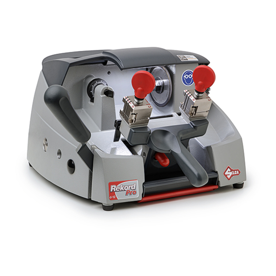
- Page 1 REKORD d-12 Operating Manual Translation of original instructions D4A5532XA vers. 3.0...
- Page 2 © 2022 SILCA S.p.A - Vittorio Veneto This manual has been drawn up by SILCA S.p.A. All rights reserved. No part of this publication can be reproduced or circulated by any means whatsoever (photocopies, microfilm or other) without the consent of SILCA S.p.A.
-
Page 3: Table Of Contents
INDEX USE OF THE MANUAL .............................1 GENERAL WARNINGS .............................3 MAIN WORKING PARTS ..........................4 MACHINE DESCRIPTION ..........................5 2.1 Further Risks ..............................6 2.2 Technical Data ..............................6 2.3 Electric circuit ..............................7 2.4 Accessories provided ............................8 TRANSPORT ..............................9 3.1 Packing ................................9 3.2 Unpacking ............................... -
Page 5: Use Of The Manual
This manual must be read and its contents acquired by those who will use it. Manufacturer’s ID REKORD PRO d-12 has an ID plate located on the back of the machine, showing the serial number. Fig. 1 (*) see Ch. 8 DISPOSAL. - Page 6 6) Back GRAPHICS IN THE MANUAL Obligation to read Obligatory use Pay attention the manual of otoprotectors GRAPHICS ON THE REKORD PRO d-12 KEY-CUTTING MACHINE Obligatory use Do not clean with Obligation to read Cutter motor of safety goggles compressed air...
-
Page 7: General Warnings
To guarantee maintaining these results over time, please follow the instructions below: • Observe the procedures described in this manual; • Always use Original Silca Tools as they are designed to make the best of REKORD PRO d-12 and provide quality key-cutting;... -
Page 8: Main Working Parts
REKORD PRO d-12 Operating manual 1 MAIN WORKING PARTS Fig. 3 - carriage lever handle - carriage release lever - chippings tray - tool tray - carriage movement lever - clamps - clamp knobs - gauge knob - gauge tabs... -
Page 9: Machine Description
“read” from the originals. The working parts are described below: Cutting Tool The cutting tool (L) is the part of the REKORD PRO d-12 used for cutting key blanks. The cutting tool is in HSS super rapid steel. -
Page 10: Further Risks
REKORD PRO d-12 Operating manual Clamp knobs The clamps are locked by two anatomical knobs (F), which ensure perfect grip on the keys with only slight locking pressure. Gauges Next to the clamps there is a rod with two gauge tabs (H) to control key alignment. -
Page 11: Electric Circuit
1350 rpm, consumes approximately 0.18 Kw, absorption 2A (230V-50Hz) 1620 rpm, consumes approximately 0.18 Kw, absorption 2A (230V-60Hz) The main parts of the electric circuit on the REKORD PRO d-12 are listed below: 1) Main plug with fuses 2) Safety main switch 3) Push button 4) Motor: 230V a.c. -
Page 12: Accessories Provided
REKORD PRO d-12 Operating manual 2.4 Accessories provided REKORD PRO d-12 comes with a set of accessories for its operation and maintenance (tools, hex wrenches, fuses) supplied in a special tool kit comprising. Fig. 8 adjusting keys (2 pcs) allen key 5 mm steel bars (2 pcs) 1.5 mm/5 mm Allen key set... -
Page 13: Transport
The packed machine can be carried by one person. 3.1 Packing The REKORD PRO d-12 is packed in a strong cardboard box, the dimensions of which are shown in Fig. 9 sufficiently robust to be used for storing the machine for long periods. -
Page 14: Machine Installation And Preparation
However, it is always advisable to check that the machine has not suffered any damage. 4.2 Environmental conditions To ensure that the best use is made of the REKORD PRO d-12 key-cutting machine, certain parameters must be borne in mind: damp, badly ventilated sites should be avoided. -
Page 15: Separate Parts
REKORD PRO d-12 Operating manual 4.4 Separate parts The separately packed parts must be installed on the REKORD PRO d-12 key-cutting machine by the purchaser, as follows: 4.4.1 Carriage lever handle Screw the handle onto the carriage (Fig. 11). Fig. 11 4.4.2 Power cable... -
Page 16: Description Of Work Station
REKORD PRO d-12 Operating manual 4.6 Description of work station The key-cutting machine needs only one operator, who has the following controls at his/her disposal (Fig. 13): • main switch (O), located on the right-hand side of the machine; when activated the lamp (I) turns on. -
Page 17: Machine Regulation And Utilization
Axis calibration: Axis calibration is regulation of the space between cutting and the stop (Fig. 14 and Fig. 15). The axis setting for the REKORD PRO d-12 is fixed and is established on assembly in our workshops. Fig. 14 Fig. 15... - Page 18 REKORD PRO d-12 Operating manual Depth calibration: Depth calibration is regulation of the cutting depth (Fig. 14). Proceed as follows: 1) Ensure that the key-cutting machine is off by unplugging the power cable. 2) Place the adjustment keys (provided) on the clamps (Fig. 16).
- Page 19 REKORD PRO d-12 Operating manual Fig. 18 • Turn the nut to the RIGHT (clockwise) to take the tracer point down. Result: SHALLOWER CUTS. Fig. 19 • Turn the nut to the LEFT (anticlockwise) to take the tracer point up. Result: DEEPER CUTS.
-
Page 20: Cutting Operations
REKORD PRO d-12 Operating manual 6 CUTTING OPERATIONS ATTENTION: for complete safety during the cutting operations, take the following precautions: • Always work with dry hands. • Check that the machine is properly earthed. • Wear protective goggles even if the machine has a protective shield over the cutting tool. -
Page 21: Clamp Rotation
REKORD PRO d-12 Operating manual Fig. 21 D-12 CLIQ Fig. 22 Fig. 23 6.1.1 Clamp rotation Positioning the correct side to be used is quick and easy. 1) Loosen the clamp closing knob by a few turns. 2) Turn the clamp so that the required side is facing the tracer point and cutter. -
Page 22: Securing The Keys In The Clamps
ATTENTION: make sure the gauges (H) have been lowered. Once activated with the switch (O) the REKORD PRO d-12 machine is ready for the cutting operation: 1) Unlock the carriage with the lever (B) to activate the motor and move the carriage towards tracer/cutting tool. -
Page 23: Using The Accessories
The bars provided are used for cutting cruciform keys (Fig. 28) and as a tip rest for locking keys with no stop (Fig. 29). Cutting cruciform keys using bars The cruciform keys (90°) can be cut with the REKORD PRO d-12 clamps and the aid of the bars. Positioning cruciform keys: 1) Leave the gauges (H) in the idle position. - Page 24 REKORD PRO d-12 Operating manual Fig. 28 Tip stop with a bar The bars can be used with keys which have no stop. Proceed as follows: 1) Leave the gauges (H) in the idle position. 2) Insert the bars into the slot in the clamps.
-
Page 25: Maintenance
REKORD PRO d-12 Operating manual 7 MAINTENANCE ATTENTION: for repairs or replacement of parts for maintenance, the ‘CE’ mark is guaranteed only if original spare parts provided by the manufacturer are used. Although the key-cutting machine does not require special maintenance, it is advisable to check and, if necessary, replace the parts subject to wear, such as: the belt, cutting tool, brush, tracer point. -
Page 26: Replacing The Cutting Tool
REKORD PRO d-12 Operating manual 7.2 Replacing the cutting tool To replace a worn cutting tool, proceed as follows: ATTENTION: remove the mains plug. 1) Slot the locking rod (provided) into the hole of the cutting tool shaft (Fig. 32). -
Page 27: Replacing The Tracer Point
REKORD PRO d-12 Operating manual 7.3 Replacing the tracer point ATTENTION: remove the mains plug. 1) Remove the two pads (Fig. 34). 2) Loosen the 3 screws (M1) and remove the top cover (M) (Fig. 34 and Fig. 35). 3) Loosen the screw (K1) (Fig. 36). -
Page 28: Access To The Lower Compartment
REKORD PRO d-12 Operating manual 7.4 Access to the lower compartment ATTENTION: remove the mains plug. 1) Detach the wire from the key-cutting machine socket. 2) Remove the double box (tool holder/swarf tray) (Fig. 38). 3) Turn the machine over onto its back. -
Page 29: Replacing Lamp Feed (Transformer)
REKORD PRO d-12 Operating manual 7.5 Replacing lamp feed (transformer) ATTENTION: remove the mains plug. 1) Access the lower compartment (chap.7.4). 2) Loosen the 2 low voltage connector screws (Q1) remove and place in their seat on the new trans-former, securing with the 2 screws (Fig. -
Page 30: Replacing Lamp Set/Lamp Protection
REKORD PRO d-12 Operating manual 7.6 Replacing lamp set/lamp protection • Lamp set ATTENTION: remove the mains plug. 1) Remove the two pads (Fig. 43)). 2) Loosen the 3 screws (M1) and remove the top cover (M) (Fig. 34). 3) Access the lower compartment (chap.7.4). -
Page 31: Replacing The Fuses
Fig. 45 7.8 Regulating carriage depth The carriage on the REKORD PRO d-12 can be regulated to protect the clamps from coming into contact with the tracer point or cutting tool. IMPORTANT: the play between cutting tool/tracer point and clamps must be 0.1 mm. -
Page 32: Replacing The Main Switch
REKORD PRO d-12 Operating manual 7.9 Replacing the main switch ATTENTION: remove the mains plug. 1) Access the lower compartment (chap.7.4). 2) Detach the 4 connectors (Y1) paying special attention to their position (Fig. 47). 3) Remove the switch (O) making pressure on the tabs with a screwdriver (Fig. 48). -
Page 33: Sostituzione E/O Tensionamento Della Cinghia
REKORD PRO d-12 Operating manual 7.11 Sostituzione e/o tensionamento della cinghia Worn or loose belts (T) must be replaced or adjusted so as to ensure safe and proper operation of the cutting tool/ brush. • Tension: ATTENTION: remove the mains plug. - Page 34 REKORD PRO d-12 Operating manual Fig. 53 Fig. 54 Fig. 55 Fig. 56 Copyright Silca S.p.A 2022...
-
Page 35: Replacing Motor/Condenser
REKORD PRO d-12 Operating manual 7.12 Replacing motor/condenser ATTENTION: remove the mains plug. 7.12.1 Replacing motor 1) Remove the two pads (Fig. 51). 2) Loosen the 3 screws (M1) and remove the top cover (M) (Fig. 52). 3) Access the lower compartment (chap.7.4) 4) Detach the connectors (S2) from the brush push-button (Fig. - Page 36 REKORD PRO d-12 Operating manual Fig. 59 Fig. 60 10) Return the machine to its upright position. 11) Install the belt and tighten the 4 screws (S1) (Fig. 55) of the plate motor. 12) Push the belt tightener (P1) downwards to tighten the belt and secure it with the screw (P2).
-
Page 37: Replacing The Microswitch
REKORD PRO d-12 Operating manual 7.13 Replacing the microswitch ATTENTION: remove the mains plug. 1) Access the bottom compartment (ch.7.4). 2) Disconnect the connectors (Z1) from the microswitch. 3) Loosen the fixing nut and remove the micro-switch. 4) Install the new microswitch and regulate by means of the fixing nut;... -
Page 38: Disposal
REKORD PRO d-12 Operating manual 8 DISPOSAL For correct disposal please refer to current standards. INFORMATION FOR USERS OF PROFESSIONAL EQUIPMENT From “Actuation of Directive 2012/19/EU regarding Waste Electrical and Electronic Equipment (WEEE)” The symbol of a crossed waste bin found on equipment or its packing indicates that at the end of the product’s useful life it must be collected separately from other waste so that it can be properly treated and recycled. -
Page 39: Assistance
9.1 How to request service The guarantee attached to the key-cutting machines ensures free repairs or replacements of faulty parts within 24 months of purchase. All other service calls must be arranged by the customer with Silca or with a Silca service centre. - Page 40 EN 62233:2008 EN 62471:2008 EN IEC 55014-1:2021; EN IEC 55014-2:2021; EN 55035:2017 + A11:2020 EN IEC 61000-3-2:2019 + A1:2021 EN 61000-3-3:2013 + A1:2019 + A2:2021 + A2/AC:2022 Silca S.p.A. R&D Division is authorized to create a Technical File. VITTORIO VENETO, 15/06/2022...
- Page 41 BS EN IEC 55014-1:2021; EN IEC 55014-2:2021; EN 55035:2017 + A11:2020 BS EN IEC 61000-3-2:2019 + A1:2021 BS EN 61000-3-3:2013 + A1:2019 + A2:2021 + A2/AC:2022 Silca S.p.A. R&D Division is authorized to create a Technical File. VITTORIO VENETO, 15/06/2022...
Need help?
Do you have a question about the REKORD PRO d-12 and is the answer not in the manual?
Questions and answers