Table of Contents
Advertisement
Quick Links
Advertisement
Table of Contents

Related Manuals for Silca Crown D422143XA


Summary of Contents for Silca Crown D422143XA
- Page 1 CROWN CROWN Operating manual D422143XA vers. ®...
- Page 2 This manual has been drawn up by SILCA S.p.A. All rights reserved. No part of this publication may be reproduced or used in any form or by any means (photocopying, microfilm or other) without the written permission of SILCA S.p.A. published in october 2001 Printed in Vittorio Veneto by SILCA S.p.A.
-
Page 3: Table Of Contents
INDEX TRANSPORT ......................3 Packing ......................3 Transport ......................3 Unpacking ......................3 Machine handling .....................3 WORKING PARTS .....................4 MACHINE DESCRIPTION ..................5 Technical data ....................6 Electrical circuit ....................6 ACCESSORIES PROVIDED ..................7 MACHINE INSTALLATION AND PREPARATION ............8 Checking for damage ..................8 Environmental conditions .................8 Positioning .......................8 Description of work station ................9 Separate parts ....................9 Connection to the mains ..................9... - Page 5 The contents of the manual are divided into sections relating to: Chapter Transport and handling ........................1 Description of machine and safety devices ................2-3-4-5 Proper use of the machine ......................5-6 Maintenance ..........................7 Optional devices ........................... 10 Copyright Silca 2001...
- Page 6 If the machine is used differently or for purposes different from those described in this manual, the customer will forego any rights he may have over SILCA S.p.A. Furthermore, unforeseen danger to the operator or any third parties may arise from incorrect use of the machine.
-
Page 7: Transport
When the CROWN key-cutting machine has been unpacked, place it directly on its workbench. This operation can be carried out by one person, firmly holding the base, and no other part, to lift and carry the machine. Copyright Silca 2001... -
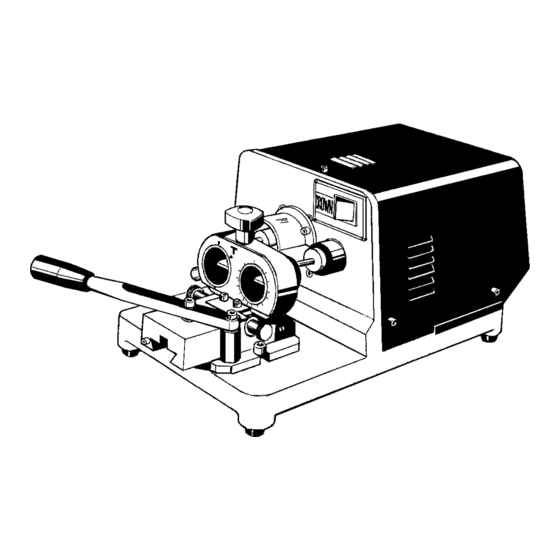
Page 8: Working Parts
D - Safety screen E - Slide F - Lever G - Height adjusting screw G1- Wedge locking knob H - Wedge L - Synchronised device (optional) Q - Safety device R - START button S - STOP button Copyright Silca 2001... -
Page 9: Machine Description
The device installed, in this case a T10, is used to seat the key to be copied on the right and the key blank to be cut on the left. Devices may vary according to the type of key to be cut. Their names, installation and operation are described in this manual (see cap.10 a pag.15). Copyright Silca 2001... -
Page 10: Technical Data
3) Relay 3 contacts 220V 4) STOP button 5) Relay contacts 6) Safety device plug 7) Machine plug 8) Fuse rapid 5x20 3,15A - 250V 9) Master switch 10) Motor 230Va.c. 50Hz 11) Condenser 6,3 µF safety device Copyright Silca 2001... -
Page 11: Accessories Provided
D300219ZZ 2,5 mm ALLEN KEY 3 mm ALLEN KEY cod. D300223ZZ cod. D302883ZZ 3 mm ALLEN KEY 8 mm SPANNER cod. D300224ZZ cod. D309226ZZ 4 mm ALLEN KEY FUSE 5X20 (2 pz) 3,15 Amp fuse-rapid (230V) Copyright Silca 2001... -
Page 12: Machine Installation And Preparation
Check that the weight of the machine is evenly distributed over the four feet; horizontal positioning prevents vibrations during operation. WARNING: ensure that the machine voltage is the same as that of the mains, which must be properly earthed and provided with a differential switch. Fig. 4 Copyright Silca 2001... -
Page 13: Description Of Work Station
Connection to the mains It is extremely important for the operator’s safety to ensure that the key-cutting machine is connected to the power mains with the right voltage and by means of a properly earthed differential switch. Copyright Silca 2001... -
Page 14: Regulation And Use Of The Machine
The height of the wedge is adjusted solely by means of the self-centring devices, the instructions for the use of which are included in this manual (see ch.10, page 15.). Using the standard synchronised devices the position of the wedge should be on 0. Fig. 7 Copyright Silca 2001... -
Page 15: Cutting Operations
Use the protective goggles, even if the cutting tool is fitted with a protective shield. • Start the motor only when all the operations with the carriage have been carried out (securing keys, etc.). • Keep hands away from the cutting tool when in motion. Copyright Silca 2001... -
Page 16: Maintenance
3) remove the fuse box placed below the power inlet (fig. 9); 4) replace the fuses; 5) close the fuse box and connect the power cable. WARNING: the fuses must both be of the same type (rapid) and with the same amps (3,15A) fuses fuse box Fig. 9 Copyright Silca 2001... -
Page 17: Waste Disposal
12 01 01 - Paper and cardboard packaging 15 01 01 - Plastic packaging 15 01 02 (**) "Waste" is any substance or object deriving from human activity or natural cycles, thrown away or to be thrown away . Copyright Silca 2001... -
Page 18: Assistance
How to request service The guarantee attached to CROWN key-cutting machine ensures free repairs or replacements of faulty parts within 12 months of purchase. All other service calls must be arranged by the customer with Silca or with a Silca Service Centre... -
Page 19: Synchronised Devices
VIGIE-PICARD CAVITH D700192ZB D704534ZB for: for: LAPERCHE VIGIE-PICARD D700193ZB D709355ZB for: for: D700194ZB for: DAD-DECAYEUX D700329ZB D705355ZB for: for: tubolar keys tubular keys ø universal ø universal mm 9,2 ... mm10,2 mm 6 ... mm12,5 Copyright Silca 2001... -
Page 20: Devices T2 - T3 - T4 - T5 - T6 - T7 - T8 - T9 - T13
5) Take the carriage back to the idle position, release rotation by means of the knob (K) and turn the key clockwise until it reaches the next notch, block the knob (K) and make the second cut. 6) Repeat the operation above until all the cuts have been made. Fig. 10 Fig. 11 Copyright Silca 2001... -
Page 21: Self-Centering Device T10
3) Fit in and lock the sample key and the keyblank as described above in points 3 and 4. 4) Rotate the ring nut (W) counter clockwise until the tracer point is in front of the first cut, lock the han- dle (K1) and carry out the duplication repeating these operations for each cut. Copyright Silca 2001... - Page 22 This small difference will cause no problems in operation and will help to avoid errors in centering. correspondence cut with step pin with (cut within a cut) step CYLINDER correspondence normal normal oversized oversized Fig. 14 Copyright Silca 2001...
- Page 23 CENTURY 10,02 7,52 8,36 0,75 CHICAGO 10,16 8,30 8,65 0,95 CHICAGO 9,30 7,60 7,75 0,82 FORT MAS. 9,53 7,20 7,62 1,15 MERONI 9,55 8,05 8,36 0,75 PC (CORTELLEZZI) 9,65 8,00 8,32 0,83 SIDLEEN 9,50 7,50 8,20 1,00 Copyright Silca 2001...
-
Page 24: Self-Centering Device T15
8,2 mm (with a thickness of 1 mm). T 15 cutter Hold the T15 well up against its rest locking with (M) section Fig. 16 Copyright Silca 2001... - Page 25 9,80 1,10 6 - 5,4 “ 6,50 5,2 - 7,2 1,30 6 - 5,4 “ 7,2 - 9,2 1,50 6 - 5,4 “ 5,50 0,75 6 - 5,4 OLIVETTI 5,40 5,70 0,80 3 - 2,4 1+2+1 -0,3 Copyright Silca 2001...
-
Page 26: T14 Synchronised Device For Cutting 5Vp3 Keys
Secure in position with the knob (K1) and cut. 8) Cutting positions 3 - 7 Move the shim (E1) completely to the left and repeat the same operations described above at point 7. 0,6 mm left right Fig. 18 Copyright Silca 2001... -
Page 27: T17 Synchronised Device
5) release the knob (K1) (fig. 22) and push on the head of the key to be cut to turn it clockwise until it clicks into place for the next cut. Continue in this way for all the cuts. Fig. 20 Copyright Silca 2001... - Page 28 Operating manual - English CROWN Fig. 21 Fig. 22 Copyright Silca 2001...
- Page 29 SILCA S.p.A. Via Podgora, 20 (Z.I.) 31029 VITTORIO VENETO (TV) Tel. 0438 9136 Fax 0438 913800 www.silca.it Member of the Kaba Group...
Need help?
Do you have a question about the Crown D422143XA and is the answer not in the manual?
Questions and answers